LabVIEW与西门子PLC通信实现工业自动化系统的控制与监测

labview和西门子plc通信
知识点和领域范围:LabVIEW、西门子PLC、通信

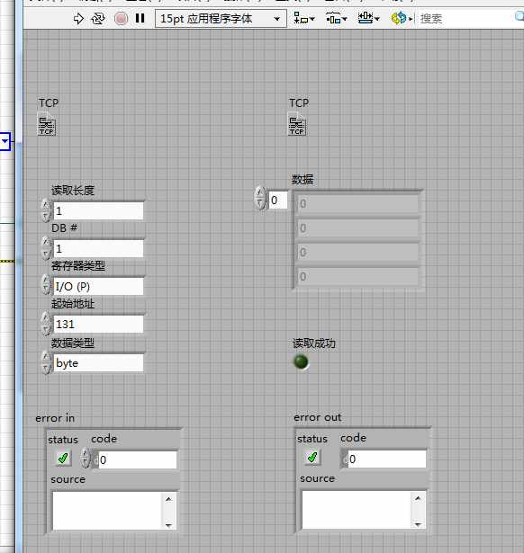
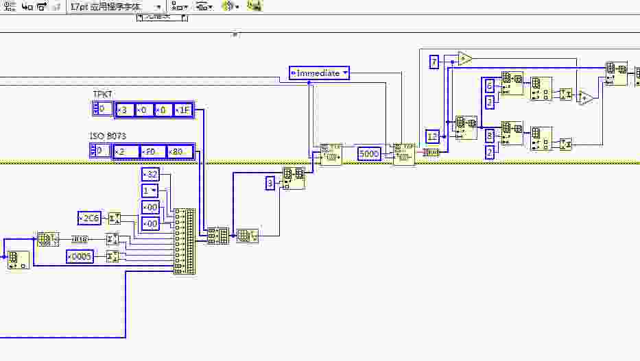
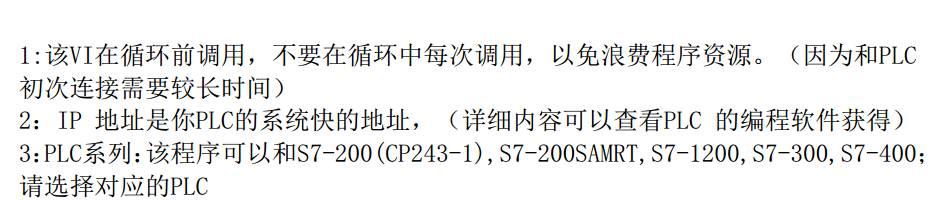
LabVIEW是一种图形化编程环境,用于控制和测量系统的设计和开发。它提供了一个直观的界面,使工程师能够通过拖放和连接图标来创建程序。西门子PLC(可编程逻辑控制器)是一种常用的工业自动化设备,用于控制和监控生产过程。通信是指不同设备之间的数据交换和信息传递。

延申科普:
LabVIEW是一种流行的编程语言和开发环境,广泛应用于自动化、测量和控制系统。它的图形化编程方式使得非专业编程人员也能够快速开发复杂的控制系统。LabVIEW可以与各种设备进行通信,包括传感器、执行器和其他计算机系统。

西门子PLC是一种常见的工业自动化设备,用于控制和监控生产过程。它能够接收输入信号,执行特定的逻辑操作,并输出控制信号来实现自动化控制。与LabVIEW结合使用,可以实现对PLC的编程和监控。

通信在工业自动化中起着重要的作用。不同设备之间的通信可以实现数据的交换和信息的传递,从而实现系统的协调和控制。常见的通信方式包括以太网、串口通信和现场总线等。通过通信,LabVIEW可以与PLC进行数据交互,实现对PLC的控制和监测。

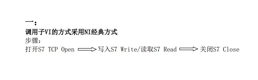
总结:LabVIEW和西门子PLC通信是指利用LabVIEW作为编程环境,通过通信方式与西门子PLC进行数据交互和控制。这种通信方式在工业自动化领域中广泛应用,可以实现复杂系统的控制和监测。

ID:61100583859613305

测控助手


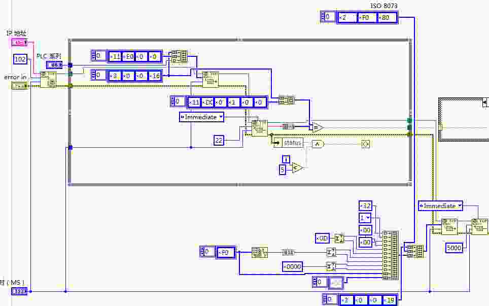
LabVIEW和西门子PLC通信在工业自动化领域中扮演着重要的角色。LabVIEW作为一种直观的图形化编程环境,为工程师提供了一个简化的开发界面,使他们能够通过拖放和连接图标的方式来创建程序。而西门子PLC作为常用的自动化设备,负责控制和监控生产过程。通过LabVIEW与西门子PLC之间的通信,能够实现数据交互和系统的协调控制。

首先,LabVIEW是一种流行的编程语言和开发环境,广泛应用于自动化、测量和控制系统。它的图形化编程方式使得非专业编程人员也能够快速开发复杂的控制系统。LabVIEW可以与各种设备进行通信,包括传感器、执行器和其他计算机系统。通过与西门子PLC的通信,LabVIEW能够实现对PLC的编程和监控,从而实现对生产过程的控制和调节。

西门子PLC作为一种常见的工业自动化设备,被广泛应用于工业领域。它能够接收输入信号,执行特定的逻辑操作,并输出控制信号来实现自动化控制。与LabVIEW结合使用,可以实现对PLC的编程和监测。通过LabVIEW和西门子PLC之间的通信,工程师可以轻松地对PLC进行编程,实现对生产过程的控制。

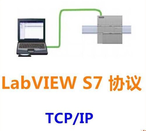
通信在工业自动化中起着重要的作用。通过通信,不同设备之间可以实现数据的交换和信息的传递,从而实现系统的协调和控制。常见的通信方式包括以太网、串口通信和现场总线等。在LabVIEW和西门子PLC的通信中,通常会采用以太网通信的方式进行数据交互。通过以太网通信,LabVIEW可以实时收集PLC的状态信息,控制PLC的运行,并将数据传输回LabVIEW以进行进一步的处理和分析。

LabVIEW和西门子PLC通信的应用场景广泛。以工业生产过程为例,通过LabVIEW与西门子PLC的通信,工程师可以实时监测生产设备的状态信息,控制设备的运行模式,实现自动化生产和远程控制。此外,LabVIEW和西门子PLC的通信也可以应用于物联网、智能家居等领域,实现设备之间的互联互通和智能化控制。

综上所述,LabVIEW和西门子PLC通信是一种重要的技术应用,它利用LabVIEW作为编程环境,通过以太网通信等方式与西门子PLC进行数据交互和控制。这种通信方式在工业自动化领域中广泛应用,能够实现复杂系统的控制和监测。通过LabVIEW和西门子PLC通信的应用,工程师能够快速开发控制系统,实现自动化控制和智能化管理。

以上相关代码,程序地址:http://matup.cn/583859613305.html

  • 19
    点赞
  • 10
    收藏
    觉得还不错? 一键收藏
  • 2
    评论
西门子PLC通讯的Labview库,还不错。 以下是英文声明: Warning, the attached files are experimental VIs provided for educational purposes only. No warrantee is expressed or implied. You should test your code and completely understand the implications of writing to or reading from an operating PLC. PLCs are often used to control hazardous processes and/or equipment. Writing to or reading from a PLC in active control of equipment or process can result in the disruption of the PLC program or data areas, potentially causing economic loss, property damage, generation or release of hazardous substances and/or personal injury up to and including death. Test your software in a controlled environment and qualify it before using it on active equipment or processes. To my knowledge, Siemens has never released the details of the S7 protocol. Much of what is publicly available on S7 is based on observations of the protocol by others. There is an open source S7 data exchange package available at http://libnodave.sourceforge.net/ that documents many S7 features. These VIs were based upon the example posted at http://decibel.ni.com/content/docs/DOC-5467. They were modified by observing and mimicking a S7 data exchange between a protocol converter and a S7-300 series PLC. The observations were accomplished with the wireshark network protocol analyzer, available at http://www.wireshark.org/ and the Wireshark Plugin f黵 S7-Protokoll, available at http://sps-forum.de/showthread.php?p=202763. The Address Area parameter determines which PLC memory area is the target for the reads and writes. I have only tested reads and writes to the Data Block (DB) Area. Your application should read and write to separate read and write DBs dedicated for transfer only. By confining reads and writes to dedicated Data Blocks, the risk of unintended overwrites may be reduced. The data type: S7Com_Transport_Size.ctl is a ring variable that contains the parameter for the size or type of the transfer. I have only had success with the BYTE, INT and DINT transport sizes on an S7-300 series PLC. The other sizes remain in the ring variable for testing on other PLCs. I do not know if the bytes of a multiple-byte variable are read or written atomically. The example contains two top-level VIs: S7Com_Once.vi and S7Com_W+R_Loop.vi. S7Com_Once.vi performs one read or write per execution. It writes to the target PLC from an array of I32, it reads from the target PLC into an array of I32. The number of bytes written is proportional to the number of elements in the array to be written and the transport size parameter. S7Com_W+R_Loop.vi regularly writes to and reads from a pair of DBs in the target PLC. In order to use it, your Step7 PLC project should provide two Data Blocks, DB11 and DB12. See the screen capture image db11&12.PNG for their layout. After downloading the DBs to your PLC, monitor and change DB VAlues with a VAT. As can be seen in the VI, the transfer size is DWORD. Included are example VIs (S7Com_to_PLC(SubVI).vi and S7Com_from_PLC(SubVI).vi) to map variables between Labview and the S7 PLC DBs. In the example, they use the same cluster type definition (S7Com_PLC_Data.ctl) but that is not a requirement. When you change the mappings, you must calculate the size of the variables to be read from the PLC in order to use the correct Read Length parameter. The read length parameter is in transport size units. The write length parameter is taken from the size of the write data array, so if the write data array is larger than you anticipate, data may be overwritten. The hex byte and hex byte array type definitions were created to format the internal data structures to show hex values so that they could be easily compared to the wireshark packet dumps. These VIs have been minimally tested on a NI 9072 cRIO. This is not finished. Needed are better error checking, cleaner S7 Response decoding, and stress testing with malformed data.

“相关推荐”对你有帮助么?

  • 非常没帮助
  • 没帮助
  • 一般
  • 有帮助
  • 非常有帮助
提交
评论 2
添加红包

请填写红包祝福语或标题

红包个数最小为10个

红包金额最低5元

当前余额3.43前往充值 >
需支付:10.00
成就一亿技术人!
领取后你会自动成为博主和红包主的粉丝 规则
hope_wisdom
发出的红包
实付
使用余额支付
点击重新获取
扫码支付
钱包余额 0

抵扣说明:

1.余额是钱包充值的虚拟货币,按照1:1的比例进行支付金额的抵扣。
2.余额无法直接购买下载,可以购买VIP、付费专栏及课程。

余额充值