


Yes, that’s right, we have another new BGP NLRI: BGP-LS. In this post we will be looking at BGP with Link State (LS) extension which is an integral part of the Carrier SDN strategy. We will look at why we need BGP-LS, its internals and its applications. What I won’t cover is things like do we need SDN?, whether all network engineers have to become programmers? Or any other bigger questions threatening humanity.
Problem Space:
Centralized LSP Path Computation
So as you may already know that with traditional RSVP-TE, there are certain problems with distributed computation like bin-packing or optimal path computation for Multi-area/Multi-AS TE. The crux of the issue here is that a Head End router has a limited visibility in his domain (a single AS or Single IGP area), whether it’s the number of LSPs in-flight (related to bin packing) or LSDB for other areas (AS or IGP Area). These problems are hard to solve with distributed computation and it makes sense to move LSP path computation for these kind of problems to a central controller which has visibility to the entire domain or more than one domain which allows it to calculate the paths efficiently, which then can be signaled by the controller to the head-end node about the path which is end to end optimal.
One example of a central controller is PCE [RFC4655] which can be used to compute MPLS-TE paths within a domain or across multiple domains (multi-area or multiple ASes). In previous proposed solutions for multi-domain path computation source routers uses a technique called “loose-hop-expansion”, and selects the exit ABR and other ABRs using IGP shortest path topology. This approach has various disadvantages like calculating sub-optimal paths, makes alternate/backup path computation hard and may result in no TE path behind found when one exists [I will cover this topic in detail in my future blogposts on PCE/PCEP].
Even in the world of Segment Routing, Traffic steering problem will be solved by a centralized path controller by calculating the paths at the controller and then signaling it to the head end node.
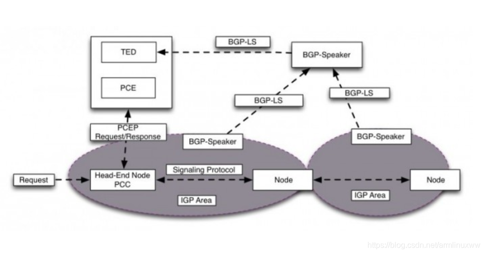
But in order for a central controller like PCE to calculate end-to-end optimal paths, it needs a database which has topology info on which it runs its path computation. The database is usually known as Traffic Engineering Database (TED) and in order to build that database, a controller needs details about the topology and resource information of the domain like link bandwidth, available bandwidth, link metric, the TE metric etc.
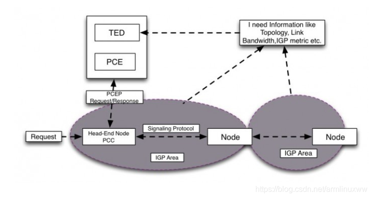
Fig.1
One way we can solve this problem, i.e. Getting topology and resource info is by making Controller peer passively with an IGP node to get all the link state information. This is how people have solved the problem of getting IGP info in the past, but the problem with this approach is that
- A practical controller code needs to support both OSPF and IS-IS.
- IGP tends to be very chatty, so the controller will spend some time processing all the chatty updates.
- In the cases where the network consists of multiple IGP domains across geographic areas then it could be a challenging on where to place the central entities i.e. A controller which peers with IGP.
Or an alternative approach could be to extend BGP by creating another NLRI which can carry all the IGP info over BGP. In this approach we can leverage an in-network, BGP speaker that is already participating in the IGP, BGP Speaker can retrieve info from IGP LSDBs and distribute it to a controller, either directly or via a peer BGP speaker. The BGP speaker can apply any filters before sending the info northbound to the controller.
Advantages of this approach are:
- Controller implementation has to only support BGP.
- BGP tends to be less chatty compared to IGPs.
- In a network with multiple IGP domains, extending peering over BGP is a lot more feasible compared to IGP.
This is what BGP-LS is all about. Once you have the topology info, you can also write an application to draw the network topology graphs which can be updated dynamically as the topology changes occur like if a node or link went down. This may seem minor, but I think it’s pretty handy.
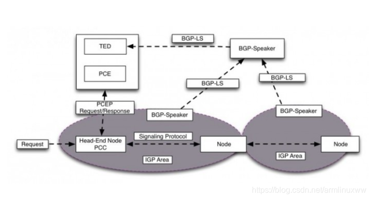
Fig.2
BGP-LS Internals
Now let’s look dig deep into BGP-LS internals. So as you know that an IGP consists of topology and IP reachability information and if we want to reconstruct an IGP Topology view at the controller based on the data received over BGP-LS then BGP-LS must have some way to represent Topology and IP reachability information in its database. So let’s take a look and see how this is done.
BGP-LS specification contains two parts:
- Definition of a new BGP NLRI type which is essentially sets of TLV’s that defines three objects:
- Nodes
- Links
- IP Prefixes
With the combination of Node and Link objects one can construct a topology info and IP Prefix object will provide IP reachability information.
- Definition of a new BGP path attributes (BGP-LS attribute) which is optional Non-transitive attribute. It encodes the properties of the objects (link, node and prefix). For instance, it could be Node-names, IGP metric, TE-metric, Available BW etc.
1. BGP-LS NLRI: Format of Link-state NLRI is shown below
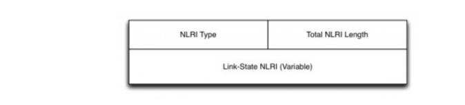
Fig.3
As we mentioned earlier, there are basically three types of NLRI: Node, Link and Prefix NLRI (Type 3 and 4).
Type 1 Node NLRI: Node NLRI is pretty self-explanatory. It contains Node descriptor and Node attributes. Typically, Node descriptor will be the Router-ID and is carried under the value field of the Local Node Descriptor.
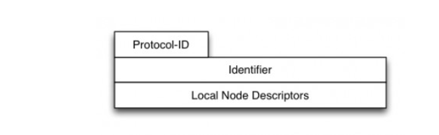
Fig.4
Type 2 Link NLRI: Link NLRI represents a link in the network. Where local and remote Nodes are the two endpoints and the Link descriptor is the link between local and remote nodes. The link description field is a set of TLVs uniquely identifying a unidirectional connection between a pair of adjacent nodes.
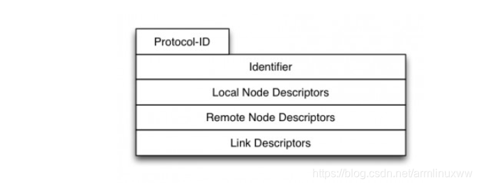
Fig.5
A link described by the Link descriptor TLVs actually is a “half-link”, a unidirectional representation of a logical link. In order to fully describe a single logical link, two originating routers advertise a half-link each, i.e. two link NLRIs are advertised for a given point-to-point link.
Type 3 and 4 Prefix NLRI: Type 3 and 4 uses the same format and contains Prefix descriptor and attributes. The ‘Prefix Descriptor’ field is a set of Type/Length/Value (TLV) triplets.‘Prefix Descriptor’ TLVs uniquely identifies an IPv4 or IPv6 Prefix originated by a Node.
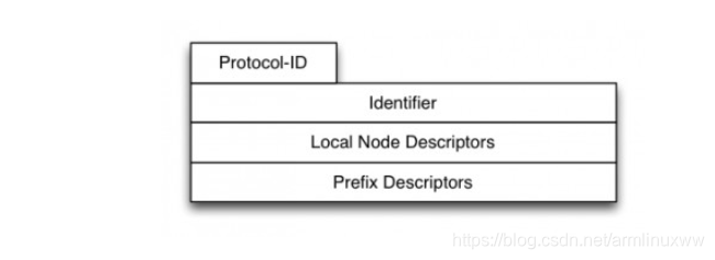
Fig.6
2.BGP-LS Path Attributes:
Path attributes are used to carry necessary attributes to characterize the objects described above i.e. Node, Link or Prefix NLRI. It’s again in TLV format and will include things like Node Name, Maximum Link Bandwidth, IGP Metric, Unreserved bandwidth, SRLG etc.
- Node Attribute: Node attributes TLVs may be included in the BGP-LS attribute accompanying a node NLRI. This may include things like Node Name, Router-ID, Multi-Topology identifier etc.
- Link Attributes: They are presented together with the corresponding link NLRI describing the link. Link attributes can be sourced from any of the extensions for the IGP routing protocols (IS-IS/OSPF). Link Attributes are like Metric, Max Bandwidth, unreserved Bandwidth, available Bandwidth etc.
BGP-LS Demo
At this point we have some idea of what consists of BGP-LS at a high level. Let’s look at a sample topology, which may bring more clarity. In my topology (Fig.7), I have four IOS-XR routers running the software version which has support for BGP-LS. Juniper supports BGP-LS as well, but at the time of writing, I didn’t have the access so I was stuck with using IOS-XR only in the topology. All the routers are running IS-IS Level-2 as IGP on the point-to-point links.
Router XRv1 is peering over BGP-LS with Open Daylight Controller (ODL). End goal here is that XRv1 will send all the IGP topology info over BGP-LS to the ODL. Once ODL has that information, we can use that information for LSP path computation or creating an application to visualize the topology. In this post, we will be looking at the sample app to draw the topology by grabbing the info from ODL over RestConf.
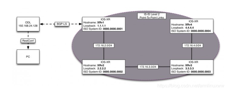
Fig. 7
BGP-LS Config on XRv1
Below is the highlighted relevant config under IS-IS and BGP to configure BGP-LS on Router XRv1 which is peering with ODL. Note that I am only redistributing IS-IS Level-2 information into BGP-LS.
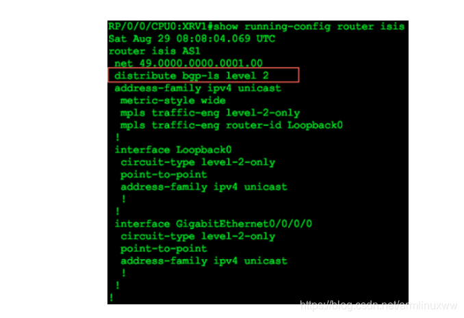
Fig.8
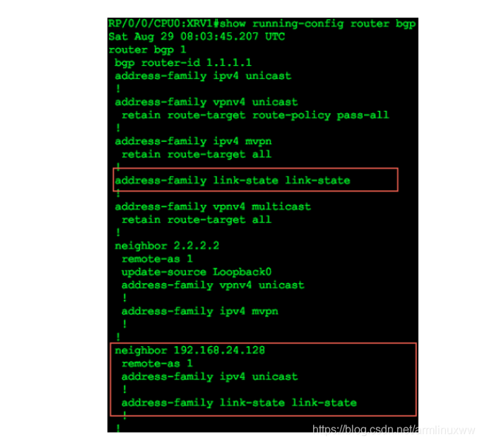
Fig.9
After configuring the above lines of config, BGP-LS neighbor relationship is up with ODL. Now let’s take a look on whether BGP-LS database has everything present to correctly derive our IGP topology.
If you look at the below fig.10 which is a logical representation of our topology of Fig.7, we can infer few things like
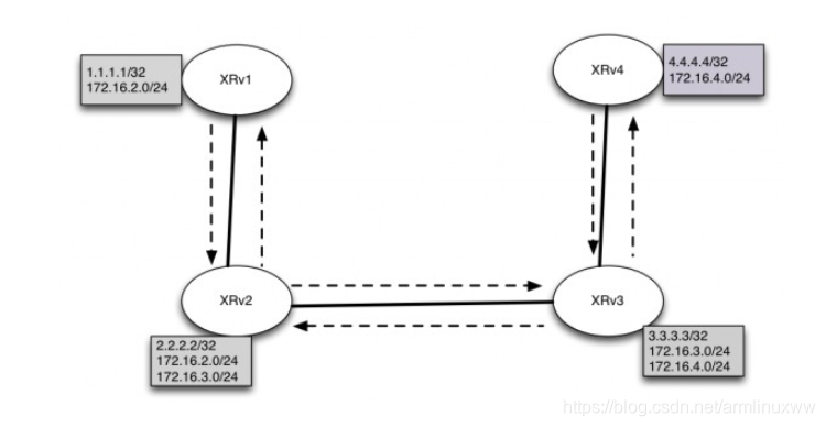
Fig.10
- Number of Nodes: We have 4 IGP Node’s. So I should expect 4 Node descriptors (Type 1) in BGP-LS database to correctly describe the number of nodes. [Needed for creating Topology]
- Number of Links: We have 3 Point-to-Point links so we should have 6 (3×2) Link descriptors (Type 2) to correctly describe all the links. If you recall each link descriptor represents a half-link that’s why we need to have 6 not 3 link descriptors. We should also have additional info about the links like the Bandwidth available, TE-metric, IGP metric etc. Encoded as BGP-LS Path attributes. [Needed for creating Topology]
- Number of Prefixes: There are total 10 Prefixes in our topology. So we should see 10 Prefix descriptor (Type 3 for IPv4) advertised by respective Node’s.[Needed for IP Prefix reachability]
Below is an output from BGP-LS database on XRv1:
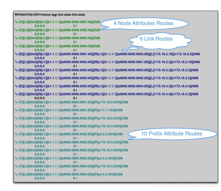
Fig.11 [V] denotes Node Descriptor, [E] denotes Link Descriptor and [T] denotes Prefix descriptor.
As you can see in the above Fig.11, we have exactly the same number of routes as we were expecting describing Node, link and IP Prefix information from which you can derive the IGP topology.
Let’s take a look at the following descriptors in detail to get some more clarity:
- Node Route descriptor for XRv1
- Two link descriptor(half-link) Routes for the link between XRv1 and XRv2
- Two IP Prefix routes for node XRv1(advertised by node XRv1)
So below is a detailed output of a Node descriptor for XRv1:
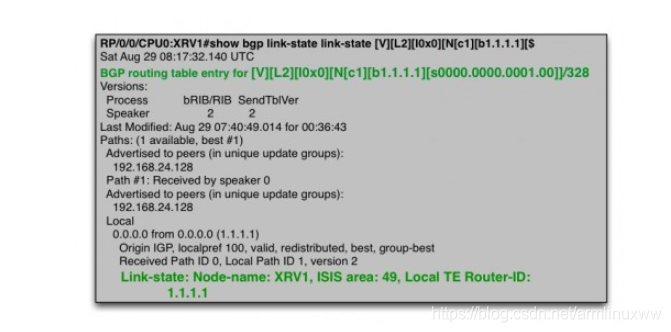
Fig.12
Let’s break the above route and see what information we can infer:
- [V]: Tells me that it’s a Node Route descriptor.
- [L2]: Tells me that it is a IS-IS Level 2 node.
- [s0000.0000.0001.00]]: tells me that the Node ISO-System id is 0000.0000.0001.00
- Node-Name: XRv1 Tells me that host-name is XRv1
- IS-IS Area: 49 Ideally It should be 49.0000. I still have to investigate why it only shows 49.But nevertheless you can combine IS-IS Area and ISO-Sytem-ID to derive that the area is 49.0000
- Router-ID is: 1.1.1.1
- And the obvious thing that we are running IS-IS as IGP
Similar information can be extracted from the other three Node Route descriptors.
Below is a detailed output of two Link descriptor routes for the link between XRv1 and XRv2.
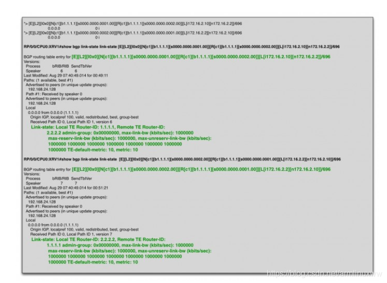
Fig.13
Let’s break the above link-route and see what information we can derive:
- [E]: This tells me it’s a Link Descriptor Route.
- [L2]: This tells me that IS-IS link type is L2 (adjacency type is only L2 as there are no other routes present with L1)
- [L[i172.16.2.10][n172.16.2.2]] : This part tells that the local Link is 172.16.2.10 and the neighbor link IP is 172.16.2.2
- [s0000.0000.0001.00]][R[c1][b1.1.1.1][s0000.0000.0002.00]] : This portion describes the half-link between ISO-Node 0000.0000.0001.00(local-Node) and 0000.0000.0002.00(remote Node).
- If you look at above two points and combine it with Node info, you can derive that it describes a half-link information between XRv1(0000.0000.0001.00) → XRv2((0000.0000.0002.00)) with Source Interface 172.16.2.10 and remote neighbor as 172.26.2.2
- Local TE Router-ID: 1.1.1.1, Remote TE Router-ID: 2.2.2.2 tells me that local and remote TE Router id is 1.1.1.1 and 2.2.2.2 respectively.
- TE-default-metric: 10, metric: 10: tells TE and IGP metric is 10 from XRv1 → XRv2
- It also has details like SRLG (Admin-Group) information and things like Available and Max Reserved BW.
In a similar way the bottom route gives the detail about the other half-link from XRv2 → XRv1. Combining both top and bottom half-links, one can derive that there is a bi-directional connectivity between XRv1 and XRv2 and its properties like IGP Metric, TE attributes etc.
Combing both Node and Link attributes one can infer Topology information. What’s missing is the reachability information which can be derived from the IP Reachability attribute.
Below is the IP reachability information for node XRv1 from Prefix descriptor routes :
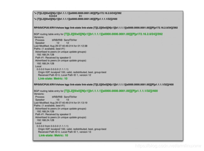
Fig.14
By looking at the above route we can derive following information.
- [T]: tells me that its a Prefix Descriptor Route.
- [P [p1.1.1.1/32]], [s0000.0000.0001.00] and “Link-state: Metric: 10” in the route tells me that Node with ISO-ID s0000.0000.0001.00 is advertising 1.1.1.1/32 with IGP metric 10
- [P[p172.16.2.0/24]] , [s0000.0000.0001.00] and “Link-state: Metric: 10” in the route tells me that Node with ISO-ID s0000.0000.0001.00 is advertising 172.16.2.0/24 with IGP metric 10
In a similar way you can derive the remaining prefixes advertised by other nodes from remaining IP Prefix descriptor routes. By this time, I am hoping this is all making sense to you.
BGP-LS Applications
Alright, so we looked so far that how the Topology and IP reachability details are exported from IS-IS to BGP-LS database. Since ODL is learning this info over BGP-LS, this information is available for our consumption. Now, as I mentioned earlier, at this point one can use this information for LSP path computation or write an application on top of ODL to draw the IGP topology. Some Vendors are already doing both, as that’s their value proposition on top of ODL and customers can do that as well if they have in-house development.
Just as a proof of concept, I wrote a quick script https://github.com/Dipsingh/BGP-LS-Topology-Grapher/blob/master/BGP-LS%20Topology%20Grapher to parse the BGP-LS info received over restconf from ODL and draw the IGP topology.
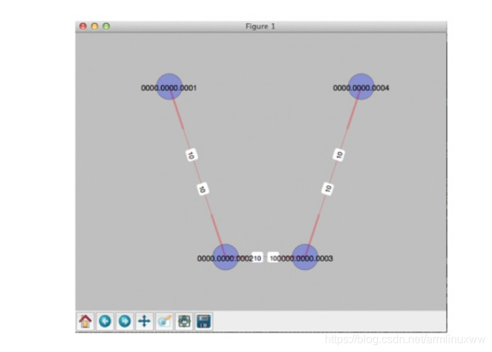
Fig.15
As you can see the graph has four nodes and the links with their IGP Cost. I am using ISO-System-ID as Node labels.
[ I know that the above graph looks ugly and probably so is my script :). Right now I am learning python and hoping to improve my skills over the years to write better code, so all the python experts looking at my code please bear with me for now]
Conclusion:
In this post we saw how BGP-LS can facilitate in gathering IGP topology of the network and exporting it to a central SDN Controller. I hope this post has been informative. In the future post we will look at PCEP and PCE in detail.
References:
https://tools.ietf.org/html/draft-ietf-idr-ls-distribution-11


 5309
5309

 被折叠的 条评论
为什么被折叠?
被折叠的 条评论
为什么被折叠?
 到【灌水乐园】发言


