


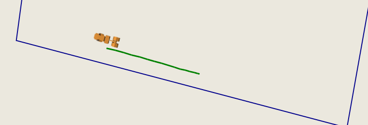
当小车图片最为marker时,显示在gmap地图上会和轨迹有些偏移,marker中心没有在轨迹点上
如图所示:
纠正偏移的代码如下(有些是我自定义的,根据自己的需求进行改正
GMarkerGoogle marker;
 Bitmap bitmap;
 PointLatLng newendLatLng;
//获得旋转之后的marker
 Bitmap bitmap = RotateImage(initialImage, pathAngle); //旋转图片的方法,pathAngle*(旋转角)在gps定位过程中了直接获取到
 //将gmap经纬度转换成控件坐标 endLatLng是下一个点的经纬度坐标
   gp = this.gMapControl.FromLatLngToLocal(new PointLatLng(endLatLng[0], endLatLng[1]));
 //将控件坐标转化成gmap经纬度
  newendLatLng = this.gMapControl.FromLocalToLatLng((int)gp.X, (int)(gp.Y + bitmap.Size.Height / 2));
 marker = new GMarkerGoogle(new PointLatLng(newendLatLng.Lat,newendLatLng.Lng), bitmap);
   traceMarkersOverlay.Markers.Add(marker);
将图片进行旋转的方法代码如下
        #region  旋转
        private static  Bitmap RotateImage(Image image,float angle)
        {

            if (image == null)
                throw new ArgumentNullException("image");

            const double pi2 = Math.PI / 2.0;

            // Why can't C# allow these to be const, or at least readonly
            // *sigh*  I'm starting to talk like Christian Graus :omg:
            double oldWidth = (double)image.Width;
            double oldHeight = (double)image.Height;

            // Convert degrees to radians
            double theta = ((double)angle) * Math.PI / 180.0;
            double locked_theta = theta;

            // Ensure theta is now [0, 2pi)
            while (locked_theta < 0.0)
                locked_theta += 2 * Math.PI;

            double newWidth, newHeight;
            int nWidth, nHeight; // The newWidth/newHeight expressed as ints

            #region Explaination of the calculations
            /*
			 * The trig involved in calculating the new width and height
			 * is fairly simple; the hard part was remembering that when
			 * PI/2 <= theta <= PI and 3PI/2 <= theta < 2PI the width and
			 * height are switched.
			 *
			 * When you rotate a rectangle, r, the bounding box surrounding r
			 * contains for right-triangles of empty space.  Each of the
			 * triangles hypotenuse's are a known length, either the width or
			 * the height of r.  Because we know the length of the hypotenuse
			 * and we have a known angle of rotation, we can use the trig
			 * function identities to find the length of the other two sides.
			 *
			 * sine = opposite/hypotenuse
			 * cosine = adjacent/hypotenuse
			 *
			 * solving for the unknown we get
			 *
			 * opposite = sine * hypotenuse
			 * adjacent = cosine * hypotenuse
			 *
			 * Another interesting point about these triangles is that there
			 * are only two different triangles. The proof for which is easy
			 * to see, but its been too long since I've written a proof that
			 * I can't explain it well enough to want to publish it.
			 *
			 * Just trust me when I say the triangles formed by the lengths
			 * width are always the same (for a given theta) and the same
			 * goes for the height of r.
			 *
			 * Rather than associate the opposite/adjacent sides with the
			 * width and height of the original bitmap, I'll associate them
			 * based on their position.
			 *
			 * adjacent/oppositeTop will refer to the triangles making up the
			 * upper right and lower left corners
			 *
			 * adjacent/oppositeBottom will refer to the triangles making up
			 * the upper left and lower right corners
			 *
			 * The names are based on the right side corners, because thats
			 * where I did my work on paper (the right side).
			 *
			 * Now if you draw this out, you will see that the width of the
			 * bounding box is calculated by adding together adjacentTop and
			 * oppositeBottom while the height is calculate by adding
			 * together adjacentBottom and oppositeTop.
			 */
            #endregion

            double adjacentTop, oppositeTop;
            double adjacentBottom, oppositeBottom;

            // We need to calculate the sides of the triangles based
            // on how much rotation is being done to the bitmap.
            //   Refer to the first paragraph in the explaination above for
            //   reasons why.
            if ((locked_theta >= 0.0 && locked_theta < pi2) ||
                (locked_theta >= Math.PI && locked_theta < (Math.PI + pi2)))
            {
                adjacentTop = Math.Abs(Math.Cos(locked_theta)) * oldWidth;
                oppositeTop = Math.Abs(Math.Sin(locked_theta)) * oldWidth;

                adjacentBottom = Math.Abs(Math.Cos(locked_theta)) * oldHeight;
                oppositeBottom = Math.Abs(Math.Sin(locked_theta)) * oldHeight;
            }
            else
            {
                adjacentTop = Math.Abs(Math.Sin(locked_theta)) * oldHeight;
                oppositeTop = Math.Abs(Math.Cos(locked_theta)) * oldHeight;

                adjacentBottom = Math.Abs(Math.Sin(locked_theta)) * oldWidth;
                oppositeBottom = Math.Abs(Math.Cos(locked_theta)) * oldWidth;
            }

            newWidth = adjacentTop + oppositeBottom;
            newHeight = adjacentBottom + oppositeTop;

            nWidth = (int)Math.Ceiling(newWidth);
            nHeight = (int)Math.Ceiling(newHeight);

            Bitmap rotatedBmp = new Bitmap(nWidth, nHeight);

            using (Graphics g = Graphics.FromImage(rotatedBmp))
            {
                // This array will be used to pass in the three points that
                // make up the rotated image
                Point[] points;

                /*
                 * The values of opposite/adjacentTop/Bottom are referring to
                 * fixed locations instead of in relation to the
                 * rotating image so I need to change which values are used
                 * based on the how much the image is rotating.
                 *
                 * For each point, one of the coordinates will always be 0,
                 * nWidth, or nHeight.  This because the Bitmap we are drawing on
                 * is the bounding box for the rotated bitmap.  If both of the
                 * corrdinates for any of the given points wasn't in the set above
                 * then the bitmap we are drawing on WOULDN'T be the bounding box
                 * as required.
                 */
                if (locked_theta >= 0.0 && locked_theta < pi2)
                {
                    points = new Point[] {
											 new Point( (int) oppositeBottom, 0 ),
											 new Point( nWidth, (int) oppositeTop ),
											 new Point( 0, (int) adjacentBottom )
										 };

                }
                else if (locked_theta >= pi2 && locked_theta < Math.PI)
                {
                    points = new Point[] {
											 new Point( nWidth, (int) oppositeTop ),
											 new Point( (int) adjacentTop, nHeight ),
											 new Point( (int) oppositeBottom, 0 )
										 };
                }
                else if (locked_theta >= Math.PI && locked_theta < (Math.PI + pi2))
                {
                    points = new Point[] {
											 new Point( (int) adjacentTop, nHeight ),
											 new Point( 0, (int) adjacentBottom ),
											 new Point( nWidth, (int) oppositeTop )
										 };
                }
                else
                {
                    points = new Point[] {
											 new Point( 0, (int) adjacentBottom ),
											 new Point( (int) oppositeBottom, 0 ),
											 new Point( (int) adjacentTop, nHeight )
										 };
                }

                g.DrawImage(image, points);
            }

            return rotatedBmp;
        }
        #endregion
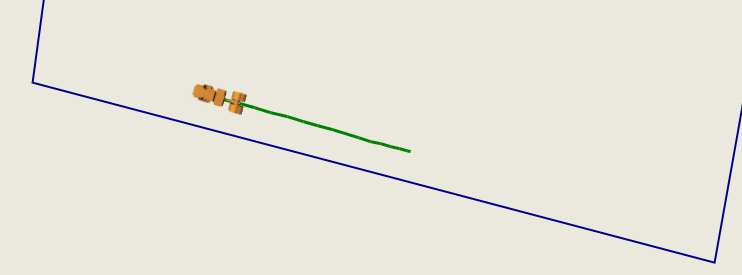
实现之后的效果如下图所示


 988
988

 被折叠的 条评论
为什么被折叠?
被折叠的 条评论
为什么被折叠?
 到【灌水乐园】发言


