


1.如果是“ATmega 8A-PU”和“ATmega 8PU-8PU”,因为IDE里没有直接支持8M的板子,所以要自己改造一下:
下载下面的文件,解压后放在hardware\arduino\bootloaders\optiboot目录下,并在hardware\arduino\boards.txt里添加如下信息:
01.##############################################################
02.
03.atmega8_8M.name=ATmega8_8MHz
04.
05.atmega8_8M.upload.protocol=arduino
06.atmega8_8M.upload.maximum_size=7168
07.atmega8_8M.upload.speed=115200
08.
09.atmega8_8M.bootloader.low_fuses=0xa4
10.atmega8_8M.bootloader.high_fuses=0xdc
11.atmega8_8M.bootloader.path=optiboot
12.atmega8_8M.bootloader.file=optiboot_atmega8_8M.hex
13.atmega8_8M.bootloader.unlock_bits=0x3F
14.atmega8_8M.bootloader.lock_bits=0x0F
15.
16.atmega8_8M.build.mcu=atmega8
17.atmega8_8M.build.f_cpu=8000000L
18.atmega8_8M.build.core=arduino
19.atmega8_8M.build.variant=standard
这时启动IDE,你就能在board里看到“Atmega8_8M”,选择他就对了。
2.如果是ATmega 8-16PU,在选板子时直接选择“arduino NG or w / ATmega 8“就可以了。
资源还在审核中,请谅解
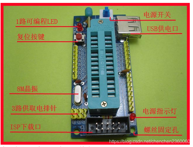
这个系统板的可编程led灯连接的是PD0,也就是Pin0.
让可编程led闪烁的代码如下
int led = 0;
void setup() {
pinMode(led, OUTPUT);
}
void loop() {
digitalWrite(led, HIGH); // turn the LED on (HIGH is the voltage level)
delay(1000); // wait for a second
digitalWrite(led, LOW); // turn the LED off by making the voltage LOW
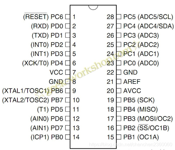
delay(1000); // wait for a second
}Atmega8引脚示意图:


 5685
5685

 被折叠的 条评论
为什么被折叠?
被折叠的 条评论
为什么被折叠?
 到【灌水乐园】发言


