


 8086微处理器在引脚33复位状态下工作于最大模式。最大模式涉及引脚24至31,如(RQ'/ GT 0)和(RQ'/ GT 1)用于总线请求和授予,LOCK'用于锁定内部总线,QS0和QS1指示队列状态,S2, S1和S0揭示CPU周期。"
132546569,19681023,使用R语言计算定性资料的频率与样本量,"['R语言', '统计分析']
8086微处理器在引脚33复位状态下工作于最大模式。最大模式涉及引脚24至31,如(RQ'/ GT 0)和(RQ'/ GT 1)用于总线请求和授予,LOCK'用于锁定内部总线,QS0和QS1指示队列状态,S2, S1和S0揭示CPU周期。"
132546569,19681023,使用R语言计算定性资料的频率与样本量,"['R语言', '统计分析']
微控制器,微处理器
When the pin 33 of the 8086 microprocessor is in the reset state, i.e. 0, then the microprocessor functions in the Maximum Mode.
当8086微处理器的引脚33处于复位状态(即0)时,则微处理器在最大模式下工作 。
The pins form 24 to 31 are dedicated to these modes. Let us have a look at how these pins function in the maximum mode of the 8086 microprocessor.
引脚形式24至31专用于这些模式。 让我们看一下这些引脚在8086微处理器的最大模式下如何工作。
最大模式引脚 (Maximum Mode pins)
(RQ' / GT 0) and (RQ’ / GT 1)
(RQ'/ GT 0)和(RQ'/ GT 1)
These two pins are used for bus request and grant purpose. Through these pins, a connection is established between the external peripheral devices and the 8086 microprocessor. Among these two pins, the pin- (RT / GT 0) has higher priority over (RT / GT 1).
这两个引脚用于总线请求和授予目的。 通过这些引脚,可以在外部外围设备和8086微处理器之间建立连接。 在这两个引脚中,引脚(RT / GT 0)的优先级高于(RT / GT 1)。
LOCK'
锁'
This pin is used to lock the internal buses of the microprocessor. When the control of buses is handed over to an external peripheral device, then the microprocessor is locked through this pin. It is an active low signal.
该引脚用于锁定微处理器的内部总线。 当总线控制权移交给外部外围设备时,微处理器将通过该引脚锁定。 这是一个低电平有效信号。
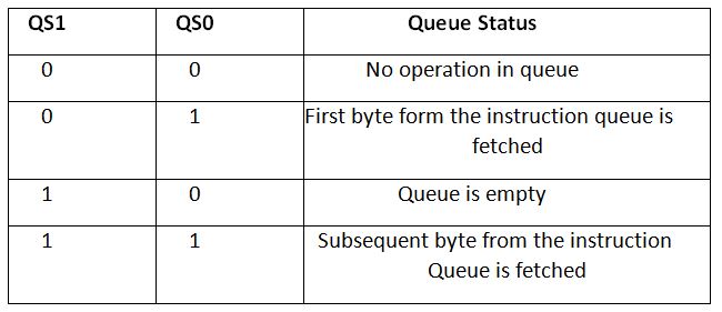
QS0 and QS1
QS0和QS1
QS stands for Queue status, and as the name suggests, these two pins are used to tell the status of the queue. The status of the queue form the values of these pins is decided as follows:
QS代表队列状态,顾名思义,这两个引脚用于指示队列状态。 这些引脚的值决定的队列状态如下:
S2, S1 and S0
S2,S1和S0
Here, the S in each of these pins stands for Status. These three pins: S2, S1, and S0 together tell about the CPU cycle. The different of the values of these pins taken together tell about which CPU cycle is currently running.
在此,每个引脚中的S代表状态。 这三个引脚:S2,S1和S0共同说明CPU周期。 这些引脚的值之和不同,可以表明当前正在运行哪个CPU周期。

翻译自: https://www.includehelp.com/embedded-system/maximum-mode-in-the-8086-microprocessor.aspx
微控制器,微处理器


 被折叠的 条评论
为什么被折叠?
被折叠的 条评论
为什么被折叠?
 到【灌水乐园】发言


