


串行加法器和并行加法器
Till now, we have already read (in the previous articles) about designing and uses of the basic form of adders and subtractors such as Half Adder, Full Adder, Half Subtractor, and Full Subtractor. In this article, we are going to learn about the more advanced concept of adders and subtractors and their design and uses using block diagrams and logic circuit diagrams.
到目前为止,我们已经阅读(在之前的文章中)有关加法器和减法器基本形式的设计和使用,例如Half Adder,Full Adder,Half Subtractor和Full Subtractor。 在本文中,我们将使用框图和逻辑电路图来学习加法器和减法器的更高级概念及其设计和使用。
并行二进制加法器 (Parallel Binary Adder)
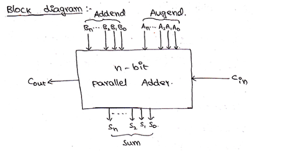
As, we already know, a full adder was used to add two 1-bit binary numbers and the additional carry bit (Cin). But, to add two n-bit binary numbers, we will require n-number of full adders. The addition of LSB bits can be done by using any of half-adder or a full-adder with Cin terminal grounded, but in practical parallel adders, we use a full-adder at the least significant stage also to facilitate cascading. The carry-out of each full-adder is also connected to the carry-in of the next full-adder in the higher-order. A parallel adder is used to add two numbers in parallel form and to produce the sum bits as parallel outputs. In two numbers, one is addend and the other is augend and both are added parallelly to get the sum.
正如我们已经知道的那样,使用了全加法器将两个1位二进制数和另一个进位( C in )相加。 但是,要添加两个n位二进制数,我们将需要n个完全加法器。 LSB位的加法可以通过在端子接地时使用半加法器或全加法器中的任何一个来完成,但在实际的并行加法器中,我们在最低有效级使用全加法器也有助于级联。 每个全加器的进位也连接到更高阶的下一个全加器的进位。 并行加法器用于以并行形式将两个数字相加,并产生总和位作为并行输出。 在两个数字中, 一个是加数,另一个是加数,并且两个都被并行相加以获得总和。
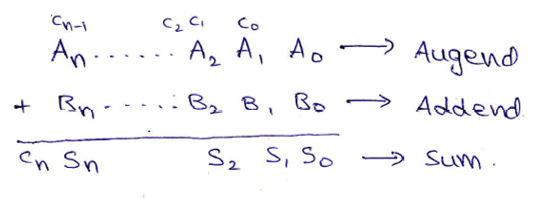
Two n+1-bit binary number A and B of the form,
两个n + 1位二进制数A和B的形式,
    A:      An An-1 An-2 ... A3 A2 A1 A0	    (Augend)
    B:      Bn Bn-1 Bn-2 ... B3 B2 B1 B0	    (Addend)
can be added as,
可以添加为
Block diagram and Logic circuit diagram of a Parallel Binary adder can be given as,
并行二进制加法器的框图和逻辑电路图可以表示为:

4位二进制加法器 (4-bit Binary Adder)
From the above-provided logic, we need 4 full adders connected together to add 4-bit binary numbers. For 4-bit binary numbers A and B of the form,
根据上面提供的逻辑,我们需要将4个全加器连接在一起以添加4位二进制数。 对于格式为4和2的二进制数A和B,
A: A3 A2 A1 A0 and B: B3 B2 B1 B0, its sum can be obtained as,
A: A 3 A 2 A 1 A 0和B: B 3 B 2 B 1 B 0 ,其总和可以得出,

Block diagram and Logic circuit diagram of a 4-bit Binary adder can be given as,
4位二进制加法器的框图和逻辑电路图可以表示为:


4位二进制减法器 (4-Bit Binary Subtractor)
We already know that two numbers A (Minuend) and B (Subtrahend) can be subtracted using 2s complement method, where,
我们已经知道,可以使用2s补码方法减去两个数字A (被减数)和B (被减数),其中,
    A – B   = A + 2s complement of B
            = A + 1s complement of B + 1
Thus, 4-bit binary numbers A and B can subtract as,
因此,4位二进制数A和B可以减去,

And the logic circuit for the same can be drawn as,
逻辑电路可以画为

Parallel Adder/Subtractor using a single circuit can be also designed using a Mod bit (M), where mod bit M decides whether the circuit will act as an adder or a subtractor. When M=0, then the circuit acts as an adder and when M=1, then the circuit acts as a subtractor. The circuit for the same can be drawn as,
也可以使用Mod位( M )设计使用单个电路的并行加法器/减法器,其中Mod位M决定该电路将充当加法器还是减法器。 当M = 0时 ,电路充当加法器,而当M = 1时 ,电路充当减法器。 相同的电路可以画成,
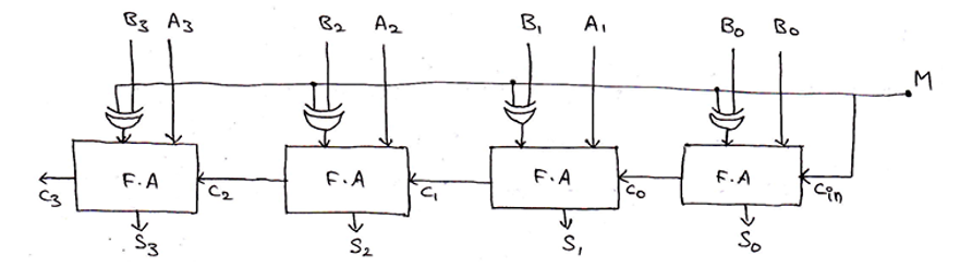
    When M=0,
    output  = A3 A2 A1 A0 + B3 B2 B1 B0 + Cin          [Since, A⊕0 = A]
            = A3 A2 A1 A0 + B3 B2 B1 B0 + 0
            = A + B
Thus, circuit acts as a 4-bit binary adder.
因此,电路用作4位二进制加法器。
    When M=1,
    output  = A3 A2 A1 A0 + B3 B2 B1 B0 + Cin
            = A3 A2 A1 A0 + B3 B2 B1 B0 + 1
            = A + B + 1
            = A – B
Thus, circuit acts as a 4-bit binary subtractor
因此,电路充当4位二进制减法器
翻译自: https://www.includehelp.com/basics/n-bit-parallel-adders-4-bit-binary-adder-and-subtractor.aspx
串行加法器和并行加法器


 3764
3764

 被折叠的 条评论
为什么被折叠?
被折叠的 条评论
为什么被折叠?
 到【灌水乐园】发言


