


linux 下的avr
程序使2个LED闪烁 (Program to blink 2 LEDs Alternatively)
#include<avr/io.h>

int main(void)
{
	DDRA=0x03;
	DDRD=0x00;

	while(1)
	{
		if((PIND & 0x01) == 0x01)
			PORTA=0x01;
		else
			PORTA=0x02;
	}
}
Explanation
说明
Here, DDRA = 0x03 indicates the input given to both our LEDs. The LEDs are connected in the terminal PA0 and PA1 i.e. the pin 0 & 1.
此处, DDRA = 0x03表示提供给两个LED的输入。 LED连接在端子PA0和PA1(即引脚0和1)上。
PINS:	7	6	5	4	3	2	1	0
INPUTS:	0	0	0	0	0	0	1	1
The input can be written in hexadecimal as 03. Therefore, we have written DDRA = 0x03.
输入可以十六进制形式写为03。因此,我们写了DDRA = 0x03 。
DDRD = 0x00 represents the input to the button which we have connected in the D port.
DDRD = 0x00表示我们在D端口中连接的按钮的输入。
Inside the IF statement we have represented the condition which says that when the button is pressed the input 1 will be given to the PORTA at the 0th PIN. i.e. LED 1 will glow.
在IF语句中我们已经表示它说,当按下该按钮,输入1将在0 号管脚被提供给PORTA的条件。 即LED 1将发光。
In the else condition we have given the statement such that when our Button won’t be pressed the LED 2 would Blink continuously.
在else条件下,我们给出了这样的声明:当不按下按钮时,LED 2将连续闪烁。
Simulation
模拟
Explanation
说明
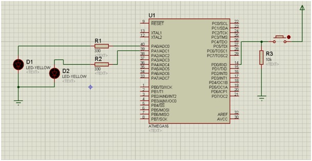
Components needed:
所需组件:
- 2 resistors (330 ohm)
- 2 LEDs
- ATmega16
- Button
- One resistor of 10k ohm value
- Power Terminal
- Two Ground Terminal
Arrange the components as shown in the above image.
如上图所示排列组件。
Here we have connected the resistance of 10k here because the current from the power terminal will always prefer a low resistance path, so instead of going to the ground it will go directly to the ATmega16.
在这里,我们在此处连接了10k的电阻,因为来自电源端子的电流将始终倾向于低电阻路径,因此,它直接流向ATmega16而不是接地。
While simulating the setup you will observe that when the Switch is OFF , LED 2 will glow continuously.
在模拟设置时,您会发现当开关为OFF时,LED 2会持续发光。
And when you press the button you will observe that the LED 1 will glow and LED 2 will stop glowing.
当您按下按钮时,您会发现LED 1会发光,LED 2会停止发光。
linux 下的avr


 被折叠的 条评论
为什么被折叠?
被折叠的 条评论
为什么被折叠?
 到【灌水乐园】发言


