


There are several ways to connect EIBD to the KNX bus. Here's the list coming from the EIBD homepage :
- FT1.2 / BCU 2
- PEI16 / BCU 1 (using the BCU 1 kernel driver or an experimental user mode driver)
- TPUART (The use of the TPUART kernel driver is supported, but the user mode implementation is simpler to use and lacks no features)
- EIBnet/IP Routing and Tunneling
- KNX on USB (only EMI1 and EMI2 are supported; CEMI is not really supported by current USB interfaces)
Solutions 2 and 3 are discouraged, because they rely on kernel drivers and porting these drivers to embedded platforms is not always straightforward.
The choice between the different solutions depends mainly on the device you have, money you are ready to spend and your skills at building some electronics.
Contents[hide] |
EIBnet/IP tunneling
Using a KNX/IP interface like Siemens N148/21, you can esaily connect EIBD to your domotic installation with just an ethernet cable.
Example eibd command:
eibd -d -D -S -T -i ipt:192.168.178.21:3671
KNX on USB
If your device running eibd has USB host ports, it should be possible to connect a KNX/USB interface to it.
Example eibd command:
usbport=$(findknxusb | /bin/sed -e '1 d' -e 's/device //' | /bin/cut -d':' -f1-2)
eibd  -d -D -S -T -i usb:$usbport
FT1.2 / BCU 2
A BCU is a KNX bus coupling unit. It has a KNX bus connector on one side and a 10 pole connector on the other side called PEI interface (with ground, +5V, Rx, Tx, ...). The BCU contains a microcontroller executing the KNX protocol stack and allowing (among others) serial communication on the PEI interface. With the new version of BCU called BCU2, a new protocol (called FT1.2) has been defined on the PEI interface. This new protocol only uses Rx and Tx (no RTS/CTS), and this allow it to be used with serial ports having only Rx and Tx.
Linksys WRT54G/GS/GL
The Linksys WRT54G(S) has no externally accessible RS232 interface. On the electronic board, there is a connector where you can find the Rx and Tx signals of the serial ports, but the electrical levels are 0V / 3V3 (while RS232 is +12V / -12V). With the signals on this connector, it's possible to connect a RS232 interface like the one described at http://www.rwhitby.net/projects/wrt54gs
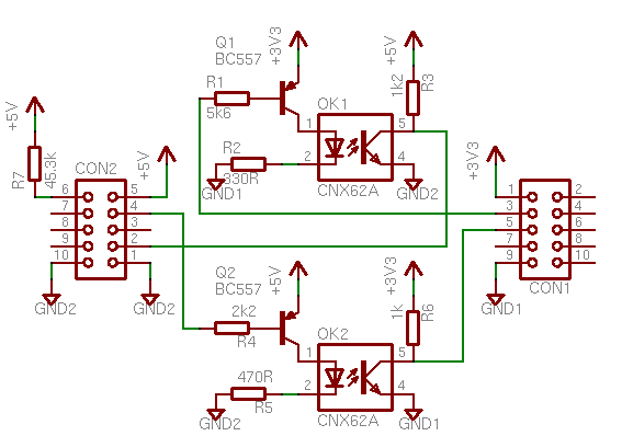
The role of the hardware I built is to adapt the serial signal between 3V3 of the Linksys router and the 5V signal of the BCU2. I used Optocouplers to ensure galvanic separation of the 2 systems.
Schematic of my hardware can be found here:
http://ouaye.net/linknx/bcu-interface/bcu-uart-interface.png
CON1 is the connector on linksys and CON2 on the PEI interface of BCU2
I also heard about a much simpler interface, simply using 2 resistor to achieve 45,3 kOhm needed to set the BCU in FT1.2 mode and connecting Rx of Linksys to Tx of BCU2 through a 1 kOhm resistor and Tx of Linksys to Rx of BCU2.
More details here (In German):
http://knx-user-forum.de/showpost.php?p=17261&postcount=116


 1660
1660


 被折叠的 条评论
为什么被折叠?
被折叠的 条评论
为什么被折叠?
 到【灌水乐园】发言


