


A fundamental concept in the design of the Berkeley networking code is the memory buffer, called an mbuf, used throughout the networking code to hold various pieces of information.
Mbuf Containing Socket Address Structure
In the call to sendto, the fifth argument points to an internet socket address structure(named serv)
if (sendto(sockfd, buff, BUFFSIZE, 0,
                   (struct sockaddr *) &serv, sizeof(serv)) != BUFFSIZE)
                perror("sendto error");
and the sixth argument specifies its length(which we’ll see later is 16 bytes). One of the first things done by the socket layer for this system call is to varify that these arguments are valid(i.e., the pointer points to a piece of memory in the adderess space of the process) and then copy the socket address structure into an mbuf. Figure below shows the resulting mbuf.
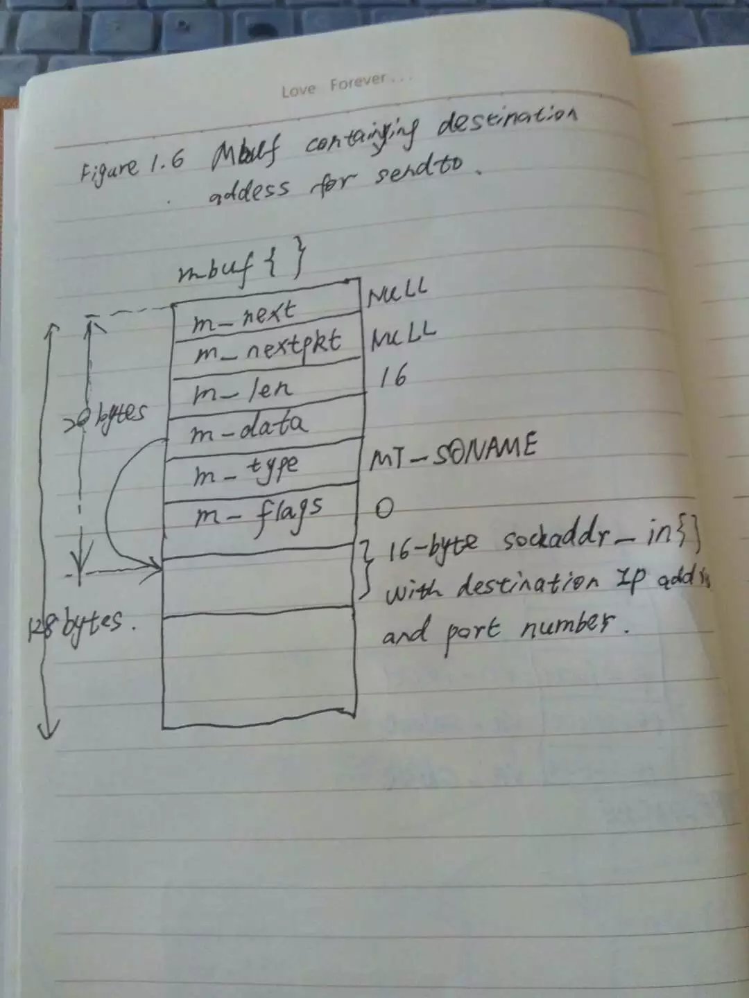
the first 20 bytes of the mbuf is a header containing information about the mbuf. This 20-byte header contains four 4-byte fields and two 2-byte fields. The total size of the mbuf is 128 bytes.
Mbufs can be linked together using the m_next and m_nextpkt members, as we’ll see shortly. Both are null pointers in this example, which is a stand-alone mbuf.
The m_data member points to the data in the mbuf and the m_len member specifies its length. For this example, m_data points to the first byte of data in the mbuf. The final 92 bytes of the mbuf data area are unused.
The m_type member specifies the type of data contained in the mbuf, which for this example is MT_SONAME(socket name). The final member in the header, m_flags, is zero in this example.
Mbuf Containing Data
continuing our example, the socket layer copies the data buffer specified in the call to sendto into one or more mbufs. The second argument to sendto specifies the start of the data buffer(buff), and the third argument is its size in bytes(150). Figure below shows how two mbufs hold the 150 bytes of data.
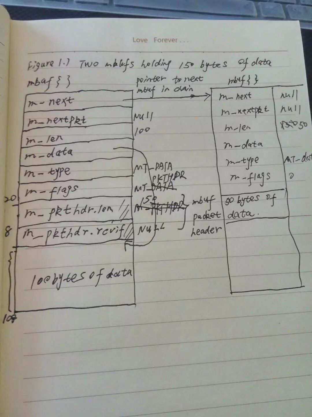
This arrangement is called an mbuf chain. The m_next member in each mbuf links together all the mbufs in a chain.
The next change we see is the addition of two members, m_pkthdr.len and m_pkthdr.rcvif, to the mbuf header in the first mbuf of the chain. These two members comprise the packet header and are used only in the first mbuf of a chain. The m_flags member contains the value M_PKTHDR to indicate that this mbuf contains a packet header. The len member of the packet header structure contains the total length of the mbuf chain(150 ), and the next member, rcvif, we’ll see later contains a pointer to the received interface structure for recefived packets.
One reason for maintaining a packet header with the total length in the first mbuf on the chain is to avoid having to go through all the mbufs on the chain to sum their m_len members when the total length is needed.
Prepending IP and UDP Headers
After the socket layer copies the destination socket address structure into an mbuf(Figure 1.6) and the data into an mbuf chain(Figure 1.7), the protocol layer correspongding to the socket descriptor ( a UDP socket) is called. S**pecifically, the UDP output routine is called and pointers to the mbufs that we’ve examined are passed as rguments**.
This routine needs to prepend an ip header and a udp header in front of the 150 bytes of data, fill in the headers, and pass the mbufs to the ip output routine.
The way that data is prepended to the mbuf chain in Figure 1.7 is to allocate another mbuf, make it the front of the chain, and copy the packet header from the mbuf with 100 bytes of data into the new mbuf. This gives us the three mbufs shown in Figure 1.8.
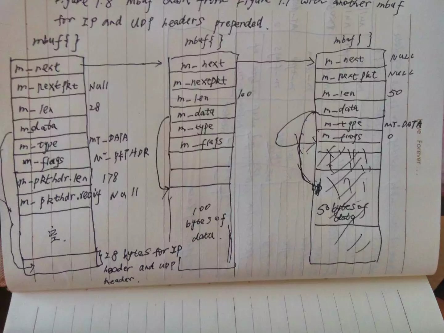
The ip header and udp header are stored at the end of the new mbuf that becomes the head of the chain.This allows for any lower-layer protocols(e.g., the interface layer) to prepend its header in front of the ip header if necessary, without having to copy the ip and the udp headers. The m_data pointer in the first mbuf points to the start of these two headers, and m_len is 28. Future headers that fit in the 72 bytes of unused space between the packet header and the ip header can be prepended before the ip header by adjusting the m_data pointer and the m_len accordingly. Shortly we’ll see that the ethernet header is built here in this fashion.
Notice that the packet header has been moved from the mbuf with 100 bytes of data into the new mbuf. The packet header must always be in the first mbuf on the chain. To accommodate this movement of the packet header, the M_PKTHDR flag is set in the first mbuf and cleared in the second mbuf. The space previously occupied by the packet header in the second mbuf is now unused. Finally, the length member in the packet header is incrmented by 28 bytes to become 178.
The udp checksum is calculated and stored in the udp header. Notice that this requires a complete pass of the 150 bytes of data stored in the mbuf chain.
So far the kernel has made two complete passes of the 150 bytes of user data: once to copy the data from the userś buffer into the kernelś mbufs, and now to calculate the udp checksum. Extra passes over the data can degrade the protocol’s performance, and in later chapters we describe alternative implementation techniques that avoid unnecessary passes.
At this point the udp output routine calls the ip output routine, passing a pointer to the mbuf chain for ip to output.
IP Output
The ip output routine fills in the remaining fields in the ip header including the ip checksum, determines the outgoing interface to which the datagram should be given(this is the ip routing function), fragements the ip datagram if necessary, and calls the interface output function.
Assuming the outgoing interface is an Ethernet, a general-purpose Ethernet output function is called, again with a pointer to the mbuf chain as an argument.
Ethernet Output
The first function of the ethernet output function is to convert the 32-bit ip address into its corresponding 48-bit ethernet address. This is done using ARP(address resolution protocol) and may involve sending an arp request on the ethernet and waiting for an arp reply. While this takes places, the mbuf chain to be output is held, waiting for the reply.
The ethenet output routine then prepends a 14-byte ethernet header to the first mbuf in the chain, immediately before the ip header. This contains the 6-byte ethernet destination adderess, 6-byte ethernet source address, and 2-byte ethernet frame type.
The mbuf chain is then added to the end of the output queue for the interface. If the interface is not currently busy, the interfaces’ start output routine is called directly. If the interface is busy, its output routine will process the new mbuf on its queue when it is finished with the buffers already on its output queue.
when the interface processes an mbuf that’s on its output queue, it copies the data to its transmit buffer and initiates the output. In our example, 192 bytes are copied to the transmit buffer: the 14-byte ethernet header, 20-byte ip header, 8-byte udp header, and 150 bytes of user data. This is the third complete pass of the data by the kernel. Once the data is copied from the mbuf chain into the device’s transmit buffer, the mbuf chain is released by the ethernet device driver. The three mbufs are put back into the kernel’s pool of free mbufs.
Summary of UDP Output
The figure below we give an overview of the processing that takes place when a process calls sendto to transmit a single udp datagram. The relationship of the processing that we have described to the three layers of kernel code is also shown.
summary of UDP output
Figure below we give an overview of the processing that takes place when a process calls sendto to transmit a single udp datagram. The relationship of the processing that we’ve described to the three layers of kernel code is also shown.
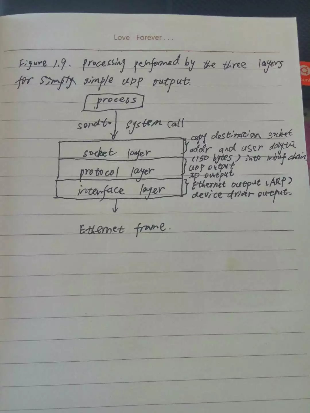
function calls pass control from the socket layer to the udp output routine, to the ip output routine. Each function call passes a pointer to the mbuf chain to be output. At the lowest layer, the device driver, the mbuf chain is placed on the device’s output queue and the device is started, if necessary. The function calls return in reverse order of their call, and eventually the system call returns to the process. Notice that there is no queueing of the udp data until it arrives at the device driver. The higher layers just prepend their header and pass the mbuf to the next lower layer.
At this point our program calls recvfrom to read the server’s reply. Since the input queue for the specified socket is empty(assuming the reply has not been received yet), the process is put to sleep.


 511
511

 被折叠的 条评论
为什么被折叠?
被折叠的 条评论
为什么被折叠?
 到【灌水乐园】发言


