


在此基础上
=========================================================================
属性
| Name | Description | 备注 |
| ActiveView | Gets the current active model view in read-only mode.NOTE: This property is a get-only property. Set is not implemented. | 以只读模式获取当前活动模型视图。注意:此属性是一个仅获取属性。 |
| ConfigurationManager | Gets the IConfigurationManager object, which allows access to a configuration in a model. | 获取 IConfigurationManager 对象,该对象允许访问模型中的配置。 |
| Extension | Gets the IModelDocExtension object, which also allows access to the model document. | 获取 IModelDocExtension 对象,该对象还允许访问模型文档。 |
| FeatureManager | Gets the IFeatureManager object, which allows access to the FeatureManager design tree. | 获取 IFeatureManager 对象,该对象允许访问 FeatureManager 设计树。 |
| FeatureManagerSplitterPosition | Splits the FeatureManager design tree and gets or sets the location of the split bar in the FeatureManager design tree panel. | 拆分 FeatureManager 设计树并获取或设置拆分条在 FeatureManager 设计树面板中的位置。 |
| IActiveView | Gets the current active model view in read-only mode.NOTE: This property is a get-only property. Set is not implemented. | 以只读模式获取当前活动模型视图。注意:此属性是一个仅获取属性。 |
| ILightSourcePropertyValues | Gets and sets the light source property values. | 获取和设置光源属性值。 |
| IMaterialPropertyValues | Gets or sets a material's properties in the active configuration. | 获取或设置活动配置中的材料属性。 |
| IPageSetup | Gets the page setup for this document. | 获取此文档的页面设置。 |
| ISelectionManager | Gets the ISelectionMgr object for this document, which makes the currently selected object available. | 获取此文档的 ISelectionMgr 对象,使当前选定的对象可用。 |
| LargeAssemblyMode | Gets or sets Large Assembly Mode for this document. | 获取或设置此文档的大型程序集模式。 |
| LengthUnit | Gets and sets the same LengthUnit value used by IModelDoc2::GetUnits, IModelDoc2::IGetUnits, and IModelDoc2::SetUnits. | 获取和设置 IModelDoc2::GetUnits、IModelDoc2::IGetUnits 和 IModelDoc2::SetUnits 使用的相同 LengthUnit 值。 |
| LightSourcePropertyValues | Gets and sets the light source property values. | 获取和设置光源属性值。 |
| LightSourceUserName | Gets or sets the light source name that is displayed in the SOLIDWORKS user interface. | 获取或设置在 SOLIDWORKS 用户界面中显示的光源名称。 |
| MaterialIdName | Gets or sets the material name. | 获取或设置材质名称。 |
| MaterialPropertyValues | Gets or sets a material's properties in the active configuration. | 获取或设置活动配置中的材料属性。 |
| MaterialUserName | Gets or sets the material name. | 获取或设置材质名称。 |
| ModelViewManager | Gets the IModelViewManager object, which allows access to the model view. | 获取 IModelViewManager 对象,该对象允许访问模型视图。 |
| PageSetup | Gets the page setup for this document. | 获取此文档的页面设置。 |
| Printer | Gets or sets the default printer for this document. | 获取或设置此文档的默认打印机。 |
| SceneBkgImageFileName | Controls the image filename used as the current background picture. | 控制用作当前背景图片的图像文件名。 |
| SceneName | Gets and sets the name of the scene. | 获取和设置场景的名称。 |
| SceneUserName | Gets and sets the user name of the scene. | 获取和设置场景的用户名。 |
| SelectionManager | Gets the ISelectionMgr object for this document, which makes the currently selected object available.NOTE: This property is a get-only property. Set is not implemented. | 获取此文档的 ISelectionMgr 对象,这使当前选定的对象可用。注意:此属性是一个仅获取属性。 |
| ShowFeatureErrorDialog | Gets or sets whether to display the feature error dialog. | 获取或设置是否显示特征错误对话框。 |
| SketchManager | Gets the sketch manager, which allows access to sketch-creation routines. | 获取草图管理器,它允许访问草图创建例程。 |
| SummaryInfo | Gets or sets file summary information for the SOLIDWORKS document. | 获取或设置 SOLIDWORKS 文档的文件摘要信息。 |
| Visible | Gets or sets the visibility of the active document. | 获取或设置活动文档的可见性。 |
ActiveView
        private void SW_Clear(object sender, RoutedEventArgs e)
        {
            //首先要打开软件,打开文档
            sld4Handler.ModelDoc = sld4Handler.SwApp.ActiveDoc;
            object obj=sld4Handler.ModelDoc.ActiveView;
            MessageBox.Show((obj as ModelView).Scale2.ToString());
        }
ConfigurationManager
        private void SW_Clear(object sender, RoutedEventArgs e)
        {
        //打开软件,打开文档
            ModelDoc2 model = ((ModelDoc2)(sld4Handler.SwApp.ActiveDoc));
            ConfigurationManager configurationManager = model.ConfigurationManager;
            Configuration configuration = configurationManager.ActiveConfiguration;
            configurationManager.AddConfiguration2("NewCfg","NewCommnet","",(int)swConfigurationOptions2_e.swConfigOption_DontActivate,"","",true);

        }
Extension
        private void SW_Clear(object sender, RoutedEventArgs e)
        {
            //打开软件,打开文档
            ModelDoc2 model = ((ModelDoc2)(sld4Handler.SwApp.ActiveDoc));
            ModelDocExtension modelDocExtension = model.Extension;
            if (!modelDocExtension.ViewDisplayRealView) MessageBox.Show("RealView Mode can not use");
        }
FeatureManager
        private void SW_Clear(object sender, RoutedEventArgs e)
        {
            //打开软件,打开文档,显示第一个特征命令名
            ModelDoc2 model = ((ModelDoc2)(sld4Handler.SwApp.ActiveDoc));
            FeatureManager featMgr = model.FeatureManager;
            MessageBox.Show(featMgr.FeatureName[0].ToString());
        }
ISelectionManager
        private void SW_Clear(object sender, RoutedEventArgs e)
        {
            //打开软件,打开文档
            ModelDoc2 model = ((ModelDoc2)(sld4Handler.SwApp.ActiveDoc));
            SelectionMgr selectionMgr = model.ISelectionManager;
            MessageBox.Show(selectionMgr.EnableSelection.ToString());
        }
LengthUnit
        private void SW_Clear(object sender, RoutedEventArgs e)
        {
            //打开软件,打开文档
            ModelDoc2 model = ((ModelDoc2)(sld4Handler.SwApp.ActiveDoc));
            MessageBox.Show(((swLengthUnit_e)model.LengthUnit).ToString());
        }
MaterialIdName
        private void SW_Clear(object sender, RoutedEventArgs e)
        {
            //打开软件,打开文档
            ModelDoc2 model = ((ModelDoc2)(sld4Handler.SwApp.ActiveDoc));
            MessageBox.Show(model.MaterialIdName);
        }
MaterialPropertyValues
        private void SW_Clear(object sender, RoutedEventArgs e)
        {
            //打开软件,打开文档
            ModelDoc2 model = ((ModelDoc2)(sld4Handler.SwApp.ActiveDoc));
            double[] values = (double[])model.MaterialPropertyValues;
            string s = "";
            s = "R:" + values[0] + "\n"+ "G:" + values[1] + "\n"+ "B:" + values[2] + "\n" + "环境:" + values[3] + "\n" + "扩散:" + values[4] + "\n"
                + "镜面反射:" + values[5] + "\n" + "光泽度:" + values[6] + "\n" + "透明度:" + values[7] + "\n" + "排放 :" + values[8] + "\n";
            MessageBox.Show(s);
        }
MaterialUserName
        private void SW_Clear(object sender, RoutedEventArgs e)
        {
            //打开软件,打开文档
            ModelDoc2 model = ((ModelDoc2)(sld4Handler.SwApp.ActiveDoc));
            MessageBox.Show(model.MaterialUserName);
        }
ModelViewManager
        private void SW_Clear(object sender, RoutedEventArgs e)
        {
            //打开软件,打开文档
            ModelDoc2 model = ((ModelDoc2)(sld4Handler.SwApp.ActiveDoc));
            ModelViewManager viewMgr = model.ModelViewManager;
            viewMgr.AddSnapShot("View Add");
        }
SelectionManager
        private void SW_Clear(object sender, RoutedEventArgs e)
        {
            //打开软件,打开文档
            ModelDoc2 model = ((ModelDoc2)(sld4Handler.SwApp.ActiveDoc));
            SelectionMgr selectionMgr = model.SelectionManager;
            if(selectionMgr.EnableSelection) MessageBox.Show("true");
        }
ShowFeatureErrorDialog
        private void SW_Clear(object sender, RoutedEventArgs e)
        {
            ModelDoc2 model = ((ModelDoc2)(sld4Handler.SwApp.ActiveDoc));
            if(model.ShowFeatureErrorDialog) MessageBox.Show("displays an error dialog");
            else MessageBox.Show("does not displays an error dialog");
        }
SketchManager
       private void SW_Clear(object sender, RoutedEventArgs e)
        {
            //打开软件,打开文档,打开草图,有直线
            ModelDoc2 model = ((ModelDoc2)(sld4Handler.SwApp.ActiveDoc));
            SketchManager sketchManager = model.SketchManager;
            MessageBox.Show(sketchManager.ActiveSketch.GetLineCount().ToString());
        }
SummaryInfo( System.int FieldId)
        private void SW_Clear(object sender, RoutedEventArgs e)
        {
            ModelDoc2 model = ((ModelDoc2)(sld4Handler.SwApp.ActiveDoc));
            MessageBox.Show(
             "  Title         = " + model.SummaryInfo[((int)swSummInfoField_e.swSumInfoTitle)] +"\n"+
            "  Subject       = " + model.SummaryInfo[((int)swSummInfoField_e.swSumInfoSubject)] + "\n" +
            "  Author        = " + model.SummaryInfo[((int)swSummInfoField_e.swSumInfoAuthor)] + "\n" +
            "  Keywords      = " + model.SummaryInfo[((int)swSummInfoField_e.swSumInfoKeywords)] + "\n" +
            "  Comment       = " + model.SummaryInfo[((int)swSummInfoField_e.swSumInfoComment)] + "\n" +
            "  Saved by      = " + model.SummaryInfo[((int)swSummInfoField_e.swSumInfoSavedBy)] + "\n" +
            "  Date created  = " + model.SummaryInfo[((int)swSummInfoField_e.swSumInfoCreateDate2)] + "\n" +
            "  Date saved    = " + model.SummaryInfo[((int)swSummInfoField_e.swSumInfoSaveDate2)] + "\n" +
             "  Date created  = " + model.SummaryInfo[((int)swSummInfoField_e.swSumInfoCreateDate)] + "\n" +
            "  Date saved    = " + model.SummaryInfo[((int)swSummInfoField_e.swSumInfoSaveDate)] + "\n" );
        }
Visible
        private void SW_Clear(object sender, RoutedEventArgs e)
        {
             //打开软件,打开文档,
            ModelDoc2 model = ((ModelDoc2)(sld4Handler.SwApp.ActiveDoc));
            model.Visible = !model.Visible;
        }
===================================================================================================
方法
| Name | Description | 备注 |
| ActivateSelectedFeature | Activates the selected feature for editing. | 激活选定的特征进行编辑。 |
| AddConfiguration3 | Adds a new configuration to this model document. | 向此模型文档添加新配置。 |
| AddDiameterDimension2 | Adds a diameter dimension at the specified location for the selected item. | 在选定项目的指定位置添加直径尺寸。 |
| AddDimension2 | Creates a display dimension at the specified location for selected entities. | 在选定实体的指定位置创建显示尺寸。 |
| AddFeatureMgrView3 | Adds the specified tab to the FeatureManager design tree view. | 将指定选项卡添加到 FeatureManager 设计树视图。 |
| AddHorizontalDimension2 | Creates a horizontal dimension for the currently selected entities at the specified location. | 在指定位置为当前选定的实体创建水平尺寸。 |
| AddIns | Displays the Add-In Manager dialog box. | 显示插件管理器对话框。 |
| AddLightSource | Adds a type of light source to a scene with the specified names. | 将一种光源类型添加到具有指定名称的场景中。 |
| AddLightSourceExtProperty | Stores a float, string, or integer value for the light source. | 存储光源的浮点数、字符串或整数值。 |
| AddLightToScene | Adds a light source to a scene. | 为场景添加光源。 |
| AddLoftSection | Adds a loft section to a blend feature. | 将放样部分添加到混合特征。 |
| AddPropertyExtension | Adds a property extension to this model. | 向此模型添加属性扩展。 |
| AddRadialDimension2 | Adds a radial dimension at the specified location for the selected item. | 在选定项目的指定位置添加径向尺寸。 |
| AddSceneExtProperty | Stores a float, string, or integer value for a scene. | 存储场景的浮点数、字符串或整数值。 |
| AddVerticalDimension2 | Creates a vertical dimension for the currently selected entities at the specified location. | 在指定位置为当前选定的实体创建垂直尺寸。 |
| AlignOrdinate | Aligns the selected group of ordinate dimensions. | 对齐选定的一组纵坐标尺寸。 |
| AlignParallelDimensions | Aligns the selected linear dimensions in a parallel fashion. | 以平行方式对齐选定的线性尺寸。 |
| BlankRefGeom | Hides the selected reference geometry in the graphics window. | 在图形窗口中隐藏选定的参考几何体。 |
| BlankSketch | Hides the selected sketches. | 隐藏选定的草图。 |
| BreakDimensionAlignment | Breaks the association of any selected dimensions belonging to an alignment group (parallel or collinear). | 中断属于对齐组(平行或共线)的任何选定尺寸的关联。 |
| ClearSelection2 | Clears the selection list. | 清除选择列表。 |
| ClearUndoList | Clears the undo list for this model document. | 清除此模型文档的撤消列表。 |
| Close | Not implemented. Use ISldWorks::CloseDoc. | 未实现。使用 ISldWorks::CloseDoc。 |
| CloseFamilyTable | Closes the design table currently being edited. | 关闭当前正在编辑的系列零件设计表。 |
| ClosePrintPreview | Closes the currently displayed Print Preview page for this document. | 关闭此文档当前显示的打印预览页面。 |
| ClosestDistance | Calculates the distance and closest points between two geometric objects. | 计算两个几何对象之间的距离和最近点。 |
| CreateArcByCenter | Creates an arc by center in this model document. | 在此模型文档中按中心创建圆弧。 |
| CreateCenterLineVB | Creates a center line from P1 to P2 and can be used in Visual Basic for Applications (VBA) and other forms of Basic that do not support SafeArrays. | 创建从 P1 到 P2 的中心线,可用于 Visual Basic for Applications (VBA) 和不支持 SafeArray 的其他形式的 Basic。 |
| CreateClippedSplines | Creates one or more sketch spline segments that are clipped against a given (x1, y1), (x2, y2) rectangle. This rectangle lies in the space of the active 2D sketch. | 创建一个或多个针对给定 (x1, y1), (x2, y2) 矩形裁剪的草图样条线段。该矩形位于活动二维草图的空间中。 |
| CreateGroup | Creates an annotation group from the currently selected annotations. | 从当前选定的注释创建注释组。 |
| DeActivateFeatureMgrView | Deactivates a tab in the FeatureManager design tree view. | 停用 FeatureManager 设计树视图中的选项卡。 |
| DebugCheckIgesGeom | Dumps a IGES geometry check. | 转储 IGES 几何检查。 |
| DeleteAllRelations | Deletes all existing relations. | 删除所有现有关系。 |
| DeleteBendTable | Deletes a bend table. | 删除折弯表。 |
| DeleteBkgImage | Deletes any background image. | 删除任何背景图像。 |
| DeleteConfiguration2 | Deletes a configuration. | 删除配置。 |
| DeleteDesignTable | Deletes the design table for this document, if one exists. | 删除此文档的系列零件设计表(如果存在)。 |
| DeleteFeatureMgrView | Removes the specified tab in the FeatureManager design tree. | 移除 FeatureManager 设计树中的指定选项卡。 |
| DeleteLightSource | Deletes a light source. | 删除光源。 |
| DeleteNamedView | Deletes the specified model view. | 删除指定的模型视图。 |
| DeriveSketch | Creates a derived sketch. | 创建派生草图。 |
| DeSelectByID | Removes the selected object from the selection list. | 从选择列表中删除选定的对象。 |
| DimPreferences | Sets dimension preferences. | 设置尺寸首选项。 |
| DissolveLibraryFeature | Dissolves the selected library features. | 融合选定的库特征。 |
| DissolveSketchText | Dissolves sketch text. | 溶解草图文本。 |
| DragTo | Drags the specified end point. | 拖动指定的终点。 |
| DrawLightIcons | Draws any visible light icons. | 绘制任何可见光图标。 |
| EditConfiguration3 | Edits the specified configuration. | 编辑指定的配置。 |
| EditCopy | Copies the currently selected items and places them in the clipboard. | 复制当前选定的项目并将它们放在剪贴板中。 |
| EditCut | Cuts the currently selected items and places them on the Microsoft Windows Clipboard. | 剪切当前选定的项目并将它们放在 Microsoft Windows 剪贴板上。 |
| EditDatumTargetSymbol | Edits a datum target symbol. | 编辑基准目标符号。 |
| EditDelete | Deletes the selected items. | 删除所选项目。 |
| EditOrdinate | Puts the currently selected ordinate dimension into edit mode so you could add more ordinate dimensions to this group. | 将当前选定的纵坐标尺寸置于编辑模式,以便您可以向该组添加更多纵坐标尺寸。 |
| EditRebuild3 | Rebuilds only those features that need to be rebuilt in the active configuration in the model. | 仅重建需要在模型的活动配置中重建的那些特征。 |
| EditRedo2 | Repeats the specified number of actions in this SOLIDWORKS session. | 在此 SOLIDWORKS 会话中重复指定数量的操作。 |
| EditRoute | Makes the last selected route the active route. | 使最后选择的路线成为活动路线。 |
| EditSeedFeat | Gets the pattern seed feature, based on the selected face, and displays the Edit Definition dialog for that feature. | 根据所选面获取图案种子特征,并显示该特征的“编辑定义”对话框。 |
| EditSketch | Allows the currently selected sketch to be edited. | 允许编辑当前选定的草图。 |
| EditSketchOrSingleSketchFeature | Edits a sketch or sketch feature. | 编辑草图或草图特征。 |
| EditSuppress2 | Suppresses the selected feature, the selected component, or the owning feature of the selected face. | 压缩选定特征、选定组件或选定面的所属特征。 |
| EditUndo2 | Undoes the specified number of actions in the active SOLIDWORKS session. | 在活动的 SOLIDWORKS 会话中撤消指定数量的操作。 |
| EditUnsuppress2 | Unsuppresses the selected feature or component. | 取消压缩选定的特征或组件。 |
| EditUnsuppressDependent2 | Unsuppresses the selected feature or component and their dependents. | 取消压缩选定的特征或零部件及其从属项。 |
| EntityProperties | Displays the Properties dialog for the selected edge or face. | 显示所选边或面的属性对话框。 |
| EnumModelViews | Gets the model views enumeration in this document. | 获取此文档中的模型视图枚举。 |
| FeatEdit | Puts the current feature into edit mode. | 将当前要素置于编辑模式。 |
| FeatEditDef | Displays the Feature Definition dialog and lets the user edit the values. | 显示“功能定义”对话框并让用户编辑值。 |
| FeatureByPositionReverse | Gets the nth from last feature in the document. | 获取文档中最后一个特征的第 n 个特征。 |
| FeatureChamfer | Creates a chamfer feature. | 创建倒角特征。 |
| FeatureReferenceCurve | Creates a reference curve feature from an array of curves. | 从曲线阵列创建参考曲线特征。 |
| FileSummaryInfo | Displays the File Summary Information dialog box for this file. | 显示此文件的“文件摘要信息”对话框。 |
| FirstFeature | Gets the first feature in the document. | 获取文档中的第一个特征。 |
| FontBold | Enables or disables bold font style in the selected notes, dimensions, and GTols. | 在选定的注释、尺寸和几何图形中启用或禁用粗体样式。 |
| FontFace | Changes the font face in the selected notes, dimensions, and GTols. | 更改所选注释、尺寸和几何图形中的字体。 |
| FontItalic | Enables or disables italic font style in the selected notes, dimensions, and GTols. | 在选定的注释、尺寸和几何图形中启用或禁用斜体字体样式。 |
| FontPoints | Changes the font height (specified in points) in the selected notes, dimensions, and GTols. | 更改所选注释、尺寸和几何图形中的字体高度(以磅为单位指定)。 |
| FontUnderline | Enables or disables underlining the selected notes, dimensions, and GTols. | 启用或禁用为所选注释、尺寸和几何公差加下划线。 |
| FontUnits | Changes font height (specified in current system units) in the selected notes, dimensions, and GTols. | 更改所选注释、尺寸和几何图形中的字体高度(以当前系统单位指定)。 |
| ForceRebuild3 | Forces a rebuild of all features in the active configuration in the model. | 强制重建模型中活动配置中的所有特征。 |
| ForceReleaseLocks | Releases the locks that a file system places on a file when it is opened and detaches that file from the file system. | 释放文件系统在打开文件时放置在文件上的锁,并从文件系统中分离该文件。 |
| GetAddToDB | Gets whether entities are added directly to the SOLIDWORKS database. | 获取实体是否直接添加到 SOLIDWORKS 数据库。 |
| GetAmbientLightProperties | Gets the ambient light properties for this model document. | 获取此模型文档的环境光属性。 |
| GetAngularUnits | Gets the current angular unit settings. | 获取当前的角度单位设置。 |
| GetArcCentersDisplayed | Gets whether the arc centers are displayed. | 获取是否显示圆弧中心。 |
| GetBendState | Gets the current bend state of a sheet metal part. | 获取钣金零件的当前折弯状态。 |
| GetBlockingState | Gets the current value of the SOLIDWORKS blocking state, within the range of values accessible by IModelDoc2::SetBlockingState. | 在 IModelDoc2::SetBlockingState 可访问的值范围内获取 SOLIDWORKS 阻塞状态的当前值。 |
| GetConfigurationByName | Gets the specified configuration. | 获取指定的配置。 |
| GetConfigurationCount | Gets the number of configurations. | 获取配置数量。 |
| GetConfigurationNames | Gets the names of the configurations in this document. | 获取本文档中配置的名称。 |
| GetConsiderLeadersAsLines | Gets whether the display data of a leader is included as lines when the lines are retrieved from a view or annotation in this document. | 获取从该文档的视图或注释中检索线时是否将引线的显示数据包含为线。 |
| GetCurrentCoordinateSystemName | Gets the name of the current coordinate system or an empty string for the default coordinate system. | 获取当前坐标系的名称或默认坐标系的空字符串。 |
| GetDefaultTextHeight | Gets the default text height in use for this document. | 获取用于此文档的默认文本高度。 |
| GetDesignTable | Gets the design table associated with this part or assembly document. | 获取与此零件或装配体文档关联的设计表。 |
| GetDirectionLightProperties | Gets the directional light properties. | 获取定向光属性。 |
| GetDisplayWhenAdded | Gets whether new sketch entities are displayed when created. | 获取创建时是否显示新草图实体。 |
| GetEntityName | Gets the name of the specified face, edge, or vertex. | 获取指定面、边或顶点的名称。 |
| GetEquationMgr | Gets the equation manager. | 获取方程管理器。 |
| GetExternalReferenceName | Gets the name of the externally referenced document (in the case of a join or mirrored part). | 获取外部引用文档的名称(在连接或镜像部件的情况下)。 |
| GetFeatureCount | Gets the number of features in this document. | 获取此文档中的特征数量。 |
| GetFeatureManagerWidth | Gets the width of the FeatureManager design tree. | 获取 FeatureManager 设计树的宽度。 |
| GetFirstAnnotation2 | Gets the first annotation in the model. | 获取模型中的第一个注释。 |
| GetFirstModelView | Gets the first view in a model document. | 获取模型文档中的第一个视图。 |
| GetGridSettings | Gets the current grid settings. | 获取当前的网格设置。 |
| GetLayerManager | Gets the layer manager for the current drawing document. | 获取当前绘图文档的图层管理器。 |
| GetLightSourceCount | Gets the number of light sources. | 获取光源的数量。 |
| GetLightSourceExtProperty | Gets a float, string, or integer value stored for the light source. | 获取为光源存储的浮点数、字符串或整数值。 |
| GetLightSourceIdFromName | Gets the ID of the specified light source. | 获取指定光源的 ID。 |
| GetLightSourceName | Gets the name of a light source used internally by the SOLIDWORKS application. | 获取 SOLIDWORKS 应用程序内部使用的光源的名称。 |
| GetLineCount | Gets the number of lines in the current sketch. | 获取当前草图中的线数。 |
| GetLines | Gets all of the lines in the current sketch. | 获取当前草图中的所有线条。 |
| GetModelViewNames | Gets a list containing the names of each model view in this document. | 获取包含此文档中每个模型视图名称的列表。 |
| GetNext | Gets the next document in the current SOLIDWORKS session. | 获取当前 SOLIDWORKS 会话中的下一个文档。 |
| GetNumDependencies | Gets the number of strings returned by IModelDoc2::GetDependencies2. | 获取 IModelDoc2::GetDependencies2 返回的字符串数。 |
| GetPathName | Gets the full path name for this document, including the file name. | 获取此文档的完整路径名,包括文件名。 |
| GetPointLightProperties | Gets point light properties. | 获取点光源属性。 |
| GetPopupMenuMode | Gets the current pop-up menu mode. | 获取当前弹出菜单模式。 |
| GetPropertyExtension | Gets the specified property extension on this model. | 获取此模型上的指定属性扩展。 |
| GetRayIntersectionsPoints | Gets the intersection point information generated by IModelDoc2::RayIntersections. | 获取由 IModelDoc2::RayIntersections 生成的交点信息。 |
| GetRayIntersectionsTopology | Gets the topology intersections generated by IModelDoc2::RayIntersections. | 获取由 IModelDoc2::RayIntersections 生成的拓扑交集。 |
| GetSaveFlag | Gets whether the document is currently dirty and needs to be saved. | 获取文档当前是否脏且需要保存。 |
| GetSceneBkgDIB | Gets background image as a LPDIBSECTION. | 获取背景图像作为 LPDIBSECTION。 |
| GetSceneExtProperty | Gets a float, string, or integer value stored for the scene. | 获取为场景存储的浮点数、字符串或整数值。 |
| GetSpotlightProperties | Gets the spotlight properties. | 获取聚光灯属性。 |
| GetStandardViewRotation | Gets the specified view orientation matrix with respect to the Front view. | 获取相对于前视图的指定视图方向矩阵。 |
| GetTessellationQuality | Gets the shaded-display image quality number for the current document. | 获取当前文档的着色显示图像质量编号。 |
| GetTitle | Gets the title of the document that appears in the active window's title bar. | 获取出现在活动窗口标题栏中的文档的标题。 |
| GetToolbarVisibility | Gets the visibility of a toolbar. | 获取工具栏的可见性。 |
| GetType | Gets the type of the document. | 获取文档的类型。 |
| GetUnits | Gets the current unit settings, fraction base, fraction value, and significant digits. | 获取当前单位设置、小数部分设置、分数值和有效数字、四舍五入等。 |
| GetUpdateStamp | Gets the current update stamp for this document. | 获取此文档的当前更新标记。 |
| GetUserUnit | Gets this document's units settings. | 获取此文档的单位设置。 |
| GetVisibilityOfConstructPlanes | Gets whether construction (reference) planes are currently visible. | 获取构造(参考)平面当前是否可见。 |
| GetZebraStripeData | Gets zebra line data. | 获取斑马线数据。 |
| HideComponent2 | Hides the selected component. | 隐藏选定的组件。 |
| HideCosmeticThread | Hides the selected cosmetic thread. | 隐藏选定的装饰线。 |
| HideDimension | Hides the selected dimension in this document. | 隐藏此文档中的选定维度。 |
| HideShowBodies | Sets whether to hide or show the bodies in the model. | 设置是隐藏还是显示模型中的实体。 |
| HideSolidBody | Hides the currently selected solid body. | 隐藏当前选定的实体。 |
| IAddConfiguration3 | Adds a new configuration to this model document. | 向此模型文档添加新配置。 |
| IAddDiameterDimension2 | Adds a diameter dimension at the specified location for the selected item. | 在选定项目的指定位置添加直径尺寸。 |
| IAddHorizontalDimension2 | Creates a horizontal dimension for the current selected entities at the specified location. | 在指定位置为当前选定的实体创建水平尺寸。 |
| IAddRadialDimension2 | Adds a radial dimension at the specified location for the selected item. | 在选定项目的指定位置添加径向尺寸。 |
| IAddVerticalDimension2 | Creates a vertical dimension for the currently selected entities at the specified location. | 在指定位置为当前选定的实体创建垂直尺寸。 |
| IClosestDistance | Calculates the distance and closest points between two geometric objects. | 计算两个几何对象之间的距离和最近点。 |
| ICreateArc2 | Creates an arc based on a center point, a start, an end point, and a direction. | 基于中心点、起点、终点和方向创建圆弧。 |
| ICreateCenterLine | Creates a center line from P1 to P2. | 创建从 P1 到 P2 的中心线。 |
| ICreateCircle2 | Creates a circle based on a center point and a point on the circle. | 基于圆心和圆上的点创建圆。 |
| ICreateCircleByRadius2 | Creates a circle based on a center point and a specified radius. | 基于中心点和指定半径创建一个圆。 |
| ICreateClippedSplines | Creates one or more sketch spline segments that are clipped against a given (x1, y1), (x2, y2) rectangle. This rectangle lies in the space of the active 2D sketch. | 创建一个或多个针对给定 (x1, y1), (x2, y2) 矩形裁剪的草图样条线段。该矩形位于活动二维草图的空间中。 |
| ICreateEllipse2 | Creates an ellipse using the specified center point and points. | 使用指定的中心点和点创建椭圆。 |
| ICreateEllipticalArc2 | Creates a partial ellipse given a center point, two points that specify the major and minor axis, and two points that define the elliptical start and end points. | 给定一个中心点、两个指定长轴和短轴的点以及两个定义椭圆起点和终点的点,创建一个部分椭圆。 |
| ICreateEllipticalArcByCenter | Creates an elliptical arc trimmed between two points. | 创建在两点之间修剪的椭圆弧。 |
| ICreateLine2 | Creates a sketch line in the currently active 2D or 3D sketch. | 在当前活动的 2D 或 3D 草图中创建草图线。 |
| IFeatureByPositionReverse | Gets the nth from last feature in the document. | 获取文档中最后一个特征的第 n 个特征。 |
| IFeatureReferenceCurve | Creates a reference curve feature from an array of curves. | 从曲线阵列创建参考曲线特征。 |
| IFirstFeature | Gets the first feature in the document. | 获取文档中的第一个特征。 |
| IGet3rdPartyStorage | Gets the IStream interface to the specified stream inside the SOLIDWORKS document. | 获取 SOLIDWORKS 文档中指定流的 IStream 接口。 |
| IGetActiveSketch2 | Gets the active sketch. | 获取活动草图。 |
| IGetAngularUnits | Gets the current angular unit settings. | 获取当前的角度单位设置。 |
| IGetConfigurationByName | Gets the specified configuration. | 获取指定的配置。 |
| IGetConfigurationNames | Gets the names of the configurations in this document. | 获取本文档中配置的名称。 |
| IGetDependencies2 | Gets all of the model's dependencies. | 获取模型的所有依赖项。 |
| IGetDesignTable | Gets the design table associated with this part or assembly document. | 获取与此零件或装配体文档关联的设计表。 |
| IGetEntityName | Gets the name of the specified face, edge, or vertex. | 获取指定面、边或顶点的名称。 |
| IGetFirstAnnotation2 | Gets the first annotation in the model. | 获取模型中的第一个注释。 |
| IGetFirstModelView | Gets the first view in a model document. | 获取模型文档中的第一个视图。 |
| IGetLayerManager | Gets the layer manager ofr the current drawing document. | 获取当前工程图文档的图层管理器。 |
| IGetLines | Gets all of the lines in the current sketch. | 获取当前草图中的所有线条。 |
| IGetModelViewNames | Gets a list containing the names of each model view in this document. | 获取包含此文档中每个模型视图名称的列表。 |
| IGetNext | Gets the next document in the current SOLIDWORKS session. | 获取当前 SOLIDWORKS 会话中的下一个文档。 |
| IGetNumDependencies2 | Gets the number of strings returned by IModelDoc2::IGetDependencies2. | 获取 IModelDoc2::IGetDependencies2 返回的字符串数。 |
| IGetRayIntersectionsPoints | Gets the intersection point information generated by IModelDoc2::IRayIntersections. | 获取由 IModelDoc2::IRayIntersections 生成的交点信息。 |
| IGetRayIntersectionsTopology | Gets the topology intersections generated by IModelDoc2::IRayIntersections. | 获取由 IModelDoc2::IRayIntersections 生成的拓扑交集。 |
| IGetStandardViewRotation | Gets the specified view orientation matrix with respect to the Front view. | 获取相对于前视图的指定视图方向矩阵。 |
| IGetUnits | Gets the current unit settings, fraction base, fraction value, and significant digits. | 获取当前单位设置、分数基数、分数值和有效数字。 |
| IGetUserUnit | Gets this document's units settings. | 获取此文档的单位设置。 |
| IGetVersionHistoryCount | Gets the size of the array required to hold data returend by IModleDoc2::IVersionHistory. | 通过 IModleDoc2::IVersionHistory 获取保存数据返回所需的数组大小。 |
| IInsertDatumTag2 | Inserts a datum tag symbol at the selected location. | 在选定位置插入基准标记符号。 |
| IInsertGtol | Creates a new geometric tolerance symbol (GTol) in this document. | 在本文档中创建新的几何公差符号 (GTol)。 |
| IInsertNote | Inserts a note in this document. | 在此文档中插入注释。 |
| IInsertProjectedSketch2 | Projects the selected sketch items from the current sketch onto a selected surface. | 将当前草图中的选定草图项目投影到选定曲面上。 |
| IInsertSketchForEdgeFlange | Inserts a sketch for IFeatureManager::InsertSheetMetalEdgeFlange2 in this sheet metal part. | 在此钣金零件中插入 IFeatureManager::InsertSheetMetalEdgeFlange2 的草图。 |
| IInsertSketchText | Inserts sketch text. | 插入草图文本。 |
| IInsertWeldSymbol3 | Inserts a weld symbol into the model. | 将焊接符号插入模型中。 |
| IListAuxiliaryExternalFileReferences | Gets the names of auxiliary external file references for this model. | 获取此模型的辅助外部文件引用的名称。 |
| IMultiSelectByRay | Selects multiple objects of the specified type that are intersected by a ray from point (x,y,z in meters) in direction vector (x,y,z) within a distance radius. | 选择指定类型的多个对象,这些对象与距离半径内方向向量 (x,y,z) 中的点 (x,y,z 以米为单位) 的射线相交。 |
| Insert3DSplineCurve | Inserts a 3D-spline curve through the selected reference points. | 通过选定的参考点插入 3D 样条曲线。 |
| InsertAxis2 | Inserts a reference axis based on the currently selected items with an option to automatically size the axis. | 根据当前选定的项目插入参考轴,并带有自动调整轴大小的选项。 |
| InsertBendTableEdit | Inserts a bend table and puts the bend table into its edit state. | 插入折弯表并将折弯表置于其编辑状态。 |
| InsertBendTableNew | Inserts a new bend table into the model document. | 在模型文档中插入一个新的折弯表。 |
| InsertBendTableOpen | Inserts an existing bend table from a file into this model document. | 将文件中的现有折弯表插入到此模型文档中。 |
| InsertBkgImage | Inserts the scene background image. | 插入场景背景图像。 |
| InsertCompositeCurve | Inserts a composite curve based on selections. | 根据选择插入复合曲线。 |
| InsertConnectionPoint | Adds a connection point based on the selected point and selected planar item. | 添加基于选定点和选定平面项目的连接点。 |
| InsertCurveFile | Creates a curve. | 创建曲线。 |
| InsertCurveFileBegin | Creates a curve. | 创建曲线。 |
| InsertCurveFileEnd | Creates a curve. | 创建曲线。 |
| InsertCurveFilePoint | Creates a point for a curve. | 为曲线创建一个点。 |
| InsertDatumTag2 | Inserts a datum tag symbol at a selected location. | 在选定位置插入基准标记符号。 |
| InsertDome | Inserts a dome. | 插入圆顶。 |
| InsertExtendSurface | Extends a surface along the selected faces or edges. | 沿选定的面或边延伸曲面。 |
| InsertFamilyTableEdit | Edits an open design table from Microsoft Excel. | 从 Microsoft Excel 编辑打开的系列零件设计表。 |
| InsertFamilyTableNew | Inserts an existing design table from the model into the selected drawing view. | 将模型中的现有系列零件设计表插入到选定的图纸视图中。 |
| InsertFamilyTableOpen | Inserts the specified Microsoft Excel design table. | 插入指定的 Microsoft Excel 系列零件设计表。 |
| InsertFeatureReplaceFace | Creates a Replace Face feature. | 创建替换面孔功能。 |
| InsertFeatureShell | Creates a shell feature. | 创建壳特征。 |
| InsertFeatureShellAddThickness | Adds thickness to a face in a multi-thickness shell feature. | 在多厚度壳特征中为面添加厚度。 |
| InsertGtol | Creates a new geometric tolerance symbol (GTol) in this document. | 在本文档中创建新的几何公差符号 (GTol)。 |
| InsertHatchedFace | Hatches the selected faces or closed sketch segments in a drawing. | 在工程图中填充选定的面或闭合的草图线段。 |
| InsertHelix | Creates a constant-pitch helix or spiral. | 创建恒定螺距的螺旋线或螺旋线。 |
| InsertLoftRefSurface2 | Creates a loft surface from the selected profiles, centerline, and guide curves. | 从选定的轮廓、中心线和引导曲线创建放样曲面。 |
| InsertNewNote3 | Creates a new note. | 创建新笔记。 |
| InsertNote | Inserts a note in this document. | 在此文档中插入注释。 |
| InsertObject | Activates the Microsoft Insert Object dialog. | 激活 Microsoft 插入对象对话框。 |
| InsertOffsetSurface | Inserts an offset surface. | 插入偏移曲面。 |
| InsertPlanarRefSurface | Inserts a planar reference surface. | 插入平面参考曲面。 |
| InsertPoint | Inserts a point in this model document. | 在此模型文档中插入一个点。 |
| InsertRadiateSurface | Creates a radiate surface based on the selections. | 根据选择创建辐射表面。 |
| InsertRefPoint | Inserts a reference point based on the current selections. | 根据当前选择插入参考点。 |
| InsertRip | Creates a rip feature. | 创建撕裂特征。 |
| InsertRoutePoint | Adds a route point based on the selected point. | 根据所选点添加航路点。 |
| InsertSheetMetalBreakCorner | Inserts a break corner into a sheet metal part. | 在钣金零件中插入断角。 |
| InsertSheetMetalClosedCorner | Inserts a sheet metal closed corner into this model document. | 将钣金封闭角插入此模型文档中。 |
| InsertSheetMetalFold | Inserts a fold feature at the selected objects. | 在选定对象处插入折叠特征。 |
| InsertSheetMetalJog | Inserts a sheet metal jog in the current model document. | 在当前模型文档中插入钣金折弯。 |
| InsertSheetMetalUnfold | Inserts an unfold feature at the selected objects. | 在选定对象处插入展开特征。 |
| InsertSketchForEdgeFlange | Inserts a sketch for IFeatureManager::InsertSheetMetalEdgeFlange2 in this sheet metal part. | 在此钣金零件中插入 IFeatureManager::InsertSheetMetalEdgeFlange2 的草图。 |
| InsertSketchPicture | Inserts a picture into the current sketch. | 将图片插入当前草图。 |
| InsertSketchPictureData | Inserts a picture into the current sketch. | 将图片插入当前草图。 |
| InsertSketchPictureDatax64 | Inserts a picture into the current sketch in 64-bit applications. | 在 64 位应用程序中将图片插入当前草图。 |
| InsertSketchText | Inserts sketch text. | 插入草图文本。 |
| InsertSplinePoint | Inserts a spline point. | 插入样条点。 |
| InsertSplitLineProject | Splits a face by projecting sketch lines onto the face. | 通过将草图线投影到面上来分割面。 |
| InsertSplitLineSil | Splits a face by creating split lines along the silhouette of the selected faces. | 通过沿选定面的轮廓创建分割线来分割面。 |
| InsertWeldSymbol3 | Inserts a weld symbol into the model. | 将焊接符号插入模型中。 |
| InspectCurvature | Adds curvature combs to the selected sketch segment. | 将曲率梳添加到选定的草图线段。 |
| IParameter | Gets the specified parameter. | 获取指定的参数。 |
| IRelease3rdPartyStorage | Closes the specified storage stream. | 关闭指定的存储流。 |
| IsActive | Gets whether the specified assembly component is shown or hidden in this model document. | 获取在此模型文档中是显示还是隐藏指定的装配组件。 |
| IsEditingSelf | Gets whether this model is being edited in the context of another document. | 获取是否正在另一个文档的上下文中编辑此模型。 |
| ISetAngularUnits | Sets the current angular units. | 设置当前的角度单位。 |
| ISetNextSelectionGroupId | Sets the group ID for all remaining selections. | 为所有剩余选择设置组 ID。 |
| ISketchSplineByEqnParams | Creates a spline on the active 2D sketch using the specified b-curve parameters. | 使用指定的 b 曲线参数在活动 2D 草图上创建样条曲线。 |
| IsLightLockedToModel | Gets whether the specified light is fixed. | 获取指定的灯光是否固定。 |
| IsOpenedReadOnly | Gets whether a SOLIDWORKS document is open in read-only mode. | 获取 SOLIDWORKS 文档是否以只读模式打开。 |
| IsOpenedViewOnly | Gets whether a SOLIDWORKS document is open in view-only mode. | 获取 SOLIDWORKS 文档是否在仅查看模式下打开。 |
| IsTessellationValid | Gets whether the current set of facets is valid. | 获取当前的刻面集是否有效。 |
| IVersionHistory | Gets an array of strings indicating the versions in which this model document was saved, including the SOLIDWORKS version in which the model document is currently opened and which is the last value returned in the array. | 获取一个字符串数组,指示保存此模型文档的版本,包括当前打开模型文档的 SOLIDWORKS 版本以及数组中返回的最后一个值。 |
| LBDownAt | Generates a left mouse button press (down) event. | 生成鼠标左键按下(按下)事件。 |
| LBUpAt | Generates a left-mouse button release (up) event. | 生成鼠标左键释放(向上)事件。 |
| ListAuxiliaryExternalFileReferences | Gets the names of auxiliary external file references for this model. | 获取此模型的辅助外部文件引用的名称。 |
| ListAuxiliaryExternalFileReferencesCount | Gets the number of auxiliary external file references for this model. | 获取此模型的辅助外部文件引用数。 |
| Lock | Blocks the modifying commands in the user interface, effectively locking the application. | 阻止用户界面中的修改命令,有效地锁定应用程序。 |
| LockAllExternalReferences | Locks all external references. | 锁定所有外部参考。 |
| LockLightToModel | Locks or unlocks the specified light. | 锁定或解锁指定的灯。 |
| MoldDraftAnalysis | Performs a mold draft analysis. | 执行模具拔模分析。 |
| MultiSelectByRay | Selects multiple objects of the specified type that are intersected by a ray from point (x,y,z in meters) in direction vector (x,y,z) within a distance radius. | 选择指定类型的多个对象,这些对象与距离半径内方向向量 (x,y,z) 中的点 (x,y,z 以米为单位) 的射线相交。 |
| NameView | Creates a named view using the current view. | 使用当前视图创建命名视图。 |
| ObjectDisplayAsIcon | Shows the current OLE object as an icon. | 将当前 OLE 对象显示为图标。 |
| ObjectDisplayContent | Shows the current OLE object's content. | 显示当前 OLE 对象的内容。 |
| ObjectResetsize | Sets the size of the current OLE object to the default. | 将当前 OLE 对象的大小设置为默认值。 |
| Parameter | Gets the specified parameter. | 获取指定的参数。 |
| ParentChildRelationship | Shows the Parent/Child Relationships dialog for the selected feature. | 显示所选功能的父/子关系对话框。 |
| Paste | Pastes the contents of the Microsoft Windows Clipboard at the current insertion point. | 在当前插入点粘贴 Microsoft Windows 剪贴板的内容。 |
| PrintDirect | Prints the current document to the default printer. | 将当前文档打印到默认打印机。 |
| PrintPreview | Displays the Print Preview page for the current document. | 显示当前文档的打印预览页面。 |
| PropertySheet | Displays the the selected object's property sheet. | 显示选定对象的属性表。 |
| Quit | Closes the active document without saving changes (see Remarks). | 关闭活动文档而不保存更改(请参阅备注)。 |
| ReattachOrdinate | Reattaches an ordinate dimension to a different entity. | 将纵坐标尺寸重新附加到不同的实体。 |
| ReloadOrReplace | Reloads or replaces the current model document. | 重新加载或替换当前模型文档。 |
| RemoveGroups | Removes any annotation groups in the current selection. | 删除当前选择中的任何注释组。 |
| RemoveInspectCurvature | Removes curvature combs from the selected curved sketch segment. | 从选定的曲线草图线段中移除曲率梳。 |
| RemoveItemsFromGroup | Removes the selected annotations from their annotation groups. | 从其注释组中删除选定的注释。 |
| ResetBlockingState | Resets the blocking state for the SOLIDWORKS menus. | 重置 SOLIDWORKS 菜单的阻止状态。 |
| ResetLightSourceExtProperty | Resets the properties for a light source. | 重置光源的属性。 |
| ResetPropertyExtension | Clears all values stored in the property extension. | 清除存储在属性扩展中的所有值。 |
| ResetSceneExtProperty | Resets the extension property for a scene. | 重置场景的扩展属性。 |
| Save3 | Saves the current document. | 保存当前文档。 |
| SaveBMP | Saves the current view as a bitmap (BMP) file. | 将当前视图另存为位图 (BMP) 文件。 |
| Scale | Scales the part. | 缩放零件。 |
| ScreenRotate | Switches between model and screen center rotation. | 在模型和屏幕中心旋转之间切换。 |
| SelectedEdgeProperties | Sets the property values of the selected edge. | 设置选定边的属性值。 |
| SelectedFaceProperties | Sets the material property values of the selected face. | 设置选定面的材料属性值。 |
| SelectedFeatureProperties | Sets the property values of the selected feature. | 设置所选要素的属性值。 |
| SelectLoop | Selects the loop that corresponds to the selected edge. | 选择与选定边相对应的循环。 |
| SelectMidpoint | Puts the midpoint (swSelMIDPOINTS) of that edge on the selection list and removes the edge from the selection list when an edge is selected. | 将该边的中点 (swSelMIDPOINTS) 放在选择列表中,并在选择一条边时从选择列表中删除该边。 |
| SelectTangency | Selects all faces tangent to the selected face. | 选择与选定面相切的所有面。 |
| SetAmbientLightProperties | Sets ambient light properties. | 设置环境光属性。 |
| SetAngularUnits | Sets the current angular units. | 设置当前的角度单位。 |
| SetArcCentersDisplayed | Sets the current arc centers displayed setting. | 设置当前显示的圆弧中心设置。 |
| SetBendState | Sets the bend state of a sheet metal part. | 设置钣金零件的折弯状态。 |
| SetBlockingState | Sets the blocking state for the SOLIDWORKS menus. | 设置 SOLIDWORKS 菜单的阻塞状态。 |
| SetConsiderLeadersAsLines | Sets a flag on the document that indicates whether the display data of a leader should be included as lines when the lines are retrieved from a view or annotation in this document. | 在文档上设置一个标志,指示当从该文档的视图或注释中检索线时,是否应将引线的显示数据包括为线。 |
| SetDirectionLightProperties | Sets direction light properties. | 设置方向光属性。 |
| SetFeatureManagerWidth | Sets the width of the FeatureManager design tree. | 设置 FeatureManager 设计树的宽度。 |
| SetLightSourceName | Sets the light source name used internally by the SOLIDWORKS software. | 设置 SOLIDWORKS 软件内部使用的光源名称。 |
| SetLightSourcePropertyValuesVB | Sets the light source property values. | 设置光源属性值。 |
| SetParamValue | Sets the value of selected dimension (or parameter). | 设置选定尺寸(或参数)的值。 |
| SetPickMode | Returns the user to the default selection mode. | 将用户返回到默认选择模式。 |
| SetPointLightProperties | Sets point light properties. | 设置点光源属性。 |
| SetPopupMenuMode | Sets the pop-up menu mode. | 设置弹出菜单模式。 |
| SetReadOnlyState | Sets whether this document is read-only or read-write. | 设置此文档是只读还是读写。 |
| SetSaveAsFileName | Sets the Save As filename from within the FileSaveAsNotify2 event handlers, thereby, bypassing the Save As dialog. | 从 FileSaveAsNotify2 事件处理程序中设置另存为文件名,从而绕过“另存为”对话框。 |
| SetSaveFlag | Flags the document as dirty. | 将文档标记为脏。 |
| SetSceneBkgDIB | Sets background image described by DIBSECTION data. | 设置由 DIBSECTION 数据描述的背景图像。 |
| SetSpotlightProperties | Sets the spotlight properties. | 设置聚光灯属性。 |
| SetTessellationQuality | Sets the shaded-display image quality number for the current document. | 设置当前文档的阴影显示图像质量编号。 |
| SetTitle2 | Sets the title of a new document. | 设置新文档的标题。仅对尚未保存的新文档有效。 |
| SetToolbarVisibility | Sets the visibility of a toolbar. | 设置工具栏的可见性。 |
| SetUnits | Sets the units used by the end-user for the model. | 设置最终用户为模型使用的单位。 |
| SetZebraStripeData | Sets the zebra-line data. | 设置斑马线数据。 |
| ShowComponent2 | Shows the selected component. | 显示选定的组件。 |
| ShowConfiguration2 | Shows the named configuration by switching to that configuration and making it the active configuration. | 通过切换到该配置并使其成为活动配置来显示命名配置。 |
| ShowCosmeticThread | Shows the selected cosmetic thread. | 显示选定的装饰线。 |
| ShowNamedView2 | Shows the specified view. | 显示指定的视图。 |
| ShowSolidBody | Shows the selected solid body. | 显示选定的实体。 |
| Sketch3DIntersections | Creates new sketch segments based on the selected surfaces. | 基于选定的曲面创建新的草图线段。 |
| SketchAddConstraints | Adds the specified constraint to the selected entities. | 将指定的约束添加到选定的实体。 |
| SketchAlign | Aligns the selected sketch entities. | 对齐选定的草图实体。 |
| SketchArc | Creates an arc in the current model document. | 在当前模型文档中创建圆弧。 |
| SketchCenterline | Adds a centerline to the current model document. | 向当前模型文档添加中心线。 |
| SketchConstrainCoincident | Makes the selected sketch entities coincident. | 使选定的草图实体重合。 |
| SketchConstrainConcentric | Makes the selected sketch entities concentric. | 使选定的草图实体同心。 |
| SketchConstrainParallel | Makes the selected sketch entities parallel. | 使选定的草图实体平行。 |
| SketchConstrainPerp | Makes the selected sketch entities perpendicular. | 使选定的草图实体垂直。 |
| SketchConstrainTangent | Makes the selected entities tangent. | 使选定的实体相切。 |
| SketchConstraintsDel | Deletes the specified relationship (constraint) on the currently selected sketch item. | 删除当前选定草图项目上的指定关系(约束)。 |
| SketchConstraintsDelAll | Deletes all of the constraints on the currently selected sketch segment. | 删除当前选定草图线段上的所有约束。 |
| SketchConvertIsoCurves | Converts ISO-parametric curves on a selected surface into a sketch entity. | 将选定曲面上的 ISO 参数曲线转换为草图实体。 |
| SketchMirror | Creates new entities that are mirror images of the selected entities. | 创建作为所选实体的镜像的新实体。 |
| SketchModifyFlip | Flips the the active or selected sketch about the specified coordinate system axis. | 围绕指定坐标系轴翻转活动或选定草图。 |
| SketchModifyRotate | Rotates the coordinate system of the active or selected sketch. | 旋转活动或选定草图的坐标系。 |
| SketchModifyScale | Scales the active or selected sketch. | 缩放活动或选定的草图。 |
| SketchModifyTranslate | Translates the coordinate system of the active or selected sketch. | 平移活动或选定草图的坐标系。 |
| SketchOffsetEdges | Offsets the edges of the selected entities. | 偏移选定实体的边缘。 |
| SketchOffsetEntities2 | Generates entities in the active sketch by offsetting the selected geometry by the specified amount. | 通过按指定量偏移选定几何体,在活动草图中生成实体。 |
| SketchSpline | Starts a spline, or continues one, using the specified point. | 使用指定的点开始一条样条曲线,或继续一条样条曲线。 |
| SketchTangentArc | Creates a tangent arc in the current model document. | 在当前模型文档中创建一个切线弧。 |
| SketchUndo | Undoes the last sketch command. | 撤消上一个草图命令。 |
| SketchUseEdgeCtrline | Uses this centerline in sketch. | 在草图中使用此中心线。 |
| SkToolsAutoConstr | Automatically constrains the active sketch. | 自动约束活动草图。 |
| Toolbars | Turns the specified SOLIDWORKS toolbars on and off. | 打开和关闭指定的 SOLIDWORKS 工具栏。 |
| ToolsDistance | Computes distance. | 计算距离。 |
| ToolsGrid | Shows and hides the grid in this model document. | 显示和隐藏此模型文档中的网格。 |
| ToolsMacro | Not implemented. | 未实现。 |
| ToolsMassProps | Calculates the mass properties. | 计算质量属性。 |
| ToolsSketchScale | Scales a sketch. | 缩放草图。 |
| ToolsSketchTranslate | Translates a sketch. | 翻译草图。 |
| UnBlankRefGeom | Shows the selected, hidden reference geometry in the graphics window. | 在图形窗口中显示选定的、隐藏的参考几何体。 |
| UnblankSketch | Shows a hidden sketch. | 显示隐藏的草图。 |
| UnderiveSketch | Changes a sketch to underived. | 将草图更改为未派生。 |
| UnLock | Reverses IModelDoc2::Lock and changes the status bar message to Process Complete. | 反转 IModelDoc2::Lock 并将状态栏消息更改为 Process Complete。 |
| UnlockAllExternalReferences | Unlocks all external references. | 解锁所有外部参考。 |
| UserFavors | Specifies whether geometric relations are automatically created as you add sketch entities. | 指定在您添加草图实体时是否自动创建几何关系。 |
| VersionHistory | Gets an array of strings indicating the versions in which this document was saved, including the SOLIDWORKS version in which the model document is currently opened and which is the last value returned in the array. | 获取指示保存此文档的版本的字符串数组,包括当前打开模型文档的 SOLIDWORKS 版本以及数组中返回的最后一个值。 |
| ViewConstraint | Shows the constraints for the current model document. | 显示当前模型文档的约束。 |
| ViewDispCoordinateSystems | Toggles the display of coordinate systems on and off. | 打开和关闭坐标系的显示。 |
| ViewDisplayCurvature | Toggles the display of surface curvature on and off. | 打开和关闭曲面曲率的显示。 |
| ViewDisplayFaceted | Sets the current display mode to show the facets that make up a shaded picture of STL output. | 设置当前显示模式以显示构成 STL 输出阴影图片的面。 |
| ViewDisplayHiddengreyed | Sets the current display mode to Hidden Lines Visible. | 将当前显示模式设置为隐藏线可见。 |
| ViewDisplayHiddenremoved | Sets the current display mode to Hidden Lines Removed. | 将当前显示模式设置为隐藏线已删除。 |
| ViewDisplayShaded | Sets the current display mode to Shaded. | 将当前显示模式设置为阴影。 |
| ViewDisplayWireframe | Sets the current display mode to Wireframe. | 将当前显示模式设置为线框。 |
| ViewDispOrigins | Toggles the display of origins off and on. | 关闭和打开原点的显示。 |
| ViewDispRefaxes | Toggles the display of reference axis on and off. | 打开和关闭参考轴的显示。 |
| ViewDispRefplanes | Toggles the display of reference planes on and off. | 打开和关闭参考平面的显示。 |
| ViewDispRefPoints | Shows and hides the reference points for the current model document. | 显示和隐藏当前模型文档的参考点。 |
| ViewDispTempRefaxes | Toggles the display of temporary reference axes on and off. | 打开和关闭临时参考轴的显示。 |
| ViewOglShading | Sets the current display subsystem to use OpenGL. | 设置当前显示子系统以使用 OpenGL。 |
| ViewOrientationUndo | Undoes previous view orientation changes that were made interactively by the user. | 撤消先前由用户交互进行的视图方向更改。 |
| ViewRotate | Rotates the view of the current model. | 旋转当前模型的视图。 |
| ViewRotateminusx | Dynamically rotates the view around x in a negative direction with the current increment. | 以当前增量沿负方向围绕 x 动态旋转视图。 |
| ViewRotateminusy | Dynamically rotates the view around y in a negative direction with the current increment. | 以当前增量沿负方向围绕 y 动态旋转视图。 |
| ViewRotateminusz | Dynamically rotates the view around z in a negative direction with the current increment. | 以当前增量沿负方向围绕 z 动态旋转视图。 |
| ViewRotateplusx | Rotates the view around x in a positive direction with the current increment. | 以当前增量沿正方向围绕 x 旋转视图。 |
| ViewRotateplusy | Rotates the view around y in a positive direction with the current increment. | 以当前增量沿正方向围绕 y 旋转视图。 |
| ViewRotateplusz | Rotates the view around z in a positive direction with the current increment. | 以当前增量沿正方向围绕 z 旋转视图。 |
| ViewRotXMinusNinety | Dynamically rotates the view by negative 90 about x. | 将视图围绕 x 动态旋转负 90 度。 |
| ViewRotXPlusNinety | Dynamically rotates the view by 90 about x. | 将视图围绕 x 动态旋转 90 度。 |
| ViewRotYMinusNinety | Dynamically rotates the view by negative 90 about y. | 将视图围绕 y 动态旋转负 90 度。 |
| ViewRotYPlusNinety | Dynamically rotates the view by 90 about y. | 将视图围绕 y 动态旋转 90 度。 |
| ViewRwShading | Sets the current display subsystem to use renderware. | 设置当前显示子系统以使用渲染件。 |
| ViewTranslate | Translates the view. | 翻译视图。 |
| ViewTranslateminusx | Dynamically shifts the view left. | 动态地向左移动视图。 |
| ViewTranslateminusy | Dynamically shifts the view down. | 动态地向下移动视图。 |
| ViewTranslateplusx | Dynamically shifts the view right. | 动态地向右移动视图。 |
| ViewTranslateplusy | Dynamically shifts the view up. | 动态地向上移动视图。 |
| ViewZoomin | Zooms the current view in by a factor of 20%. | 将当前视图放大 20%。 |
| ViewZoomout | Zooms the current view out by a factor of 20%. | 将当前视图缩小 20%。 |
| ViewZoomto | Zooms the view to the selected box. | 将视图缩放到选定的框。 |
| ViewZoomTo2 | Zooms to the specified region. | 缩放到指定区域。 |
| ViewZoomtofit2 | Zooms the currently active view to fit the screen. | 缩放当前活动视图以适合屏幕。 |
| ViewZoomToSelection | Zooms the display to the selection. | 将显示缩放到所选内容。 |
| WindowRedraw | Redraws the current window. | 重绘当前窗口。 |
ActivateSelectedFeature
        private void SW_Clear(object sender, RoutedEventArgs e)
        {
            //打开软件,打开文档,鼠标选中特征
            ModelDoc2 model = ((ModelDoc2)(sld4Handler.SwApp.ActiveDoc));
            model.ActivateSelectedFeature();
        }
AddConfiguration3
        private void SW_Clear(object sender, RoutedEventArgs e)
        {
            //打开软件,打开文档
            ModelDoc2 model = ((ModelDoc2)(sld4Handler.SwApp.ActiveDoc));
            model.AddConfiguration3("NewCfgName","for Test","", (int)swConfigurationOptions2_e.swConfigOption_DontActivate);
        }
AddDiameterDimension2
private void SW_Clear(object sender, RoutedEventArgs e)
{
//需要打开草图管理器,选定需要标注的对象
ModelDoc2 model = ((ModelDoc2)(sld4Handler.SwApp.ActiveDoc));
model.AddDiameterDimension2(0,0,0);
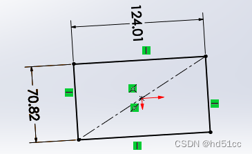
}AddDimension2
        private void SW_Clear(object sender, RoutedEventArgs e)
        {
            //需要打开草图管理器,选定需要标注的对象
            ModelDoc2 model = ((ModelDoc2)(sld4Handler.SwApp.ActiveDoc));
            model.AddDimension2(0,0,0);
        }
AddHorizontalDimension2
        private void SW_Clear(object sender, RoutedEventArgs e)
        {
            //需要打开草图管理器,选定需要标注的对象
            ModelDoc2 model = ((ModelDoc2)(sld4Handler.SwApp.ActiveDoc));
            model.AddHorizontalDimension2(0,0,0);
        }
AlignParallelDimensions
        private void SW_Clear(object sender, RoutedEventArgs e)
        {
            ModelDoc2 model = ((ModelDoc2)(sld4Handler.SwApp.ActiveDoc));
            //先选定尺寸,再执行对其命令
            model.AlignParallelDimensions();
        }
AlignOrdinate
        private void SW_Clear(object sender, RoutedEventArgs e)
        {
            //打开软件,打开文档,鼠标选中纵坐标尺寸组

            ModelDoc2 model = ((ModelDoc2)(sld4Handler.SwApp.ActiveDoc));
            model.AlignOrdinate();
        }
BlankRefGeom
        private void SW_Clear(object sender, RoutedEventArgs e)
        {
            ModelDoc2 model = ((ModelDoc2)(sld4Handler.SwApp.ActiveDoc));
            //先选几何参考,如参考面,再执行对其命令
            model.BlankRefGeom();
        }
BlankSketch
        private void SW_Clear(object sender, RoutedEventArgs e)
        {
            ModelDoc2 model = ((ModelDoc2)(sld4Handler.SwApp.ActiveDoc));
            //先选草图,再执行对其命令
            model.BlankSketch();
        }
BreakDimensionAlignment
        private void SW_Clear(object sender, RoutedEventArgs e)
        {
            ModelDoc2 model = ((ModelDoc2)(sld4Handler.SwApp.ActiveDoc));
            //先选尺寸组,再执行对其命令
            model.BreakDimensionAlignment();
        }
ClearSelection2
        private void SW_Clear(object sender, RoutedEventArgs e)
        {
            ModelDoc2 model = ((ModelDoc2)(sld4Handler.SwApp.ActiveDoc));
            //先选尺寸组,再执行对其命令
            model.ClearSelection2(false);
        }
ClosestDistance
//此示例说明如何计算装配中两个零部件之间的最近距离。

//------------------------------------------------------------
//前提条件:
//1.打开 public_documents\samples\tutorial\api\landing_gear.sldasm。
//2.单击 oleostrut<1> 上的一个面。
//3.Ctrl+单击 lwrsway_lnk<1> 上的一个面。
//4.打开立即窗口。
//
//后置条件:
//1. 使用选择点创建 3D 草图并计算组件之间的距离。
//2.检查立即窗口、图形区域和FeatureManager 设计树。
//注意:因为这个装配体在别处使用,所以不要保存变化。
//------------------------------------------------------------
Option Explicit
Sub main()
    Dim swApp As SldWorks.SldWorks
    Dim swModel As SldWorks.ModelDoc2
    Dim swSelMgr As SldWorks.SelectionMgr
    Dim swFace1 As SldWorks.Face2
    Dim swFace2 As SldWorks.Face2
    Dim vPt1 As Variant
    Dim vPt2 As Variant
    Dim nDist As Double
    Dim swSkPoint1 As SldWorks.SketchPoint
    Dim swSkPoint2 As SldWorks.SketchPoint
    Dim swSkLine As SldWorks.SketchLine
    Dim bRet As Boolean

    Set swApp = Application.SldWorks
    Set swModel = swApp.ActiveDoc
    Set swSelMgr = swModel.SelectionManager
    Set swFace1 = swSelMgr.GetSelectedObject6(1, -1)
    Set swFace2 = swSelMgr.GetSelectedObject6(2, -1)
    nDist = swModel.ClosestDistance(swFace1, swFace2, vPt1, vPt2)
    Debug.Assert nDist > 0#
    Debug.Assert Not IsEmpty(vPt1)
    Debug.Assert Not IsEmpty(vPt2)
    Debug.Print "File = " & swModel.GetPathName
    Debug.Print "  Selection type (swSelFaces = 2)"
    Debug.Print "    1 = " & swSelMgr.GetSelectedObjectType2(1)
    Debug.Print "    2 = " & swSelMgr.GetSelectedObjectType2(2)
    Debug.Print "  Coordinates of selection point"
    Debug.Print "    1 = (" & vPt1(0) * 1000# & ", " & vPt1(1) * 1000# & ", " & vPt1(2) * 1000# & ") mm"
    Debug.Print "    2 = (" & vPt2(0) * 1000# & ", " & vPt2(1) * 1000# & ", " & vPt2(2) * 1000# & ") mm"
    Debug.Print "  Distance between selection points = " & nDist * 1000# & " mm"
    swModel.SetAddToDB True
    swModel.Insert3DSketch2 False
    Set swSkPoint1 = swModel.CreatePoint2(vPt1(0), vPt1(1), vPt1(2))
    Set swSkPoint2 = swModel.CreatePoint2(vPt2(0), vPt2(1), vPt2(2))
    Set swSkLine = swModel.CreateLine2(vPt1(0), vPt1(1), vPt1(2), vPt2(0), vPt2(1), vPt2(2))
    swModel.SetAddToDB False
    swModel.Insert3DSketch2 True
End Sub
CreateArcByCenter
        private void SW_Clear(object sender, RoutedEventArgs e)
        {
            ModelDoc2 model = ((ModelDoc2)(sld4Handler.SwApp.ActiveDoc));
            //单位是米
            model.CreateArcByCenter(0,0,0,0.05,0,0,0,0.05,0);
        }
DeriveSketch
        private void SW_Clear(object sender, RoutedEventArgs e)
        {
            ModelDoc2 model = ((ModelDoc2)(sld4Handler.SwApp.ActiveDoc));
            model.DeriveSketch();
        }
EditConfiguration3
        private void SW_Clear(object sender, RoutedEventArgs e)
        {
            ModelDoc2 model = ((ModelDoc2)(sld4Handler.SwApp.ActiveDoc));
            model.EditConfiguration3("NewCfgName", "NewCfgName2","","",(int)swConfigurationOptions2_e.swConfigOption_DontActivate);
        }
GetAngularUnits
[ AngleUnit, FractionBase, FractionValue, SignificantDigits, RoundToFraction ]
        private void SW_Clear(object sender, RoutedEventArgs e)
        {
            ModelDoc2 model = ((ModelDoc2)(sld4Handler.SwApp.ActiveDoc));
            object data= model.GetAngularUnits();
            short[] datas = (short[])data;
            string s = "";
            s = "AngleUnit:" + ((swAngleUnit_e)datas[0]).ToString() + "\n" + "SignificantDigits :" + datas[3] + "\n";
            MessageBox.Show(s);
        }
GetConfigurationByName
        private void SW_Clear(object sender, RoutedEventArgs e)
        {
            ModelDoc2 model = ((ModelDoc2)(sld4Handler.SwApp.ActiveDoc));
            Configuration configuration = model.GetConfigurationByName("NewCfgName2");
            MessageBox.Show(configuration.Comment);
        }
GetConfigurationCount
        private void SW_Clear(object sender, RoutedEventArgs e)
        {
            ModelDoc2 model = ((ModelDoc2)(sld4Handler.SwApp.ActiveDoc));
            MessageBox.Show(model.GetConfigurationCount().ToString());
        }
GetConfigurationNames
        private void SW_Clear(object sender, RoutedEventArgs e)
        {
            ModelDoc2 model = ((ModelDoc2)(sld4Handler.SwApp.ActiveDoc));
            string[] names = (string[])model.GetConfigurationNames();
            string s = "";
            for (int i = 0; i < names.Length; i++)
            {
                s += names[i] + "\n";
            }
            MessageBox.Show(s);
        }
GetDesignTable
This example shows how to get a design table and its contents.

//---------------------------------------
// Preconditions:
// 1. Open a part or assembly document that
//    contains a design table.
// 2. Verify that a design table exists by
//    expanding Tables in the ConfigurationManager.
// 3. Open the Immediate window.
//
// Postconditions:
// 1. Prints the design table contents to the
//    Immediate window.
// 2. Examine the Immediate window.
//----------------------------------------
using SolidWorks.Interop.sldworks;
using SolidWorks.Interop.swconst;
using System.Runtime.InteropServices;
using System;
using System.Diagnostics;

namespace GetTitleDesignTableCSharp.csproj
{

    partial class SolidWorksMacro
    {

        public void Main()
        {
            ModelDoc2 swModel = default(ModelDoc2);
            DesignTable swDesTable = default(DesignTable);
            int nTotRow = 0;
            int nTotCol = 0;
            string sRowStr = null;
            int i = 0;
            int j = 0;
            bool bRet = false;

            swModel = (ModelDoc2)swApp.ActiveDoc;

            swDesTable = (DesignTable)swModel.GetDesignTable();
            bRet = swDesTable.Attach();

            nTotRow = swDesTable.GetTotalRowCount();
            nTotCol = swDesTable.GetTotalColumnCount();
            Debug.Print("File = " + swModel.GetPathName());
            Debug.Print("  Title        = " + swDesTable.GetTitle());
            Debug.Print("  Row          = " + swDesTable.GetRowCount());
            Debug.Print("  Col          = " + swDesTable.GetColumnCount());
            Debug.Print("  TotRow       = " + nTotRow);
            Debug.Print("  TotCol       = " + nTotCol);
            Debug.Print("  VisRow       = " + swDesTable.GetVisibleRowCount());
            Debug.Print("  VisCol       = " + swDesTable.GetVisibleColumnCount());
            Debug.Print("");

            for (i = 0; i <= nTotRow; i++)
            {
                sRowStr = "  |";
                for (j = 0; j <= nTotCol; j++)
                {
                    sRowStr = sRowStr + swDesTable.GetEntryText(i, j) + "|";
                }
                Debug.Print(sRowStr);
            }
            swDesTable.Detach();
        }

        /// <summary>
        /// The SldWorks swApp variable is pre-assigned for you.
        /// </summary>

        public SldWorks swApp;

    }
}
GetEntityName
Option Explicit
Dim swApp As SldWorks.SldWorks
Dim swSelMgr As SldWorks.SelectionMgr
Dim swModel As SldWorks.ModelDoc2
Dim swComp As SldWorks.Component2
Dim swFace As SldWorks.Face2
Dim boolstatus As Long
Public Sub SelectComponentFaceByName(faceName As String)
    Dim swBody As SldWorks.Body2
    Dim swSelData As SldWorks.SelectData
    Dim currentFaceName As String
    Set swSelData = swSelMgr.CreateSelectData
    ' Get the component body
    Set swBody = swComp.GetBody()
    If (swBody Is Nothing) Then
        swApp.SendMsgToUser "Component body unavailable."
        swApp.SendMsgToUser "Make sure component is not lightweight or suppressed."
        Exit Sub
    End If
    Debug.Print "Traversing faces on component's body..."
    Set swFace = swBody.GetFirstFace
    Do While Not swFace Is Nothing
        currentFaceName = swModel.GetEntityName(swFace)
        If (currentFaceName = faceName) Then
            ' Select the face
            swFace.Select4 False, swSelData
            Debug.Print "  Name of currently selected face; should match name of previously selected face: " & currentFaceName
            Exit Do
        End If
    Set swFace = swFace.GetNextFace
Loop
' Subsequent code might select a second face,
' edge, or feature, and then mate the two
' items using AssemblyDoc::AddMate5
End Sub
Sub main()
    Dim swModelDocExt As SldWorks.ModelDocExtension
    Dim componentName As String
    Dim faceName As String
   Set swApp = CreateObject("SldWorks.Application")
    ' Get active assembly document
    Set swModel = swApp.ActiveDoc()
    Set swModelDocExt = swModel.Extension
    Set swSelMgr = swModel.SelectionManager
    ' Select a component and get its name
    boolstatus = swModelDocExt.SelectByID2("USB_connector_shell2-1@usb_flash_drive2", "COMPONENT", 0, 0, 0, False, 0, Nothing, 0)
    Set swComp = swSelMgr.GetSelectedObject6(1, -1)
    componentName = swComp.Name2
    Debug.Print "Name of selected component: " & componentName
    swModel.ClearSelection2 True
    ' Select a face on the component and
    ' name it
    boolstatus = swModelDocExt.SelectByID2("", "FACE", -6.97433509299117E-03, 8.5197071911125E-04, 5.99999999997181E-03, False, 0, Nothing, 0)
    Set swFace = swSelMgr.GetSelectedObject6(1, -1)
    boolstatus = swModel.SelectedFaceProperties(0, 0, 0, 0, 0, 0, 0, True, "SideFace")
    faceName = swModel.GetEntityName(swFace)
    Debug.Print "Name of selected face on selected component: " & faceName
    SelectComponentFaceByName faceName
End Sub
GetFeatureCount
        private void SW_Clear(object sender, RoutedEventArgs e)
        {
            ModelDoc2 model = ((ModelDoc2)(sld4Handler.SwApp.ActiveDoc));
            int  featCount = model.GetFeatureCount();
            int i;
            Feature theFeature;
            string featName;
            for (i = featCount; i >= 1; i += -1)
            {
                theFeature = (Feature)model.FeatureByPositionReverse(featCount - i);
                if ((theFeature != null))
                {
                    featName = theFeature.Name;
                    MessageBox.Show("Feature " + i.ToString() + " is " + featName);
                }
            }
        }
GetFeatureManagerWidth
        private void SW_Clear(object sender, RoutedEventArgs e)
        {
            ModelDoc2 model = ((ModelDoc2)(sld4Handler.SwApp.ActiveDoc));
            MessageBox.Show(model.GetFeatureManagerWidth().ToString());
        }
GetLines
[ LineType, StartPtX, StartPtY, StartPtZ, EndPtX, EndPtY, EndPtZ, ... ]
GetModelViewNames
Option Explicit

Sub main()

    Dim swApp                   As SldWorks.SldWorks
    Dim swModel                 As SldWorks.ModelDoc2
    Dim vModelViewNames         As Variant
    Dim i                       As Long

    Set swApp = CreateObject("SldWorks.Application")
    Set swModel = swApp.ActiveDoc
    vModelViewNames = swModel.GetModelViewNames
    Debug.Print "FileName = " & swModel.GetPathName
    Debug.Print "  ModelViewCount = " & swModel.GetModelViewCount
    For i = 0 To UBound(vModelViewNames)
        Debug.Print "    " + vModelViewNames(i)
    Next i
End Sub
GetTitle
        private void SW_Clear(object sender, RoutedEventArgs e)
        {
            ModelDoc2 model = ((ModelDoc2)(sld4Handler.SwApp.ActiveDoc));
            MessageBox.Show(model.GetTitle().ToString());
        }
GetType
        private void SW_Clear(object sender, RoutedEventArgs e)
        {
            ModelDoc2 model = ((ModelDoc2)(sld4Handler.SwApp.ActiveDoc));
            MessageBox.Show(((swDocumentTypes_e)model.GetType()).ToString());
        }
GetUnits
        private void SW_Clear(object sender, RoutedEventArgs e)
        {
            ModelDoc2 model = ((ModelDoc2)(sld4Handler.SwApp.ActiveDoc));
            object data= model.GetUnits();//5个参数:长度单位、小数部分(模型单位设置为英寸 swINCHES 或 英尺swFEETINCHES 时有效)、分母值(如果使用小数)、有效数字、四舍五入
            short[] datas = (short[])data;
            string s = "";
            s = "LengthUnit :" + ((swAngleUnit_e)datas[0]).ToString() + "\n" + "FractionBase  :" + ((swFractionDisplay_e)datas[1]).ToString() + "\n" + "FractionValue   :" + datas[2].ToString() + "\n" + "SignificantDigits    :" + datas[3].ToString() + "\n" + "RoundToFraction     :" + datas[4].ToString() + "\n";
            MessageBox.Show(s);
        }
GetUserUnit
        private void SW_Clear(object sender, RoutedEventArgs e)
        {
            ModelDoc2 model = ((ModelDoc2)(sld4Handler.SwApp.ActiveDoc));
            object data= model.GetUserUnit((int)swUserUnitsType_e.swLengthUnit);
            IUserUnit userUnit = (IUserUnit)data;
            MessageBox.Show(((swUserUnitsType_e)userUnit.UnitType).ToString() + "\n" + userUnit.GetUnitsString(true)); ;
        }
InsertCurveFileBegin
//---------------------------------------------------------------------
// Preconditions:
// 1. Verify that the specified part template exists.
// 2. Create c:\temp, if this folder does not exist.
// 3. Open the Immediate window.
//
// Postconditions:
// 1. Creates a new part document.
// 2. Inserts a free point curve feature.
// 3. Gets some free point curve feature data.
// 4. Saves the free point curve feature's points to a file.
// 5. Examine the graphics area, FeatureManager design tree,
//    Immediate window, and c:\temp.
//---------------------------------------------------------------------
using SolidWorks.Interop.sldworks;
using SolidWorks.Interop.swconst;
using System.Runtime.InteropServices;
using System;
using System.Diagnostics;

namespace FreePointCurveFeatureDataCSharp.csproj
{
    public partial class SolidWorksMacro
    {


        public void Main()
        {
            ModelDoc2 swModel = default(ModelDoc2);
            ModelDocExtension swModelDocExt = default(ModelDocExtension);
            SelectionMgr swSelectionMgr = default(SelectionMgr);
            Feature swFeature = default(Feature);
            FreePointCurveFeatureData swFreePointCurveFeatureData = default(FreePointCurveFeatureData);
            bool status = false;
            int nbrPoints = 0;
            double[] pointArray = null;
            int i = 0;

            //Create new part document
            swModel = (ModelDoc2)swApp.NewDocument("C:\\ProgramData\\SolidWorks\\SolidWorks 2015\\templates\\Part.prtdot", 0, 0, 0);

            //Insert free point curve feature
            swModel.InsertCurveFileBegin();
            status = swModel.InsertCurveFilePoint(0, 0, 0);
            status = swModel.InsertCurveFilePoint(0, 0, 0.0127);
            status = swModel.InsertCurveFilePoint(0, 0, 0.0254);
            status = swModel.InsertCurveFilePoint(0, 0, 0.0381);
            status = swModel.InsertCurveFilePoint(0, 0.0254, 0.0381);
            status = swModel.InsertCurveFilePoint(0, 0.0381, 0.0381);
            status = swModel.InsertCurveFileEnd();

            //Get free point curve feature
            swModelDocExt = (ModelDocExtension)swModel.Extension;
            swSelectionMgr = (SelectionMgr)swModel.SelectionManager;
            status = swModelDocExt.SelectByID2("Curve1", "REFERENCECURVES", 0, 0, 0, false, 0, null, 0);
            swFeature = (Feature)swSelectionMgr.GetSelectedObject6(1, -1);
            //Get number of points in free point curve feature
            swFreePointCurveFeatureData = (FreePointCurveFeatureData)swFeature.GetDefinition();
            nbrPoints = swFreePointCurveFeatureData.GetPointCount();
            Debug.Print("Number of points in free point curve feature: " + nbrPoints);
            //Get the points in free point curve feature
            pointArray = (double[])swFreePointCurveFeatureData.PointArray;
            Debug.Print("Points in free point curve feature: ");
            for (i = 0; i <= nbrPoints - 1; i++)
            {
                Debug.Print("  " + pointArray[i]);
            }
            //Save the points in free point curve feature to file
            status = swFreePointCurveFeatureData.SavePointsToFile("c:\\temp\\MyFreePointCurveFeature.sldcrv");
            Debug.Print("Curve file created in specified folder: " + status);

        }

        /// <summary>
        ///  The SldWorks swApp variable is pre-assigned for you.
        /// </summary>
        public SldWorks swApp;
    }
}
InsertDatumTag2
//-----------------------------------------------------------------------------
// Preconditions: Verify that the specified path and template file exist.
//
// Postconditions:
// 1. Creates a part with annotations.
// 2. Click Save.
// 3. Creates a drawing with third-angle views of the part
//    and annotations.
// 4. Iterates through each annotation array and pops up message boxes
//    containing information about each annotation in the drawing views.
// 5. Click OK to close each message box.
//---------------------------------------------------------------------------
using SolidWorks.Interop.sldworks;
using SolidWorks.Interop.swconst;
using System;
namespace GetAnnotationsArrays.csproj
{
    partial class SolidWorksMacro
    {
        const string filedir = "C:\\ProgramData\\SOLIDWORKS\\SOLIDWORKS 2016\\templates\\";
        const string TemplateName = "C:\\ProgramData\\SOLIDWORKS\\SOLIDWORKS 2016\\templates\\drawing.drwdot";
        const int TemplateSize = (int)swDwgTemplates_e.swDwgTemplateBsize;
        const int PaperSize = (int)swDwgPaperSizes_e.swDwgPaperBsize;
        const double ScaleNum = 1.0;
        const double ScaleDenom = 2.0;
        ModelDoc2 swModel;
        FeatureManager swFeatMgr;
        DrawingDoc swDraw;
        Sheet swSheet;
        long j;
        bool retval;
        View swView;
        long count;
        string msg;

        public void Main()
        {
            // Create a part
            Build_Part();

            // Create a drawing of the part
            swModel = (ModelDoc2)swApp.ActiveDoc;
            swDraw = (DrawingDoc)swApp.NewDocument(TemplateName, PaperSize, 0.0, 0.0);
            swDraw.ActivateSheet("Sheet1");
            swSheet = (Sheet)swDraw.GetCurrentSheet();
            swSheet.SetSize(PaperSize, 0.0, 0.0);
            swSheet.SetScale(ScaleNum, ScaleDenom, true, true);

            // Create 3rd-angle drawing views
            // Pop up Save As dialog
            // Click Save in the dialog
            retval = swDraw.Create3rdAngleViews2(swModel.GetPathName());
            double LocX = 0;
            double LocY = 0;
            LocX = 0.2635088599471;
            LocY = 0.1934578136726;
            // Create isometric drawing view
            swDraw.CreateDrawViewFromModelView3(swModel.GetPathName(), "*Isometric", LocX, LocY, 0);
            swDraw.ViewDisplayShaded();
            // Insert display dimension annotations from the current model
            swDraw.InsertModelAnnotations3(0, (int)swInsertAnnotation_e.swInsertDimensionsMarkedForDrawing, true, true, false, true);
            // Insert datum target symbol annotations from the current model
            swDraw.InsertModelAnnotations3(0, (int)swInsertAnnotation_e.swInsertDatumTargets, true, true, false, true);
            // Insert geometric tolerance annotations from the current model
            swDraw.InsertModelAnnotations3(0, (int)swInsertAnnotation_e.swInsertGTols, true, true, false, true);
            // Insert surface finish symbol annotations from the current model
            swDraw.InsertModelAnnotations3(0, (int)swInsertAnnotation_e.swInsertSFSymbols, true, true, false, true);
            // Insert datum tag annotations from the current model
            swDraw.InsertModelAnnotations3(0, (int)swInsertAnnotation_e.swInsertDatums, true, true, false, true);
            // Insert dowel symbol on a selected arc or circle - not applicable to this model
            //swDraw.InsertDowelSymbol
            // Insert center line on a selected entity
            //swDraw.InsertCenterLine2
            // Insert cosmetic thread
            //swDraw.InsertThreadCallout
            // Insert weld symbol on the last edge selection
            //swDraw.InsertWeldSymbol
            // Insert weld bead
            // Insert table
            //swDraw.InsertTableAnnotation2

            swDraw.ForceRebuild();

            // Iterate through all the views on the drawing to find display dimensions
            swView = (View)swDraw.GetFirstView();
            while ((swView != null))
            {
                count = swView.GetDisplayDimensionCount();
                DisplayDimension DisplayDimension = default(DisplayDimension);
                Dimension swDim = default(Dimension);
                // Iterate through all the display dimension annotations in each drawing view that has them
                if (count > 0)
                {
                    Object[] Annotations = (Object[])swView.GetDisplayDimensions();
                    for (j = 0; j <= Annotations.GetUpperBound(0); j++)
                    {
                        DisplayDimension = (DisplayDimension)Annotations[j];
                        swDim = (Dimension)DisplayDimension.GetDimension();
                        // For each annotation in each drawing view, pop up a message box with the
                        // annotation name and corresponding dimension
                        msg = "Display dimension found: " + swView.GetName2() + ":" + ((Annotation)DisplayDimension.GetAnnotation()).GetName() + " = " + swDim.GetSystemValue2("") + " meters";
                        swApp.SendMsgToUser2(msg, (int)swMessageBoxIcon_e.swMbInformation, (int)swMessageBoxBtn_e.swMbOk);
                    }
                }
                swView = (View)swView.GetNextView();
            }
            // Iterate through all the views on the drawing to find datum target symbols
            swView = (View)swDraw.GetFirstView();
            while ((swView != null))
            {
                count = swView.GetDatumTargetSymCount();
                DatumTargetSym dtsymbol = default(DatumTargetSym);
                // Iterate through all the datum target symbol annotations in each drawing view that has them
                if (count > 0)
                {
                    Object[] Annotations = (Object[])swView.GetDatumTargetSyms();
                    for (j = 0; j <= Annotations.GetUpperBound(0); j++)
                    {
                        dtsymbol = (DatumTargetSym)Annotations[j];
                        // For each annotation in each drawing view, pop up a message box with the
                        // annotation name and name of each datum target symbol found
                        msg = "Datum target symbol found: " + swView.GetName2() + ":" + ((Annotation)dtsymbol.GetAnnotation()).GetName();
                        swApp.SendMsgToUser2(msg, (int)swMessageBoxIcon_e.swMbInformation, (int)swMessageBoxBtn_e.swMbOk);
                    }
                }
                swView = (View)swView.GetNextView();
            }
            // Iterate through all the views on the drawing to find surface finish symbols
            swView = (View)swDraw.GetFirstView();
            while ((swView != null))
            {
                count = swView.GetSFSymbolCount();
                SFSymbol sfsymbol = default(SFSymbol);
                // Iterate through all the surface finish symbol annotations in each drawing view that has them
                if (count > 0)
                {
                    Object[] Annotations = (Object[])swView.GetSFSymbols();
                    for (j = 0; j <= Annotations.GetUpperBound(0); j++)
                    {
                        sfsymbol = (SFSymbol)Annotations[j];
                        // For each annotation in each drawing view, pop up a message box with the
                        // annotation name and name of each surface finish symbol found
                        msg = "Surface finish symbol found: " + swView.GetName2() + ":" + ((Annotation)sfsymbol.GetAnnotation()).GetName();
                        swApp.SendMsgToUser2(msg, (int)swMessageBoxIcon_e.swMbInformation, (int)swMessageBoxBtn_e.swMbOk);
                    }
                }
                swView = (View)swView.GetNextView();
            }
            // Iterate through all the views on the drawing to find datum tags
            swView = (View)swDraw.GetFirstView();
            while ((swView != null))
            {
                count = (int)swView.GetDatumTagCount();
                DatumTag dTag = default(DatumTag);
                // Iterate through all the datum tags in each drawing view that has them
                if (count > 0)
                {
                    Object[] Annotations = (Object[])swView.GetDatumTags();
                    for (j = 0; j <= Annotations.GetUpperBound(0); j++)
                    {
                        dTag = (DatumTag)Annotations[j];
                        // For each annotation in each drawing view, pop up a message box with the
                        // annotation name and name of each datum tag found
                        msg = "Datum tag found: " + swView.GetName2() + ":" + ((Annotation)dTag.GetAnnotation()).GetName();
                        swApp.SendMsgToUser2(msg, (int)swMessageBoxIcon_e.swMbInformation, (int)swMessageBoxBtn_e.swMbOk);
                    }
                }
                swView = (View)swView.GetNextView();
            }
            // Iterate through all the views on the drawing to find geometric tolerances
            swView = (View)swDraw.GetFirstView();
            while ((swView != null))
            {
                count = (int)swView.GetGTolCount();
                Gtol gtol = default(Gtol);
                // Iterate through all the geometric tolerance symbols in each drawing view that has them
                if (count > 0)
                {
                    Object[] Annotations = (Object[])swView.GetGTols();
                    for (j = 0; j <= Annotations.GetUpperBound(0); j++)
                    {
                        gtol = (Gtol)Annotations[j];
                        // For each annotation in each drawing view, pop up a message box with the
                        // annotation name and name of each geometric tolerance found
                        msg = "Geometric tolerance symbol found: " + swView.GetName2() + ":" + ((Annotation)gtol.GetAnnotation()).GetName();
                        swApp.SendMsgToUser2(msg, (int)swMessageBoxIcon_e.swMbInformation, (int)swMessageBoxBtn_e.swMbOk);
                    }
                }
                swView = (View)swView.GetNextView();
            }
            // In a similar fashion:
            // Get other annotations on the drawing, if they exist
            // Iterate through all the views on the drawing
            // Get the annotation count, and if greater than zero, get the annotation array
            // Iterate on each array, and Set an annotation object to each array member:
            // Annotations = swView.GetDowelSymbols
            // Annotations = swView.GetMultiJogLeaders
            // Annotations = swView.GetDatumOrigins
            // Annotations = swView.GetCenterLines
            // Annotations = swView.GetCThreads
            // Annotations = swView.GetWeldSymbols
            // Annotations = swView.GetWeldBeads
            // Annotations = swView.GetTableAnnotations

            swApp.SetUserPreferenceToggle((int)swUserPreferenceToggle_e.swInputDimValOnCreate, true);
            swModel.SetUserPreferenceToggle((int)swUserPreferenceToggle_e.swDisplayAnnotations, false);
        }
        private void Build_Part()
        {
            // Builds a part with these annotations:
            // display dimensions, geometric tolerance symbol,
            // surface finish symbol, datum tag symbol, and datum target symbol
            swModel = (ModelDoc2)swApp.NewDocument(filedir + "part.prtdot", 0, 0.0, 0.0);
            swModel.SetUserPreferenceIntegerValue((int)swUserPreferenceIntegerValue_e.swUnitsLinear, (int)swLengthUnit_e.swMETER);
            swModel.SetUserPreferenceDoubleValue((int)swUserPreferenceDoubleValue_e.swMaterialPropertyDensity, 7800);
            swModel.SetUserPreferenceStringValue((int)swUserPreferenceStringValue_e.swMaterialPropertyCrosshatchPattern, "ISO (Steel)");
            swModel.SketchManager.InsertSketch(false);
            double Height = 0;
            double Width = 0;
            Height = 0.05;
            Width = 0.05;
            swApp.SetUserPreferenceToggle((int)swUserPreferenceToggle_e.swInputDimValOnCreate, false);
            swModel.SketchManager.CreateLine(0.01, 0.01, 0, 0.01, 0.01 + Height, 0);
            swModel.ViewZoomtofit2();
            // Add display dimension to line
            swModel.AddDimension2(0, 0.01 + Height / 2, 0);
            // Add geometric tolerance to line
            swModel.InsertGtol();
            swModel.SketchManager.CreateLine(0.01, 0.01, 0, 0.01 + Width, 0.01, 0);
            swModel.ViewZoomtofit2();
            // Add display dimension
            swModel.AddDimension2(0.01 + Width / 2, 0, 0);
            // Add surface finish symbol to line
            swModel.Extension.InsertSurfaceFinishSymbol3((int)swSFSymType_e.swSFBasic, (int)swLeaderStyle_e.swSTRAIGHT, 0.01, 0.01, 0.01, (int)swSFLaySym_e.swSFCircular, (int)swArrowStyle_e.swDOT_ARROWHEAD, "", "", "",
            "", "", "", "");
            swModel.SketchManager.CreateLine(0, 0, 0, 0, 0.01, 0).ConstructionGeometry = true;
            swModel.ClearSelection2(true);
            swModel.ViewZoomtofit2();
            double Thick = 0;
            Thick = 0.05;
            double Depth = 0;
            Depth = 0.05;
            swFeatMgr = swModel.FeatureManager;
            swFeatMgr.FeatureExtrusionThin2(true, false, true, 0, 0, Depth, 0, false, false, false,
            false, 0, 0, false, false, false, false, false, Thick, 0,
            0, 0, 0, false, 0.0, false, false, (int)swStartConditions_e.swStartSketchPlane, 0.0, false
            );
            swModel.ViewZoomtofit2();
            swModel.SetUserPreferenceToggle((int)swUserPreferenceToggle_e.swDisplayAnnotations, true);
            swModel.ShowNamedView2("Isometric", 7);
            swModel.ViewZoomtofit2();
            // Add datum tag to line
            retval = swModel.Extension.SelectByID2("", "EDGE", 0.06001738353251, -0.01284975502705, -0.05001738353241, false, 0, null, 0);
            DatumTag dTag = default(DatumTag);
            dTag = (DatumTag)swModel.InsertDatumTag2();
            // Add datum target symbol to line
            retval = swModel.Extension.SelectByID2("", "EDGE", 0.06001738353251, -0.01284975502705, -0.05001738353241, false, 0, null, 0);
            object myDatumTarget = null;
            myDatumTarget = swModel.Extension.InsertDatumTargetSymbol2("", "", "", 0, false, 0.03, 0.03, "", "", true,
            12, 0, false, true, true);

        }

        /// <summary>
        /// The SldWorks swApp variable is pre-assigned for you.
        /// </summary>
        public SldWorks swApp;

    }
}
InsertDome
//---------------------------------------------------------
// Preconditions:
// 1. Verify that the part document to open exists.
// 2. Open the Immediate window.
//
// Postconditions:
// 1. Opens the specified part document.
// 2. Edits Sketch1, sketches an ellipse, and creates a boss feature.
// 3. Selects a face on the boss feature and
//    inserts a dome feature.
// 4. Prints to the Immediate window some
//    dome feature data.
// 5. Reverses the direction of the dome feature.
// 6. Examine the Immediate window, graphics area,
//    and FeatureManager design tree.
//
// NOTE: Because the part is used elsewhere, do not
// save changes.
//----------------------------------------------------------
using SolidWorks.Interop.sldworks;
using SolidWorks.Interop.swconst;
using System.Runtime.InteropServices;
using System;
using System.Diagnostics;

namespace DomeFeatureData2CSharp.csproj
{
    public partial class SolidWorksMacro
    {
        public void Main()
        {
            ModelDoc2 swModel = default(ModelDoc2);
            ModelDocExtension swModelDocExt = default(ModelDocExtension);
            SketchManager swSketchMgr = default(SketchManager);
            SketchSegment swSketchSegment = default(SketchSegment);
            Feature swFeature = default(Feature);
            SelectionMgr swSelectionMgr = default(SelectionMgr);
            DomeFeatureData2 swDomeFeatureData = default(DomeFeatureData2);
            object[] faces = null;
            Face2 swFace = default(Face2);
            Body2 oneBody = default(Body2);
            string fileName = null;
            bool status = false;
            int errors = 0;
            int warnings = 0;

            //Open model document to which to add a dome feature
            fileName = "C:\\Users\\Public\\Documents\\SOLIDWORKS\\SOLIDWORKS 2018\\samples\\tutorial\\api\\box.sldprt";
            swModel = (ModelDoc2)swApp.OpenDoc6(fileName, (int)swDocumentTypes_e.swDocPART, (int)swOpenDocOptions_e.swOpenDocOptions_Silent, "", ref errors, ref warnings);

            //Open sketch to which to add a sketch of an ellipse
            swModelDocExt = (ModelDocExtension)swModel.Extension;
            status = swModelDocExt.SelectByID2("Sketch1", "SKETCH", 0, 0, 0, false, 0, null, 0);
            swModel.EditSketch();
            swModel.ClearSelection2(true);

            //Sketch an ellipse
            swModel.ShowNamedView2("*Top", 5);
            swSketchMgr = (SketchManager)swModel.SketchManager;
            swSketchSegment = (SketchSegment)swSketchMgr.CreateEllipse(-0.0761501034873036, 0.0490523248480422, 0, -0.0513492425103863, 0.0490523248480422, 0, -0.0761501034873036, 0.0545451329838695, 0);
            swModel.ClearSelection2(true);
            swSketchMgr.InsertSketch(true);
            swModel.ViewZoomtofit2();
            swModel.ShowNamedView2("*Dimetric", 9);

            //Insert dome feature
            status = swModelDocExt.SelectByID2("", "FACE", -0.0930732824141103, 0.0299999999999727, -0.0482299571224303, true, 0, null, 0);
            swModel.ClearSelection2(true);
            status = swModelDocExt.SelectByID2("", "FACE", -0.0930732824141103, 0.0299999999999727, -0.0482299571224303, false, 1, null, 0);
            swModel.InsertDome(0.01, false, true);

            //Get and modify dome feature data
            status = swModelDocExt.SelectByID2("Dome1", "BODYFEATURE", 0, 0, 0, false, 0, null, 0);
            swSelectionMgr = (SelectionMgr)swModel.SelectionManager;
            swFeature = (Feature)swSelectionMgr.GetSelectedObject6(1, -1);
            swDomeFeatureData = (DomeFeatureData2)swFeature.GetDefinition();
            status = swDomeFeatureData.AccessSelections(swModel, null);
            Debug.Print("Is dome feature elliptical? " + swDomeFeatureData.Elliptical);
            Debug.Print("Height of dome: " + swDomeFeatureData.Height);
            Debug.Print("Number of faces on dome feature: " + swDomeFeatureData.GetFaceCount());
            faces = (object[])swDomeFeatureData.Faces;
            foreach (object aFace in faces)
            {
                swFace = (Face2)aFace;
                oneBody = (Body2)swFace.GetBody();
                Debug.Print("Name of body for this dome feature face: " + oneBody.Name);
            }
            //Change direction of dome feature to concave
            swDomeFeatureData.ReverseDir = true;
            status = swFeature.ModifyDefinition(swDomeFeatureData, swModel, null);

        }

        /// <summary>
        ///  The SldWorks swApp variable is pre-assigned for you.
        /// </summary>
        public SldWorks swApp;
    }
}
InsertFamilyTableEdit
        private void SW_Clear(object sender, RoutedEventArgs e)
        {
            ModelDoc2 model = ((ModelDoc2)(sld4Handler.SwApp.ActiveDoc));
            model.InsertFamilyTableEdit();
        }
InsertFamilyTableNew
        private void SW_Clear(object sender, RoutedEventArgs e)
        {
            ModelDoc2 model = ((ModelDoc2)(sld4Handler.SwApp.ActiveDoc));
            model.InsertFamilyTableNew();
        }
InsertFamilyTableOpen
        private void SW_Clear(object sender, RoutedEventArgs e)
        {
            ModelDoc2 model = ((ModelDoc2)(sld4Handler.SwApp.ActiveDoc));
            model.InsertFamilyTableOpen(@"G:\标准件(20210908)\Part1.xlsx");
        }
InsertHelix
//This example shows how to create a spiral.

//----------------------------------------------------------
// Preconditions: Specified part template exists.
//
// Postconditions:
// 1. Opens a new part.
// 2. Selects Front Plane on which to create a circle.
// 3. Creates a circle.
// 4. Creates a spiral using the circle.
//----------------------------------------------------------
using SolidWorks.Interop.sldworks;
using SolidWorks.Interop.swconst;
using System.Runtime.InteropServices;
using System;
using System.Diagnostics;

namespace SpiralCSharp.csproj
{
    public partial class SolidWorksMacro
    {


        public void Main()
        {
            ModelDoc2 swModel = default(ModelDoc2);
            ModelDocExtension swModelDocExt = default(ModelDocExtension);
            SketchManager swSketchMgr = default(SketchManager);
            SketchSegment swSketchSegment = default(SketchSegment);
            bool status = false;

            swModel = (ModelDoc2)swApp.NewDocument("C:\\ProgramData\\SOLIDWORKS\\SOLIDWORKS 2015\\templates\\Part.prtdot", 0, 0, 0);
            //Select Front Plane, create circle, and create
            //spiral using circle
            swModelDocExt = (ModelDocExtension)swModel.Extension;
            status = swModelDocExt.SelectByID2("Front Plane", "PLANE", -0.0517981810568133, 0.0505753331558577, 0.0012310671470727, false, 0, null, 0);
            swModel.ClearSelection2(true);
            swSketchMgr = (SketchManager)swModel.SketchManager;
            swSketchSegment = (SketchSegment)swSketchMgr.CreateCircle(0.0, 0.0, 0.0, 0.021866, 0.001156, 0.0);
            swModel.InsertHelix(false, true, false, false, (int)swHelixDefinedBy_e.swHelixDefinedBySpiral, 0, 0.04, 2, 0, 4.712388980385);


        }

        /// <summary>
        ///  The SldWorks swApp variable is pre-assigned for you.
        /// </summary>
        public SldWorks swApp;
    }
}
SelectedFeatureProperties
This example shows how to create a thicken feature in a multibody part.

'-------------------------------------------------------------------
' Preconditions:
' 1. Open public_documents\samples\tutorial\multibody\multi_local.sldprt.
' 2. Open the Immediate window.
'
' Postconditions:
' 1. Creates an offset plane and offset surface.
' 2. Selects a face on one body and the offset surface.
' 3. Creates a thicken feature.
' 4. Accesses the thicken feature and gets some property values.
' 5. Examine the graphics area and Immediate window.
'
' NOTE: Because the part is used elsewhere, do not save changes.
'-------------------------------------------------------------------
Option Explicit
Dim swApp As SldWorks.SldWorks
Dim swModel As SldWorks.ModelDoc2
Dim swModelDocExt As SldWorks.ModelDocExtension
Dim swSelMgr As SldWorks.SelectionMgr
Dim swRefPlane As SldWorks.RefPlane
Dim swFeatureMgr As SldWorks.FeatureManager
Dim swPlane As SldWorks.RefPlane
Dim swFeatureThicken As SldWorks.Feature
Dim swFeatureThicken_DEF As SldWorks.ThickenFeatureData
Dim status As Boolean
Sub main()
    Set swApp = Application.SldWorks
    Set swModel = swApp.ActiveDoc
    Set swModelDocExt = swModel.Extension
    'Create offset surface
    status = swModelDocExt.SelectByID2("Top", "PLANE", 0, 0, 0, True, 0, Nothing, 0)
    Set swFeatureMgr = swModel.FeatureManager
    Set swRefPlane = swFeatureMgr.InsertRefPlane(264, 0.01, 0, 0, 0, 0)
    swModel.ClearSelection2 True
    status = swModelDocExt.SelectByID2("", "FACE", 2.35573770133328E-02, 0, -2.4476412300487E-03, False, 0, Nothing, 0)
    status = swModelDocExt.SelectByID2("", "FACE", -5.61529049190312E-02, 0, -2.56278005667809E-03, True, 0, Nothing, 0)
    swModel.InsertOffsetSurface 0.01, False
    swModel.ClearSelection2 True
    status = swModelDocExt.SelectByID2("Extrude1", "BODYFEATURE", 0, 0, 0, False, 0, Nothing, 0)
    status = swModelDocExt.SelectByID2("Surface-Offset1[1]", "SURFACEBODY", 3.19724221122328E-02, -9.99999999999091E-03, -1.04277742429417E-02, False, 1, Nothing, 0)
    ' Thicken the selected reference surface and then generate a boss
    Set swFeatureThicken = swFeatureMgr.FeatureBossThicken(0.01, 0, 96, False, True, False, True)
    swModel.ClearSelection2 True
    ' Set the property values for the selected feature
    swModel.SelectedFeatureProperties 0, 0, 0, 0, 0, 0, 0, 1, 0, "Thicken1"

    ' Get the thicken feature definition object
    Set swFeatureThicken_DEF = swFeatureThicken.GetDefinition
    swFeatureThicken_DEF.AccessSelections swModel, Nothing
    ' Display whether a boss feature
    Debug.Print "Boss feature? " & swFeatureThicken_DEF.IsBossFeature
    ' Display whether the results of this thicken feature are merged
    Debug.Print "Merged? " & swFeatureThicken_DEF.Merge
    ' Display whether all or only specific bodies were
    ' automatically selected for the thicken feature
    Debug.Print "All bodies automatically selected? " & swFeatureThicken_DEF.AutoSelect
    swFeatureThicken_DEF.ReleaseSelectionAccess
End Sub
Parameter
//This example shows how to recalculate the bounding box of an assembly.

//-----------------------------------------
// Preconditions:
// 1. Specified assembly document exists.
// 2. Open the Immediate window.
// 3. Run the macro.
//
// Postconditions:
// 1. Opens assembly document.
// 2. Gets the bounding box for the assembly.
// 3. Prints the lower- and upper-diagonal corner points
//    of the bounding box to the Immediate window.
// 4. Modifies a dimension in a component in the assembly.
// 5. Updates the bounding box.
// 6. Prints the lower- and upper-diagonal corner points
//    of the bounding box to the Immediate window.
// 7. Examine the values printed to the Immediate window
//    to verify that the bounding box was updated.
//
// NOTE: Because this assembly is used elsewhere,
// do not save any changes when closing it.
//-------------------------------------------
using SolidWorks.Interop.sldworks;
using SolidWorks.Interop.swconst;
using System.Runtime.InteropServices;
using System;
using System.Diagnostics;

namespace UpdateBoxCSharp.csproj
{
    public partial class SolidWorksMacro
    {

        public void ProcessAssyBox(SldWorks swApp, AssemblyDoc swAssy)
        {
            object box = null;
            double[] boxArray = new double[6];
            box = (object)swAssy.GetBox((int)swBoundingBoxOptions_e.swBoundingBoxIncludeRefPlanes);
            boxArray = (double[])box;
            Debug.Print("  Min = (" + boxArray[0] * 1000.0 + ", " + boxArray[1] * 1000.0 + ", " + boxArray[2] * 1000.0 + ") mm");
            Debug.Print("  Max = (" + boxArray[3] * 1000.0 + ", " + boxArray[4] * 1000.0 + ", " + boxArray[5] * 1000.0 + ") mm");
        }

        public void Main()
        {
            ModelDoc2 swModel;
            AssemblyDoc swAssy;
            ModelDocExtension swModelDocExt;
            Dimension swDimension;//尺寸
            string fileName;
            int errors = 0;
            int warnings = 0;
            bool status;

            fileName = "C:\\Users\\Public\\Documents\\SOLIDWORKS\\SOLIDWORKS 2018\\samples\\tutorial\\api\\key pad_1.sldasm";
            swModel = (ModelDoc2)swApp.OpenDoc6(fileName, (int)swDocumentTypes_e.swDocASSEMBLY, (int)swOpenDocOptions_e.swOpenDocOptions_Silent, "", ref errors, ref warnings);
            swAssy = (AssemblyDoc)swModel;
            swModelDocExt = (ModelDocExtension)swModel.Extension;

            // Print the two diagonal corner points
            // of the bounding box before modifying the
            // assembly
            Debug.Print("Before:");
            ProcessAssyBox(swApp, swAssy);

            // Change a dimension of one of the assembly components
            status = swModelDocExt.SelectByID2("Sketch1@Pad_1-1@key pad_1", "SKETCH", 0, 0, 0, false, 0, null, 0);
            swModel.EditSketch();
            swModel.ClearSelection2(true);
            status = swModelDocExt.SelectByID2("D1@Sketch1@Pad_1-1@key pad_1", "DIMENSION", 0.00306153201295202, 0.0373842545521677, -0.0323079625553351, false, 0, null, 0);
            swModel.ClearSelection2(true);
            swDimension = (Dimension)swModel.Parameter("D1@Sketch1@pad_1.Part");    //读取尺寸
            errors = (int)swDimension.SetSystemValue3(0.04, (int)swSetValueInConfiguration_e.swSetValue_InThisConfiguration, null);
            swModel.ClearSelection2(true);

            // Update the bounding box
            swAssy.UpdateBox();

            // Print the two diagonal corner points of the
            // bounding box after modifying the assembly
            Debug.Print("After:");
            ProcessAssyBox(swApp, swAssy);


        }

        /// <summary>
        ///  The SldWorks swApp variable is pre-assigned for you.
        /// </summary>
        public SldWorks swApp;
    }
}


 被折叠的 条评论
为什么被折叠?
被折叠的 条评论
为什么被折叠?
 到【灌水乐园】发言


