


【1】增加對S3C2440一些寄存器的支持,添加中斷禁止部分和時钟設置部分
用gedit打開cpu/arm920t/start.S,定位到134行附近,如下代碼
#if defined(CONFIG_S3C2400) || defined(CONFIG_S3C2410)
/* turn off the watchdog */
由於2410和2440的寄存器及地址大部分是一致的,所以這裏就直接在2410的基礎上再加上對2440的支持即可,修改後代碼如下:
#if defined(CONFIG_S3C2400) || defined(CONFIG_S3C2410) || defined(CONFIG_S3C2440)
/* turn off the watchdog */
... ...
# if defined(CONFIG_S3C2410)
ldr r1, =0x3ff
ldr r0, =INTSUBMSK
str r1, [r0]
# endif
# if defined(CONFIG_S3C2440)//添加s3c2440的中斷禁止部分
ldr r1, =0x7fff //根據2440芯片手冊,INTSUBMSK寄存器有15位可用
ldr r0, =INTSUBMSK
str r1, [r0]
# endif
# if defined(CONFIG_S3C2440) //添加s3c2440的時钟部分
#define MPLLCON 0x4C000004 //系統主頻配置寄存器基地址
#define UPLLCON 0x4C000008 //USB時钟頻率配置寄存器基地址
ldr r0, =CLKDIVN //設置分頻系數FCLK:HCLK:PCLK = 1:4:8
mov r1, #5
str r1, [r0]
ldr r0, =MPLLCON //設置系統主頻为405MHz
ldr r1, =0x7F021 //這個值参考芯片手冊“PLL VALUE SELECTION TABLE”部分
str r1, [r0]
ldr r0, =UPLLCON //設置USB時钟頻率为48MHz
ldr r1, =0x38022 //這個值参考芯片手冊“PLL VALUE SELECTION TABLE”部分
str r1, [r0]
# else //其他開發板的時钟部分
/* FCLK:HCLK:PCLK = 1:2:4 */
/* default FCLK is 202.8 MHz ! */
ldr r0, =CLKDIVN
mov r1, #3
str r1, [r0]
ldr r0, =MPLLCON //設置系統主頻为202.8MHz(可以先不添加,對我們的移植沒有影響)
ldr r1, =0xa1031 //這個值参考芯片手冊“PLL VALUE SELECTION TABLE”部分(可以先不添加,對我們的移植沒有影響)
str r1, [r0](可以先不添加,對我們的移植沒有影響)
# endif
#endif /* CONFIG_S3C2400 || CONFIG_S3C2410 || CONFIG_S3C2440 */
首先,上面INTSUBMSK寄存器有15位可用與2410是不同的,在之前的文章中已經做出說明了,這裏不在說了,說一下時钟部分:看一下這兩個寄存器
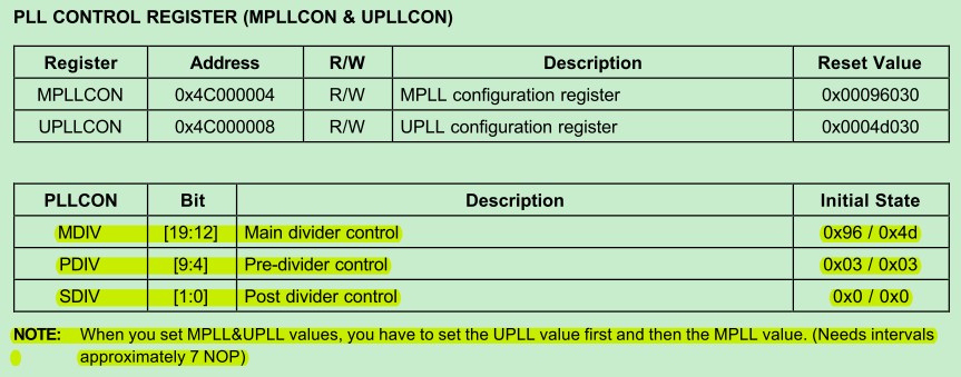
下面的說明也許需要注意一下,手冊中說在設置MPLLCON和UPLLCON時要先設置UPLLCON,之後再設置MPLLCON,上面作者是沒有按照這個要求來做的,沒有去驗證是否對系統有影響,在我的移植過程中我是按照手冊中的要求,按順序設置的,然後怎麼通過設置MPLLCON和UPLLCON獲得我們想要的系統主頻時钟和USB時钟呢,手冊上面给了我們一個計算方法,當然我們一般直接按照手冊中给出的表獲得我們想要的配置
看看這個配置表吧,我們用這個配置表來配置:
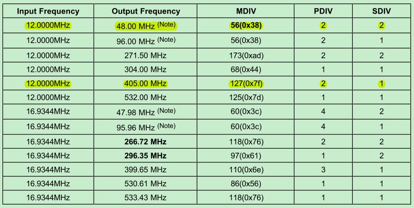
我們把主頻時钟配置为405MHz,那麼按照上面的說明,MDIV=127,PDIV=2,SDIV=1,所以MPLLCON =0x7F021,同理,把USB時钟配置为48MHz,按照上面的說明,MDIV=56,PDIV=2,SDIV=2,所以,UPLLCON=0x38022,設置分頻系數FCLK:HCLK:PCLK = 1:4:8,下面
【2】S3C2440的時钟部分除了在start.S中添加外,還要分別在board/samsung/mini2440/mini2440.c和cpu/arm920t/s3c24x0/speed.c中修改或添加部分代碼。
(1)用gedit打開board/samsung/mini2440/mini2440.c,定位到33行,修改或添加如下內容:
//設置主頻和USB時钟頻率参數與start.S中的一致
#define FCLK_SPEED 2 //設置默認等於2
#if FCLK_SPEED==0 /* Fout = 203MHz, Fin = 12MHz for Audio */
#define M_MDIV 0xC3
#define M_PDIV 0x4
#define M_SDIV 0x1
#elif FCLK_SPEED==1 /* Fout = 202.8MHz */
#define M_MDIV 0xA1
#define M_PDIV 0x3
#define M_SDIV 0x1
#elif FCLK_SPEED==2 /* Fout = 405MHz */
#define M_MDIV 0x7F //這三個值根據S3C2440芯片手冊“PLL VALUE SELECTION TABLE”部分進行設置
#define M_PDIV 0x2
#define M_SDIV 0x1
#endif
#define USB_CLOCK 2 //設置默認等於2
#if USB_CLOCK==0
#define U_M_MDIV 0xA1
#define U_M_PDIV 0x3
#define U_M_SDIV 0x1
#elif USB_CLOCK==1
#define U_M_MDIV 0x48
#define U_M_PDIV 0x3
#define U_M_SDIV 0x2
#elif USB_CLOCK==2 /* Fout = 48MHz */
#define U_M_MDIV 0x38 //這三個值根據S3C2440芯片手冊“PLL VALUE SELECTION TABLE”部分進行設置
#define U_M_PDIV 0x2
#define U_M_SDIV 0x2
#endif
(2)用gedit打開cpu/arm920t/s3c24x0/speed.c,定位到69行加入如下代碼
m = ((r & 0xFF000) >> 12) + 8;
p = ((r & 0x003F0) >> 4) + 2;
s = r & 0x3;
//根據設置的分頻系數FCLK:HCLK:PCLK = 1:4:8修改獲取時钟頻率的函數
#if defined(CONFIG_S3C2440)
if(pllreg == MPLL)//参考S3C2440芯片手冊上的公式:PLL=(2 * m * Fin)/(p * 2s)
return((CONFIG_SYS_CLK_FREQ * m * 2) / (p << s));
//else if (pllreg == UPLL) //warning: control reaches end of non-void function
#endif
return((CONFIG_SYS_CLK_FREQ * m) / (p << s));
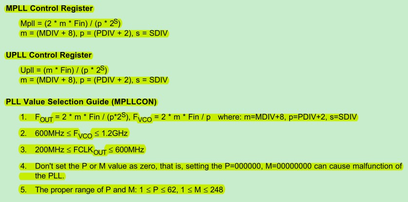
为什麼要再返回時加一個判斷呢?因为在2440中MPLL的時钟为UPLL時钟的2倍,這個地方也是我有疑問的地方,雖然是2倍的關系不錯,我這裏在移植過程中還是加入了UPLL分支的計算方法,在s3c2440的數據手冊裏的227頁這样寫到MPLL和UPLL的計算方法
MPLL Control Register
Mpll = (2 * m * Fin) / (p * 2s)
m = (MDIV + 8), p = (PDIV + 2), s = SDIV
UPLL Control Register
Upll = (m * Fin) / (p * 2s)
m = (MDIV + 8), p = (PDIV + 2), s = SDIV
程序先獲得m,p,s,然後根據這三個變量求出響應的值,這個就是修改此函數的緣由。
由於S3C2410和S3C2440的設置方法也不一样,所以get_HCLK函數也需要修改:
/* return HCLK frequency */
ulong get_HCLK(void)
{
S3C24X0_CLOCK_POWER * const clk_power = S3C24X0_GetBase_CLOCK_POWER();
#if defined(CONFIG_S3C2440)
if (clk_power->CLKDIVN & 0x6)
{
if ((clk_power->CLKDIVN & 0x6)==2) return(get_FCLK()/2);
if ((clk_power->CLKDIVN & 0x6)==6) return((clk_power->CAMDIVN & 0x100) ? get_FCLK()/6 : get_FCLK()/3);
if ((clk_power->CLKDIVN & 0x6)==4) return((clk_power->CAMDIVN & 0x200) ? get_FCLK()/8 : get_FCLK()/4);
return(get_FCLK());(似乎有點多餘)
}
else return(get_FCLK());
#else
return((clk_power->CLKDIVN & 0x2) ? get_FCLK()/2 : get_FCLK());
#endif
}
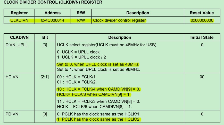
這裏用到了將在include/s3c24x0.h文件裏所添加的CAMDIVN 項,因为這一項的值决定了我們的時钟配置。
這样修改的原因是在s3c2440的數據手冊的231頁有這样一段話:
我們到底應該返回FCLK的幾分之一在這裏就有秒數,其中必須根據HDIVN 的值與CAMDIVN的值來判斷。
【3】加入LED進度指示,增加控制台顯示信息
作用是顯示代碼進度,對 Debug 有幫助。這裏先看一下led的硬件連接

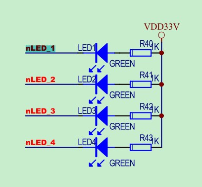
(1)代碼在跳轉到第二階段代碼start_armboot 函數前會亮起一個LED 燈,打開cpu/arm920t/start.S,定位到240行附近,修改如下:
clbss_l: str r2, [r0] /* clear loop... */
add r0, r0, #4
cmp r0, r1
ble clbss_l
#if defined(CONFIG_MINI2440_LED)
//根據mini2440原理圖可知LED分別由S3C2440的PB5、6、7、8口來控制,
//以下是PB端口寄存器基地址(查2440的DataSheet得知)
#define GPBCON 0x56000010
#define GPBDAT 0x56000014
#define GPBUP 0x56000018
//以下對寄存器的操作参照S3C2440的DataSheet進行操作
ldr r0, =GPBUP
ldr r1, =0x7FF //即:二進制11111111111,關閉PB口上拉
str r1, [r0]
ldr r0, =GPBCON //配置PB5、6、7、8为輸出口,對應PBCON寄存器的第10-17位
ldr r1, =0x154FD //即:二進制010101010011111101
str r1, [r0]
ldr r0, =GPBDAT
ldr r1, =0x1C0 //即:二進制111000000,PB5設为低電平,6、7、8为高電平
str r1, [r0]
#endif
//此段代碼使u-boot启動後,開發板上的LED1被點亮,而LED2、LED3、LED4不亮
ldr pc, _start_armboot
_start_armboot: .word start_armboot
#define STACK_BASE 0x33f00000
#define STACK_SIZE 0x10000
.align 2
DW_STACK_START: .word STACK_BASE+STACK_SIZE-4
1.首先通過GPBUP關閉GPB口上拉

所以設置GPBUP=0x7FF
2.配置GPB5,6,7,8为輸出
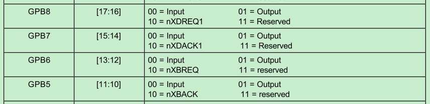
作者使用設置GPBCON=0x154FD,其中GPB1234全部reserved,GPB0同样設为輸出,查看原理圖可以知道,GPB0連接蜂鳴器,使蜂鳴器可以鳴叫
3.是第一個燈亮,就不解釋了,懶得解釋了
(2)在完成board_init函數初始化時的點亮第二個LED,修改如下:
打開board/samsung/mini2440/mini2440.c,定位到100行附近,修改如下:
/* set up the I/O ports */
gpio->GPACON = 0x007FFFFF;
#if defined(CONFIG_MINI2440)
gpio->GPBCON = 0x00295551;
#else
gpio->GPBCON = 0x00044556;
#endif
gpio->GPBUP = 0x000007FF;
gpio->GPCCON = 0xAAAAAAAA;
gpio->GPCUP = 0xFFFFFFFF;
gpio->GPDCON = 0xAAAAAAAA;
gpio->GPDUP = 0xFFFFFFFF;
gpio->GPECON = 0xAAAAAAAA;
gpio->GPEUP = 0x0000FFFF;
gpio->GPFCON = 0x000055AA;
gpio->GPFUP = 0x000000FF;
gpio->GPGCON = 0xFF95FFBA;
gpio->GPGUP = 0x0000FFFF;
gpio->GPHCON = 0x0016FAAA;
gpio->GPHUP = 0x000007FF;
gpio->EXTINT0=0x22222222;
gpio->EXTINT1=0x22222222;
gpio->EXTINT2=0x22222222;
/* arch number of SMDK2410-Board */
gd->bd->bi_arch_number = MACH_TYPE_SMDK2410;
/* adress of boot parameters */
gd->bd->bi_boot_params = 0x30000100;
icache_enable();
dcache_enable();
#if defined(CONFIG_MINI2440_LED)
gpio->GPBDAT = 0x00000181;//GPB0=buzzer
#endif
int dram_init (void)
{
gd->bd->bi_dram[0].start = PHYS_SDRAM_1;
gd->bd->bi_dram[0].size = PHYS_SDRAM_1_SIZE;
return 0;
}
(3)在初始化console後點亮一個LED3,進入命令行之前點亮LED4
打開/lib_arm/board.c,定位到52行,修改如下:
#include <nand.h>
#include <onenand_uboot.h>
#include <mmc.h>
#include <s3c2410.h> //modify
#ifdef CONFIG_DRIVER_SMC91111
定位到121行,注釋掉下面代碼:
#if 0
/************************************************************************
* Coloured LED functionality
************************************************************************
* May be supplied by boards if desired
*/
void inline __coloured_LED_init (void) {}
//void inline coloured_LED_init (void) __attribute__((weak, alias("__coloured_LED_init")));
void inline __red_LED_on (void) {}
//void inline red_LED_on (void) __attribute__((weak, alias("__red_LED_on")));
void inline __red_LED_off(void) {}
//void inline red_LED_off(void) __attribute__((weak, alias("__red_LED_off")));
void inline __green_LED_on(void) {}
//void inline green_LED_on(void) __attribute__((weak, alias("__green_LED_on")));
void inline __green_LED_off(void) {}
//void inline green_LED_off(void)__attribute__((weak, alias("__green_LED_off")));
void inline __yellow_LED_on(void) {}
//void inline yellow_LED_on(void)__attribute__((weak, alias("__yellow_LED_on")));
void inline __yellow_LED_off(void) {}
//void inline yellow_LED_off(void)__attribute__((weak, alias("__yellow_LED_off")));
void inline __blue_LED_on(void) {}
//void inline blue_LED_on(void)__attribute__((weak, alias("__blue_LED_on")));
void inline __blue_LED_off(void) {}
//void inline blue_LED_off(void)__attribute__((weak, alias("__blue_LED_off")));
#endif
定位到171行附近:修改如下:
static int display_banner (void)
{
#if defined(CONFIG_MINI2440_LED)
S3C24X0_GPIO * const gpio = S3C24X0_GetBase_GPIO();
gpio->GPBDAT = 0x101; //
#endif
printf ("\n\n%s\n\n", version_string);
printf (" modified by singleboy (singleboy@163.com)\n"); //display on serial console
printf (" Love Linux forever!!\n\n");
debug ("U-Boot code: %08lX -> %08lX BSS: -> %08lX\n",
_armboot_start, _bss_start, _bss_end);
#ifdef CONFIG_MODEM_SUPPORT
debug ("Modem Support enabled\n");
#endif
#ifdef CONFIG_USE_IRQ
debug ("IRQ Stack: %08lx\n", IRQ_STACK_START);
debug ("FIQ Stack: %08lx\n", FIQ_STACK_START);
#endif
return (0);
}
定位到314行附近:修改如下:
#if defined(CONFIG_VFD) || defined(CONFIG_LCD)
unsigned long addr;
#endif
#if defined(CONFIG_MINI2440_LED)
S3C24X0_GPIO * const gpio = S3C24X0_GetBase_GPIO();
#endif
/* Pointer is writable since we allocated a register for it */
gd = (gd_t*)(_armboot_start - CONFIG_SYS_MALLOC_LEN - sizeof(gd_t));
/* compiler optimization barrier needed for GCC >= 3.4 */
__asm__ __volatile__("": : :"memory");
定位到479行附近,修改如下:
#if defined(CONFIG_RESET_PHY_R)
debug ("Reset Ethernet PHY\n");
reset_phy();
#endif
#endif
#if defined(CONFIG_MINI2440_LED)
gpio->GPBDAT = 0x0; //
#endif
/* main_loop() can return to retry autoboot, if so just run it again. */
for (;;) {
main_loop ();
}
【4】如果這時進行編譯,是不能通過的,對於S3C2440,很多代碼是借用S3C2410 的,所以要在所有條件編譯中有CONFIG_S3C2410 的地方添CONFIG_S3C2440,這样這些代碼才會編譯進來。一個簡單的方法就是在代碼中搜索出所有的CONFIG_S3C2410,並根據實際情況修改。但要注意不是所有的2410的寄存器都和2440兼容,還必須根據兩個芯片的不同來分布做出修改,比如PLL的操作代碼和NAND Flash Controller的操作代碼。現分別修改如下:
(1)打開include/common.h,定位到496行,修改結果如下:
#ifdef CONFIG_4xx
ulong get_OPB_freq (void);
ulong get_PCI_freq (void);
#endif
#if defined(CONFIG_S3C2400) || defined(CONFIG_S3C2410) || defined(CONFIG_S3C2440) || \
defined(CONFIG_LH7A40X) || defined(CONFIG_S3C6400)
ulong get_FCLK (void);
ulong get_HCLK (void);
(2)打開include/s3c24x0.h文件,分別定位到85、95、99、110、148、404行,將“#ifdef CONFIG_S3C2410”改为
#if defined(CONFIG_S3C2410) || defined (CONFIG_S3C2440) //#ifdef CONFIG_S3C2410
然後在下面結構中加入2440 的NAND FLASH 的數據結構成員CAMDIVN定義(第128行附近):
/* CLOCK & POWER MANAGEMENT (see S3C2400 manual chapter 6) */
/* (see S3C2410 manual chapter 7) */
typedef struct {
S3C24X0_REG32 LOCKTIME;
S3C24X0_REG32 MPLLCON;
S3C24X0_REG32 UPLLCON;
S3C24X0_REG32 CLKCON;
S3C24X0_REG32 CLKSLOW;
S3C24X0_REG32 CLKDIVN;
#if defined (CONFIG_S3C2440)
S3C24X0_REG32 CAMDIVN;
#endif
} /*__attribute__((__packed__))*/ S3C24X0_CLOCK_POWER;
這個結構是用來封裝時钟寄存器的,我們要在其中增加一項CAMDIVN寄存器是2410所沒有的,而2440在配置時钟的時候又必須用到,看名字我們就知道是用來配置CAMERA時钟的,也就是配置攝像頭的時钟的。
加入Nand flash寄存器定義(第160行附近):
#if defined(CONFIG_S3C2410)
/* NAND FLASH (see S3C2410 manual chapter 6) */
typedef struct {
S3C24X0_REG32 NFCONF;
S3C24X0_REG32 NFCMD;
S3C24X0_REG32 NFADDR;
S3C24X0_REG32 NFDATA;
S3C24X0_REG32 NFSTAT;
S3C24X0_REG32 NFECC;
} /*__attribute__((__packed__))*/ S3C2410_NAND;
#endif
#if defined (CONFIG_S3C2440)
/* NAND FLASH (see S3C2440 manual chapter 6) */
typedef struct {
S3C24X0_REG32 NFCONF;
S3C24X0_REG32 NFCONT;
S3C24X0_REG32 NFCMD;
S3C24X0_REG32 NFADDR;
S3C24X0_REG32 NFDATA;
S3C24X0_REG32 NFMECCD0;
S3C24X0_REG32 NFMECCD1;
S3C24X0_REG32 NFSECCD;
S3C24X0_REG32 NFSTAT;
S3C24X0_REG32 NFESTAT0;
S3C24X0_REG32 NFESTAT1;
S3C24X0_REG32 NFMECC0;
S3C24X0_REG32 NFMECC1;
S3C24X0_REG32 NFSECC;
S3C24X0_REG32 NFSBLK;
S3C24X0_REG32 NFEBLK;
} /*__attribute__((__packed__))*/ S3C2410_NAND;
#endif
定位到343行附近,加入下面代碼:
#endif /* __BIG_ENDIAN */
//S3C24X0_USB_DEV_FIFOS fifo[5];
//S3C24X0_USB_DEV_DMAS dma[5];
S3C24X0_REG32 res17[8];
S3C24X0_USB_DEV_FIFOS fifo[5];
S3C24X0_REG32 res18[11];
S3C24X0_USB_DEV_DMAS ep1;
S3C24X0_USB_DEV_DMAS ep2;
S3C24X0_REG8 res19[16];
S3C24X0_USB_DEV_DMAS ep3;
S3C24X0_USB_DEV_DMAS ep4;
} /*__attribute__((__packed__))*/ S3C24X0_USB_DEVICE;
定位到486行附近,加入下面代碼:
S3C24X0_REG32 GSTATUS3;
S3C24X0_REG32 GSTATUS4;
#if defined (CONFIG_S3C2440)
S3C24X0_REG32 res9[3];
S3C24X0_REG32 MSLCON;
S3C24X0_REG32 GPJCON;
S3C24X0_REG32 GPJDAT;
S3C24X0_REG32 GPJUP;
#endif
#endif
} /*__attribute__((__packed__))*/ S3C24X0_GPIO;
定位到686行附近,修改如下:
S3C24X0_REG32 SDIDSTA;
S3C24X0_REG32 SDIFSTA;
#if defined(CONFIG_S3C2410)
#if 0
#ifdef __BIG_ENDIAN
S3C24X0_REG8 res[3];
S3C24X0_REG8 SDIDAT;
#else
S3C24X0_REG8 SDIDAT;
S3C24X0_REG8 res[3];
#endif
#endif
S3C24X0_REG32 SDIDAT;
S3C24X0_REG32 SDIIMSK;
#elif defined(CONFIG_S3C2440)
S3C24X0_REG32 SDIIMSK;
S3C24X0_REG32 SDIDAT;
#endif
} /*__attribute__((__packed__))*/ S3C2410_SDI;
(3)打開cpu/arm920t/s3c24x0/interrupts.c文件,定位到第36行作如下修改:
#if defined(CONFIG_S3C2400)
#include <s3c2400.h>
#elif defined(CONFIG_S3C2410) || defined (CONFIG_S3C2440)
#include <s3c2410.h>
#endif
(4)打開cpu/arm920t/s3c24x0/timer.c文件分別定位到33行和37行,修改如下:
#include <common.h>
#if defined(CONFIG_S3C2400) || defined(CONFIG_S3C2410) || defined(CONFIG_S3C2440) || defined(CONFIG_TRAB)
#if defined(CONFIG_S3C2400)
#include <s3c2400.h>
#elif defined(CONFIG_S3C2410) || defined(CONFIG_S3C2440)
#include <s3c2410.h>
#endif
在180行添加:
#if defined(CONFIG_SMDK2400) || defined(CONFIG_TRAB)
tbclk = timer_load_val * 100;
#elif defined(CONFIG_SBC2410X) || \
defined(CONFIG_SMDK2410) || \
defined(CONFIG_MINI2440) || \
defined(CONFIG_VCMA9)
tbclk = CONFIG_SYS_HZ;
#else
# error "tbclk not configured"
#endif
(5)打開cpu/arm920t/s3c24x0/speed.c,分別定位到33行和37行,修改如下:
#include <common.h>
#if defined(CONFIG_S3C2400) || defined(CONFIG_S3C2410) || defined(CONFIG_S3C2440) || defined(CONFIG_TRAB)
#if defined(CONFIG_S3C2400)
#include <s3c2400.h>
#elif defined(CONFIG_S3C2410) || defined(CONFIG_S3C2440)
#include <s3c2410.h>
#endif
(6)打開/cpu/arm920t/s3c24x0/usb.c文件,定位到第27、31行:
#if defined(CONFIG_USB_OHCI_NEW) && defined(CONFIG_SYS_USB_OHCI_CPU_INIT)
# if defined(CONFIG_S3C2400) || defined(CONFIG_S3C2410) || defined(CONFIG_S3C2440)
#if defined(CONFIG_S3C2400)
# include <s3c2400.h>
#elif defined(CONFIG_S3C2410) || defined(CONFIG_S3C2440)
# include <s3c2410.h>
#endif
(7)打開drivers/serial/serial_s3c24x0.c,定位到24行,修改如下:
#include <common.h>
#if defined(CONFIG_S3C2400) || defined(CONFIG_TRAB)
#include <s3c2400.h>
#elif defined(CONFIG_S3C2410) || defined(CONFIG_S3C2440)
#include <s3c2410.h>
#endif
(8)打開drivers/rtc/s3c24x0_rtc.c文件,定位到第35行:
#if defined(CONFIG_S3C2400)
#include <s3c2400.h>
#elif defined(CONFIG_S3C2410) || defined(CONFIG_S3C2440)
#include <s3c2410.h>
#endif
(9)打開/drivers/i2c/s3c24x0_i2c.c文件,定位到32行:
#include <common.h>
#if defined(CONFIG_S3C2400)
#include <s3c2400.h>
#elif defined(CONFIG_S3C2410) || defined(CONFIG_S3C2440)
#include <s3c2410.h>
#endif
#include <i2c.h>
再分別定位到第63、82、139、147、171行:
#if defined(CONFIG_S3C2410) || defined (CONFIG_S3C2440) //#ifdef CONFIG_S3C2410
return (gpio->GPEDAT & 0x8000) >> 15;
#endif
... ...
#if defined(CONFIG_S3C2410) || defined (CONFIG_S3C2440) //#ifdef CONFIG_S3C2410
gpio->GPEDAT = (gpio->GPEDAT & ~0x4000) | (x&1) << 14;
#endif
... ...
#if defined(CONFIG_S3C2410) || defined (CONFIG_S3C2440) //#ifdef CONFIG_S3C2410
/* set I2CSDA and I2CSCL (GPE15, GPE14) to GPIO */
gpio->GPECON = (gpio->GPECON & ~0xF0000000) | 0x10000000;
#endif
... ...
/* restore pin functions */
#if defined(CONFIG_S3C2410) || defined (CONFIG_S3C2440) //#ifdef CONFIG_S3C2410
gpio->GPECON = old_gpecon;
#endif
【5】在mini2440.h頭文件中加入宏定義
用gedit打開include/configs/mini2440.h頭文件,在其中添加CONFIG_S3C2440宏,修改後代碼如下所示
#define CONFIG_ARM920T 1 /* This is an ARM920T Core */
//#define CONFIG_S3C2410 1 /* in a SAMSUNG S3C2410 SoC */
//#define CONFIG_SMDK2410 1 /* on a SAMSUNG SMDK2410 Board */
#define CONFIG_S3C2440 1 /* in a SAMSUNG S3C2440 SoC */
#define CONFIG_MINI2440 1 /* on a SAMSUNG MINI2440 Board */
#define CONFIG_MINI2440_LED 1 /* mini2440 led on/off */
/* input clock of PLL */
#define CONFIG_SYS_CLK_FREQ 12000000/* the SMDK2410 has 12MHz input clock */
【6】为了能夠讓u-boot.bin下載到內存中運行,需要注釋掉CPU和DRAM初始化部分
用gedit打開cpu/arm920t/start.S,定位到如下代碼
#ifndef CONFIG_SKIP_LOWLEVEL_INIT
bl cpu_init_crit
#endif
將其注釋掉,屏蔽u-boot對CPU、RAM的初始化
//#ifndef CONFIG_SKIP_LOWLEVEL_INIT
//bl cpu_init_crit
//#endif
1.3重新編譯,運行測試
[root@localhost u-boot-2009.08]# make clean
Generating include/autoconf.mk
[root@localhost u-boot-2009.08]# make
編譯完成之後,利用mini2440自帶的supervivi將根目錄u-boot-2009.08下的u-boot.bin文件下載到DRAM中運行測試。確認開發板與主機之間的網線和串口線已經正確連接,给開發板上電,在suppervivi启動完成後,在與開發板相連的終端中執行如下命令:
##### FriendlyARM BIOS 2.0 for 2440 #####
[x] format NAND FLASH for Linux
[v] Download vivi
[k] Download linux kernel
[y] Download root_yaffs image
[a] Absolute User Application
[n] Download Nboot for WinCE
[l] Download WinCE boot-logo
[w] Download WinCE NK.bin
[d] Download & Run
[z] Download zImage into RAM
[g] Boot linux from RAM
[f] Format the nand flash
[b] Boot the system
[s] Set the boot parameters
[u] Backup NAND Flash to HOST through USB(upload)
[r] Restore NAND Flash from HOST through USB
[q] Goto shell of vivi
Enter your selection: d
Clear the free memory
USB host is connected. Waiting a download.
Now, Downloading [ADDRESS:31000000h,TOTAL:99806]
RECEIVED FILE SIZE: 99806 (97KB/S, 1S)
Downloaded file at 0x30000000, size = 99796 bytes
U-Boot 2009.08 ( 5鏈?04 2011 - 17:04:11)
DRAM: 64 MB
Flash: 512 kB
*** Warning - bad CRC, using default environment
In: serial
Out: serial
Err: serial
SMDK2410 #
到此可以看到u-boot的版本和編譯時間-Boot 2009.08 ( 4鏈?22 2011 - 17:04:11),以及還未修改的提示符SMDK2410 #。同時還可以看到開發板上的第一個LED燈是亮的,其它三個是滅的。有關Warning ...相關的告警信息,將在下一節解决。
接下來將進入u-boot的第二階段,为u-boot-2009.08增加norflash支持。
待續。。。。。From: CSDN


 707
707

 被折叠的 条评论
为什么被折叠?
被折叠的 条评论
为什么被折叠?
 到【灌水乐园】发言


