


 这篇博客介绍了如何利用开源库Snap7在Arduino UNO和西门子S7-200Smart PLC之间建立通信。通过修改配置,包括IP地址、机架号和槽号,以及选择合适的通讯类型,实现从PLC读取数据并显示在串口。博主提供了详细的步骤,包括代码示例,帮助读者理解如何在Arduino上实现这一功能。
S7协议是西门子公司工业设备专用通讯协议,有开源协议snap7开源库可以对数据进行读写,支持多个平台和语言甚至是Arduino板卡上,我这里分享下使用方法

材料:
-
Arduino UNO (328P)
-
Ethernet拓展版 (W5100)
-
西门子 S7-200 Smart一台
-
网线/交换机
软件:
-
STEP 7-MicroWIN SMART
-
Arduino IDE
步骤:
-
下载安装S7协议库 Settimino Homepage (Step7+Arduino)
-
在ArduinoIDE上加载Settimino库:项目>加载库>添加zip库
-
ArduinoIDE上打开第三方库>Settimino> ReadDemo示例
-
代码上改动 (代码的具体设置去看snap7官方API文档)
-
示例支持多个板卡:esp32/esp8266/w5500/w5100,默认是esp32所以代码上要调整下
-
注释ESP32/8266的初始化,留下Ethernet的初始化
-
文本编辑器进入<Platform.h> ;注释#define M5STACK_LAN ;取消注释#define ARDUINO_LAN
-
UNO内存小,编译储存会不够,宏定义DO_IT_SMALL选择缓冲数据存储方式
-
-
修改PLC IP和local IP
-
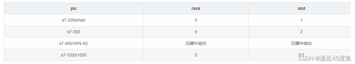
注意选对PLC的机架号和槽号,西门子不同系列PLC不同,200smart默认不需要设置
-
-
200smart 没有DB块,DBNum只有设置1
-
通讯类型设置 SetConnectionType(3),S7不同模式对通讯影响不同,这里设置3,
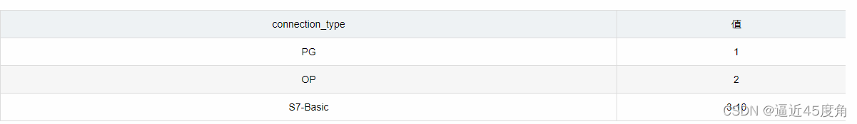
-
编译 下载到UNO,在STEP 7-MicroWIN上链接PLC在线修改变量,观察串口打印数据的是否变化
/*----------------------------------------------------------------------

Data Read Demo


Created  12 Dec 2016

Modified 10 Mar 2019 for Settimino 2.0.0

by Davide Nardella

------------------------------------------------------------------------

This demo shows how to read data from the PLC.

A DB with at least 1024 byte into the PLC is needed.

Specify its number into DBNum variable


- Both small and large data transfer are performed (see DO_IT_SMALL)

- During the loop, try to disconnect the ethernet cable.

  The system will report the error and will reconnect automatically

  when you re-plug the cable.

- For safety, this demo *doesn't write* data into the PLC, try

  yourself to change ReadArea with WriteArea.

- This demo uses ConnectTo() with Rack=0 and Slot=2 (S7300)

  - If you want to connect to S71200/S71500 change them to Rack=0, Slot=0.

  - If you want to connect to S7400 see your hardware configuration.

  - If you want to work with a LOGO 0BA7 or S7200 please refer to the

    documentation and change

    Client.ConnectTo(<IP>, <Rack>, <Slot>);

    with the couple

    Client.SetConnectionParams(<IP>, <LocalTSAP>, <Remote TSAP>);

    Client.Connect();


----------------------------------------------------------------------*/

#include "Platform.h"

#include "Settimino.h"


// Uncomment next line to perform small and fast data access

#define DO_IT_SMALL


// Enter a MAC address and IP address for your controller below.

// The IP address will be dependent on your local network:

byte mac[] = {

  0x90, 0xA2, 0xDA, 0x0F, 0x08, 0xE1 };


IPAddress Local(192,168,1,1); // Local Address

IPAddress PLC(192,168,1,31);   // PLC Address


// Following constants are needed if you are connecting via WIFI

// The ssid is the name of my WIFI network (the password obviously is wrong)

char ssid[] = "SKYNET-AIR";    // Your network SSID (name)

char pass[] = "yourpassword";  // Your network password (if any)

IPAddress Gateway(192, 168, 1, 1);

IPAddress Subnet(255, 255, 255, 0);


int DBNum = 1; // This DB must be present in your PLC

byte Buffer[1024];


S7Client Client;


unsigned long Elapsed; // To calc the execution time

//----------------------------------------------------------------------

// Setup : Init Ethernet and Serial port

//----------------------------------------------------------------------

void setup() {

    // Open serial communications and wait for port to open:

    Serial.begin(115200);

//--------------------------------Wired Ethernet Shield Initialization

    // Start the Ethernet Library

    EthernetInit(mac, Local);

    // Setup Time, someone said me to leave 2000 because some

    // rubbish compatible boards are a bit deaf.

    delay(2000);

    Serial.println("");

    Serial.println("Cable connected");

    Serial.print("Local IP address : ");

    Serial.println(Ethernet.localIP());

}

//----------------------------------------------------------------------

// Connects to the PLC

//----------------------------------------------------------------------

bool Connect()

{

    int Result=Client.ConnectTo(PLC,

                                  0,  // Rack (see the doc.)

                                  1); // Slot (see the doc.)

    Serial.print("Connecting to ");Serial.println(PLC);

    if (Result==0)

    {

      Serial.print("Connected ! PDU Length = ");Serial.println(Client.GetPDULength());

    }

    else

      Serial.println("Connection error");

    return Result==0;

}

//----------------------------------------------------------------------

// Dumps a buffer (a very rough routine)

//----------------------------------------------------------------------

void Dump(void *Buffer, int Length)

{

  int i, cnt=0;

  pbyte buf;


  if (Buffer!=NULL)

    buf = pbyte(Buffer);

  else

    buf = pbyte(&PDU.DATA[0]);


  Serial.print("[ Dumping ");Serial.print(Length);

  Serial.println(" bytes ]===========================");

  for (i=0; i<Length; i++)

  {

    cnt++;

    if (buf[i]<0x10)

      Serial.print("0");

    Serial.print(buf[i], HEX);

    Serial.print(" ");

    if (cnt==16)

    {

      cnt=0;

      Serial.println();

    }

  }

  Serial.println("===============================================");

}

//----------------------------------------------------------------------

// Prints the Error number

//----------------------------------------------------------------------

void CheckError(int ErrNo)

{

  Serial.print("Error No. 0x");

  Serial.println(ErrNo, HEX);


  // Checks if it's a Severe Error => we need to disconnect

  if (ErrNo & 0x00FF)

  {

    Serial.println("SEVERE ERROR, disconnecting.");

    Client.Disconnect();

  }

}

//----------------------------------------------------------------------

// Profiling routines

//----------------------------------------------------------------------

void MarkTime()

{

  Elapsed=millis();

}

//----------------------------------------------------------------------

void ShowTime()

{

  // Calcs the time

  Elapsed=millis()-Elapsed;

  Serial.print("Job time (ms) : ");

  Serial.println(Elapsed);

}

//----------------------------------------------------------------------

// Main Loop

//----------------------------------------------------------------------

void loop()

{

  int Size, Result;

  void *Target;


#ifdef DO_IT_SMALL

  Size=64;

  Target = NULL; // Uses the internal Buffer (PDU.DATA[])

#else

  Size=1024;

  Target = &Buffer; // Uses a larger buffer

#endif

  //Client.SetConnectionParams(Local,0x0100,0x0101);

  Client.SetConnectionType(3);

  // Connection

  while (!Client.Connected)

  {

    if (!Connect())

      delay(500);

  }


  Serial.print("Reading ");Serial.print(Size);Serial.print(" bytes from DB");Serial.println(DBNum);

  // Get the current tick

  MarkTime();

  Result=Client.ReadArea(S7AreaDB, // We are requesting DB access

                         DBNum,    // DB Number

                         0,        // Start from byte N.0

                         Size,     // We need "Size" bytes

                         Target);  // Put them into our target (Buffer or PDU)

  if (Result==0)

  {

    ShowTime();

    Dump(Target, Size);

  }

  else

    CheckError(Result);


  delay(1000);

}


 184
184

 被折叠的 条评论
为什么被折叠?
被折叠的 条评论
为什么被折叠?
 到【灌水乐园】发言


