


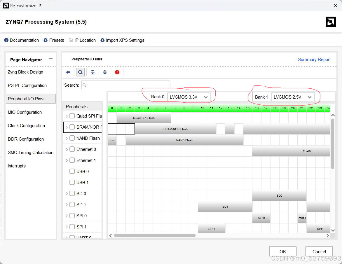
1、首先确保vivado中bank0和bank1的电压设置是否符合原理图,蚂蚁s9中bank0为3.3v,bank1为2.5v。
2、确保代码编写无问题,这里使用正点原子的代码。
首先初始化串口:
int uart_init(XUartPs *uart_ps) {
    int status;
    XUartPs_Config *uart_cfg;

    uart_cfg = XUartPs_LookupConfig(UART_DEVICE_BASEADDR);
    if (NULL == uart_cfg)
        return XST_FAILURE;
    status = XUartPs_CfgInitialize(uart_ps, uart_cfg, uart_cfg->BaseAddress);
    if (status != XST_SUCCESS)
        return XST_FAILURE;
    // UART 设备自检
    status = XUartPs_SelfTest(uart_ps);
    if (status != XST_SUCCESS)
        return XST_FAILURE;
    //设置工作模式:正常模式
    XUartPs_SetOperMode(uart_ps, XUARTPS_OPER_MODE_NORMAL);
    //设置波特率:115200
    XUartPs_SetBaudRate(uart_ps, 115200);
    //设置 RxFIFO 的中断触发等级
    XUartPs_SetFifoThreshold(uart_ps, 1);

    return XST_SUCCESS;
}
再初始化中断:
//串口中断初始化
int uart_intr_init(XScuGic *intc, XUartPs *uart_ps) {
    int status;
    // XUartPs_Config *Config;
    //初始化中断控制器
    XScuGic_Config *intc_cfg;
    intc_cfg = XScuGic_LookupConfig(INTC_DEVICE_ID);
    if (NULL == intc_cfg)
        return XST_FAILURE;
    status = XScuGic_CfgInitialize(intc, intc_cfg, intc_cfg->CpuBaseAddress);
    if (status != XST_SUCCESS)
        return XST_FAILURE;

    //设置并打开中断异常处理功能
    Xil_ExceptionInit();
    Xil_ExceptionRegisterHandler(XIL_EXCEPTION_ID_INT,
                                (Xil_ExceptionHandler)XScuGic_InterruptHandler,
                                (void *)intc);
    Xil_ExceptionEnable();

    //为中断设置中断处理函数
    XScuGic_Connect(intc, UART_INT_IRQ_ID,
                    (Xil_ExceptionHandler)uart_intr_handler, (void *)uart_ps);
    //设置 UART 的中断触发方式
    XUartPs_SetInterruptMask(uart_ps, UART_INT_MASK);
    //使能 GIC 中的串口中断
    XScuGic_Enable(intc, UART_INT_IRQ_ID);

    return XST_SUCCESS;
}
中断处理函数:
// UART 中断处理函数
void uart_intr_handler(void *call_back_ref) {
    XUartPs *uart_instance_ptr = (XUartPs *)call_back_ref;
    u32 rec_data = 0;
    u32 isr_status; //中断状态标志

    //读取中断 ID 寄存器,判断触发的是哪种中断
    isr_status = XUartPs_ReadReg(uart_instance_ptr->Config.BaseAddress,
                                XUARTPS_IMR_OFFSET);
    isr_status &= XUartPs_ReadReg(uart_instance_ptr->Config.BaseAddress,
                                    XUARTPS_ISR_OFFSET);

    //判断中断标志位 RxFIFO 是否触发
    if (isr_status & (u32)UART_INT_MASK) {//XUARTPS_IXR_RXOVR
        rec_data = XUartPs_RecvByte(UART_DEVICE_BASEADDR);
        // XUartPs_SendByte(UART_DEVICE_BASEADDR, 'F');
        //清除中断标志
        XUartPs_WriteReg(uart_instance_ptr->Config.BaseAddress,
                        XUARTPS_ISR_OFFSET,
                        UART_INT_MASK);//XUARTPS_IXR_RXOVR
    }
    XUartPs_SendByte(UART_DEVICE_BASEADDR, rec_data);
}
主函数:
// main 函数
int main(void) {
    int status;
    u32 temp=0;

    status = uart_init(&Uart_Ps); //串口初始化
    if (status == XST_FAILURE) {
        xil_printf("Uart Initial Failed\r\n");
        return XST_FAILURE;
    }
    xil_printf("uart interrupt test!\r\n");
    status = uart_intr_init(&Intc, &Uart_Ps); //串口中断初始化
    if (status == XST_FAILURE) {
        xil_printf("Uart Intr Initial Failed\r\n");
        return XST_FAILURE;
    }
    while (1){

    }
    return status;
}要注意的是我用的vitis24.1版本中UART_DEVICE_ID应当改为UART_DEVICE_BASEADDR,使用XPAR_UART1_BASEADDR宏。这是因为引入了SDT。
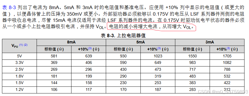
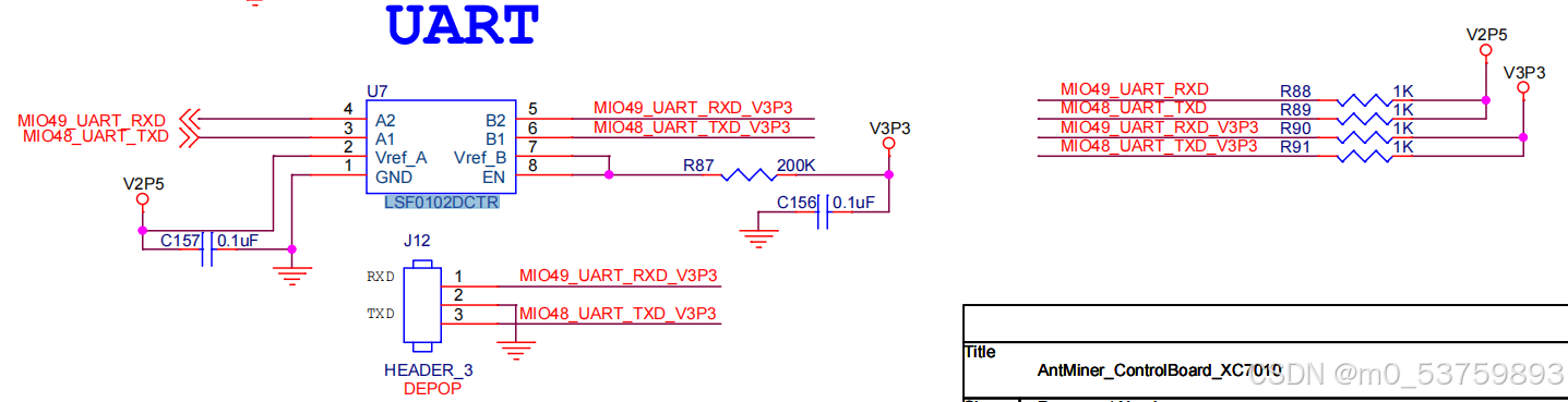
3、确保代码没问题了,可以开始改硬件了。一开始我一直以为是由于软件版本太高,导致正点原子代码不能直接运行,需要修改,然后我没有改好从而导致一直进不去接收中断,后面使用示波器查看波形才发现,RX引脚电压一直为高电平,然后开始考虑是硬件的问题了。刚开始以为是usb转ttl模块下拉能力不足,就把板子rx 3.3v上拉电阻增大,发现rx低电平电压下降了些许,但还不够。最后看了串口电平转换芯片LSF0102DCTR手册,发现了这一句:“电阻的减小将增大电流,从而增大Vol。”于是将2.5V上拉电阻R88增大到100K,此时波形正常,程序也能正常运行了。


 1万+
1万+

 被折叠的 条评论
为什么被折叠?
被折叠的 条评论
为什么被折叠?
 到【灌水乐园】发言


