


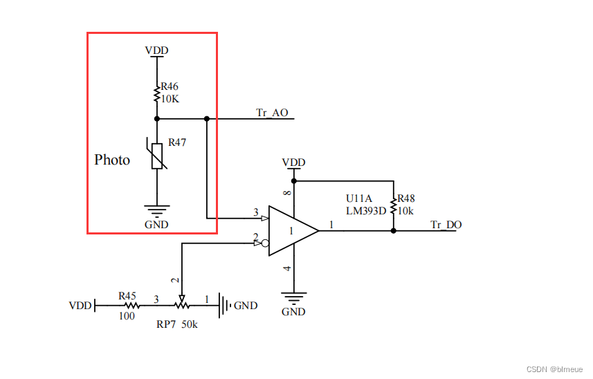
1.原理图
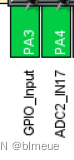
2.CUbemx配置
3.代码
(1)dadc.c
#include "dadc.h"
double getADC(ADC_HandleTypeDef *pin)
{
    unsigned int value;
    //开启ADC
    HAL_ADC_Start(pin);

    //获取ADC的值
    value=HAL_ADC_GetValue(pin);

    //12位精度即4096
    //4096就代表3.3V
    return value*(3.3/4096);
}
(2)dadc.h
#ifndef __DADC_H__
#define __DADC_H__

#include "main.h"
double getADC(ADC_HandleTypeDef *pin);


#endif
(3)main.c
/* USER CODE BEGIN Header */
/**
  ******************************************************************************
  * @file           : main.c
  * @brief          : Main program body
  ******************************************************************************
  * @attention
  *
  * Copyright (c) 2024 STMicroelectronics.
  * All rights reserved.
  *
  * This software is licensed under terms that can be found in the LICENSE file
  * in the root directory of this software component.
  * If no LICENSE file comes with this software, it is provided AS-IS.
  *
  ******************************************************************************
  */
/* USER CODE END Header */
/* Includes ------------------------------------------------------------------*/
#include "main.h"
#include "adc.h"
#include "gpio.h"

/* Private includes ----------------------------------------------------------*/
/* USER CODE BEGIN Includes */


#include "lcd.h"
#include "led.h"
#include "dadc.h"
#include "stdio.h"
#include "string.h"

/* USER CODE END Includes */

/* Private typedef -----------------------------------------------------------*/
/* USER CODE BEGIN PTD */

unsigned char ucled=0x00;

unsigned char lcd_text[30];

__IO uint32_t uwTick_Lcd;
__IO uint32_t uwTick_Adc;

double adc2_in17_AO1;
double adc2_in13_AO2;

//下面两个是光敏电阻的参数
double trao;//光敏电阻电压值
unsigned char trdo;//PA3(TRDO是数字输出口)接收的电平只有0V和3.3V,比较光敏电阻电压和可调变阻器的电压之后的输出值

/* USER CODE END PTD */

/* Private define ------------------------------------------------------------*/
/* USER CODE BEGIN PD */

/* USER CODE END PD */

/* Private macro -------------------------------------------------------------*/
/* USER CODE BEGIN PM */

/* USER CODE END PM */

/* Private variables ---------------------------------------------------------*/

/* USER CODE BEGIN PV */

/* USER CODE END PV */

/* Private function prototypes -----------------------------------------------*/
void SystemClock_Config(void);
/* USER CODE BEGIN PFP */
void lcd_proc(void);
void adc_proc(void);

/* USER CODE END PFP */

/* Private user code ---------------------------------------------------------*/
/* USER CODE BEGIN 0 */

/* USER CODE END 0 */

/**
  * @brief  The application entry point.
  * @retval int
  */
int main(void)
{
  /* USER CODE BEGIN 1 */

  /* USER CODE END 1 */

  /* MCU Configuration--------------------------------------------------------*/

  /* Reset of all peripherals, Initializes the Flash interface and the Systick. */
  HAL_Init();

  /* USER CODE BEGIN Init */

  /* USER CODE END Init */

  /* Configure the system clock */
  SystemClock_Config();

  /* USER CODE BEGIN SysInit */

  /* USER CODE END SysInit */

  /* Initialize all configured peripherals */
  MX_GPIO_Init();
  MX_ADC2_Init();
  /* USER CODE BEGIN 2 */

    LCD_Init();
    LCD_Clear(Black);
    LCD_SetBackColor(Black);
    LCD_SetTextColor(White);

    led_disp(ucled);

  /* USER CODE END 2 */

  /* Infinite loop */
  /* USER CODE BEGIN WHILE */
  while (1)
  {
    /* USER CODE END WHILE */

    /* USER CODE BEGIN 3 */
//     adc2_in17_AO1=getADC(&hadc2);
//    //HAL_Delay(2);
//    adc2_in13_AO2=getADC(&hadc2);
      adc_proc();
      lcd_proc();
  }
  /* USER CODE END 3 */
}

/**
  * @brief System Clock Configuration
  * @retval None
  */
void SystemClock_Config(void)
{
  RCC_OscInitTypeDef RCC_OscInitStruct = {0};
  RCC_ClkInitTypeDef RCC_ClkInitStruct = {0};

  /** Configure the main internal regulator output voltage
  */
  HAL_PWREx_ControlVoltageScaling(PWR_REGULATOR_VOLTAGE_SCALE1);

  /** Initializes the RCC Oscillators according to the specified parameters
  * in the RCC_OscInitTypeDef structure.
  */
  RCC_OscInitStruct.OscillatorType = RCC_OSCILLATORTYPE_HSE;
  RCC_OscInitStruct.HSEState = RCC_HSE_ON;
  RCC_OscInitStruct.PLL.PLLState = RCC_PLL_ON;
  RCC_OscInitStruct.PLL.PLLSource = RCC_PLLSOURCE_HSE;
  RCC_OscInitStruct.PLL.PLLM = RCC_PLLM_DIV3;
  RCC_OscInitStruct.PLL.PLLN = 20;
  RCC_OscInitStruct.PLL.PLLP = RCC_PLLP_DIV2;
  RCC_OscInitStruct.PLL.PLLQ = RCC_PLLQ_DIV2;
  RCC_OscInitStruct.PLL.PLLR = RCC_PLLR_DIV2;
  if (HAL_RCC_OscConfig(&RCC_OscInitStruct) != HAL_OK)
  {
    Error_Handler();
  }

  /** Initializes the CPU, AHB and APB buses clocks
  */
  RCC_ClkInitStruct.ClockType = RCC_CLOCKTYPE_HCLK|RCC_CLOCKTYPE_SYSCLK
                              |RCC_CLOCKTYPE_PCLK1|RCC_CLOCKTYPE_PCLK2;
  RCC_ClkInitStruct.SYSCLKSource = RCC_SYSCLKSOURCE_PLLCLK;
  RCC_ClkInitStruct.AHBCLKDivider = RCC_SYSCLK_DIV1;
  RCC_ClkInitStruct.APB1CLKDivider = RCC_HCLK_DIV1;
  RCC_ClkInitStruct.APB2CLKDivider = RCC_HCLK_DIV1;

  if (HAL_RCC_ClockConfig(&RCC_ClkInitStruct, FLASH_LATENCY_2) != HAL_OK)
  {
    Error_Handler();
  }
}

/* USER CODE BEGIN 4 */

void adc_proc(void)
{
    if((uwTick-uwTick_Adc)<100)return;
    uwTick_Adc=uwTick;

        trao=adc2_in17_AO1;

    trdo=HAL_GPIO_ReadPin(GPIOA,GPIO_PIN_3);

    //读取RANK1的电压
    adc2_in17_AO1=getADC(&hadc2);
    //读取RANK2的电压
    adc2_in13_AO2=getADC(&hadc2);


}

void lcd_proc(void)
{
    if((uwTick-uwTick_Lcd)<100)return;
    uwTick_Lcd=uwTick;

//    Get_Adc(&hadc2);


    memset(lcd_text,0,sizeof(lcd_text));
    sprintf((char *)lcd_text,"in17:%0.2fV in13:%0.2fV",adc2_in17_AO1,adc2_in13_AO2);
    LCD_DisplayStringLine(Line2,lcd_text);

    memset(lcd_text,0,sizeof(lcd_text));
    sprintf((char *)lcd_text,"trao:%0.2fV trdo:%d",trao,trdo);
    LCD_DisplayStringLine(Line6,lcd_text);
}

/* USER CODE END 4 */

/**
  * @brief  This function is executed in case of error occurrence.
  * @retval None
  */
void Error_Handler(void)
{
  /* USER CODE BEGIN Error_Handler_Debug */
  /* User can add his own implementation to report the HAL error return state */
  __disable_irq();
  while (1)
  {
  }
  /* USER CODE END Error_Handler_Debug */
}

#ifdef  USE_FULL_ASSERT
/**
  * @brief  Reports the name of the source file and the source line number
  *         where the assert_param error has occurred.
  * @param  file: pointer to the source file name
  * @param  line: assert_param error line source number
  * @retval None
  */
void assert_failed(uint8_t *file, uint32_t line)
{
  /* USER CODE BEGIN 6 */
  /* User can add his own implementation to report the file name and line number,
     ex: printf("Wrong parameters value: file %s on line %d\r\n", file, line) */
  /* USER CODE END 6 */
}
#endif /* USE_FULL_ASSERT */
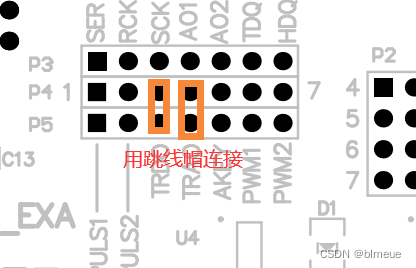
4.扩展板上跳线帽的连接
5.源码
gitee:gitee——扩展板上光敏电阻的电压采集
github:github——扩展板上光敏电阻的电压采集


 2410
2410


 被折叠的 条评论
为什么被折叠?
被折叠的 条评论
为什么被折叠?
 到【灌水乐园】发言


