


配置步骤:
1.配置IP地址
R1:
sys
sys R1
interface GigabitEthernet 0/0/0
ip add 192.168.100.9 30
int g 4/0/0
ip add 10.10.10.41 30
int g 0/0/2
ip add 192.168.100.17 30
int g 0/0/1
ip add 10.10.10.1 30
int g 4/0/1
ip add 10.10.10.5 30
qu
interface LoopBack 0
ip address 1.1.1.1 32
qu
R2:
sys
sys R2
int g 0/0/0
ip add 192.168.100.13 30
int g 0/0/2
ip add 10.10.10.42 30
int g 0/0/1
ip add 192.168.100.5 30
int g 4/0/1
ip add 10.10.10.13 30
int g 4/0/0
ip add 10.10.10.9 30
qu
interface LoopBack 0
ip address 2.2.2.2 32
qu
R3:
sys
sys R3
int g 0/0/0
ip add 192.168.100.10 30
int g 0/0/1
ip add 192.168.1.254 24
int g 0/0/2
ip add 192.168.100.1 30
int g 4/0/0
ip add 192.168.100.6 30
qu
R4:
sys
sys R4
int g 0/0/0
ip add 192.168.100.14 30
int g 0/0/1
ip add 192.168.2.254 24
int g 0/0/2
ip add 192.168.100.2 30
int g 4/0/0
ip add 192.168.100.18 30
qu
R5:
sys
sys R5
int g 0/0/0
ip add 10.10.10.2 30
int g 0/0/1
ip add 10.10.10.10 30
int g 4/0/0
ip add 10.10.10.21 30
int g 0/0/2
ip add 10.10.10.17 30
qu
interface LoopBack 0
ip add 5.5.5.5 32
R6:
sys
sys R6
int g 0/0/1
ip add 10.10.10.14 30
int g 0/0/2
ip add 10.10.10.6 30
int g 4/0/0
ip add 10.10.10.25 30
int g 0/0/0
ip add 10.10.10.18 30
qu
interface LoopBack 0
ip add 6.6.6.6 32
qu
R7:
sys
sys R7
int g 0/0/0
ip add 10.10.10.22 30
int g 0/0/1
ip add 10.10.10.26 30
int g 4/0/0
ip add 10.10.10.29 30
int g 0/0/2
ip add 10.10.10.33 30
qu
interface LoopBack 0
ip add 7.7.7.7 32
qu
R8:
sys
sys R8
int g 0/0/1
ip add 10.10.10.30 30
int g 0/0/0
ip add 10.10.10.34 30
int g 0/0/2
ip add 10.10.10.37 30
qu
interface LoopBack 0
ip add 8.8.8.8 32
qu
R9:
sys
sys R9
int g 0/0/0
ip add 10.10.10.38 30
int g 0/0/1
ip add 192.168.200.2 30
qu
R10:
[R10-GigabitEthernet0/0/0]ip address 192.168.200.1 30[R10-LoopBack0]ip address 10.10.10.10 32[R10]int g0/0/1.1
[R10-GigabitEthernet0/0/1.1]dot1q termination vid 10[R10-GigabitEthernet0/0/1.1]ip address 192.168.3.254 24[R10-GigabitEthernet0/0/1.1]arp broadcast enable [R10]int g0/0/1.2 [R10-GigabitEthernet0/0/1.2]dot1q termination vid 20[R10-GigabitEthernet0/0/1.2]ip address 192.168.4.254 24[R10-GigabitEthernet0/0/1.2]arp broadcast enable
2.配置VLAN
[sw3]vlan batch 10 20[sw3-GigabitEthernet0/0/1]port link-type trunk [sw3-GigabitEthernet0/0/1]port trunk allow-pass vlan all
[sw3-GigabitEthernet0/0/2]port link-type access
[sw3-GigabitEthernet0/0/2]port default vlan 10
[sw3-GigabitEthernet0/0/3]port link-type access
[sw3-GigabitEthernet0/0/3]port default vlan 20
3.起ospf宣告 (对外宣告的接口都不宣告)
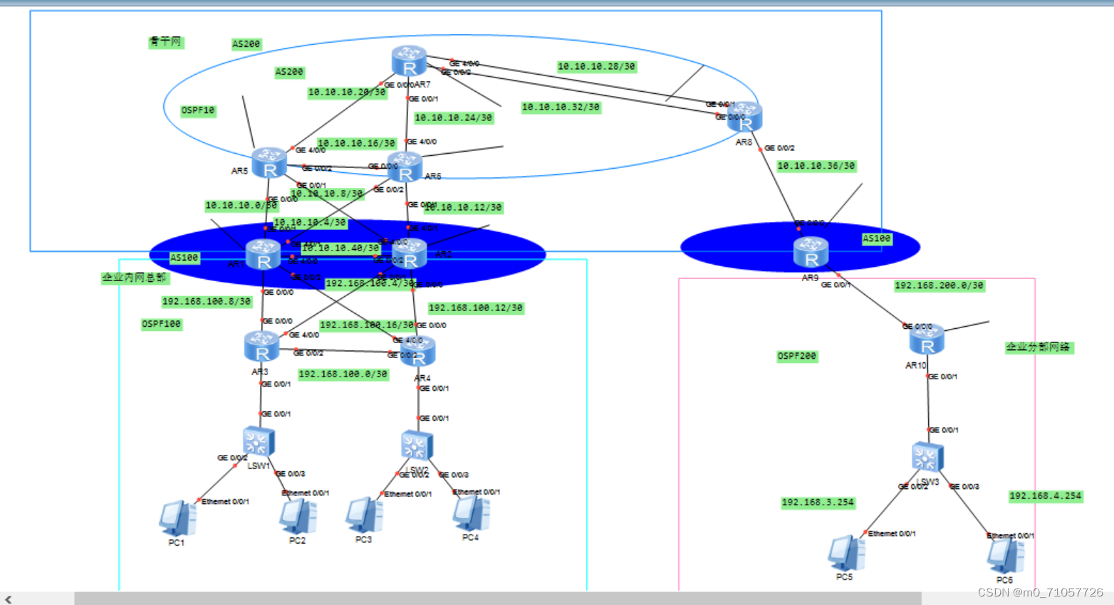
分析:先从企业内网总部开始,其中有R1 R2 R3 R4四台路由器 宣告ospf
R1:
[R1]ospf 100- router-id 1.1.1.1[R1-ospf-100--area-0.0.0.0]network 10.10.10.41 0.0.0.0[R1-ospf-100--area-0.0.0.0]network 192.168.100.9 0.0.0.0[R1-ospf-100--area-0.0.0.0]network 192.168.100.17 0.0.0.0
[R1-ospf-100-area-0.0.0.0]network 1.1.1.1 0.0.0.0
R2:
[R2]ospf 100- ro-uter-id 2.2.2.2
[R2-ospf-100--area-0.0.0.0]network 10.10.10.42 0.0.0.0
[R2-ospf-100--area-0.0.0.0]network 192.168.100.5 0.0.0.0[R2-ospf-100--area-0.0.0.0]network 192.168.100.13 0.0.0.0
[R2-ospf-100-area-0.0.0.0]network 2.2.2.2 0.0.0.0
R3:
[R3]ospf 100-router-id 3.3.3.3 [R3-ospf-100--area-0.0.0.0]network 192.168.100.1 0.0.0.0[R3-ospf-100--area-0.0.0.0]network 192.168.100.6 0.0.0.0
[R3-ospf-100--area-0.0.0.0]network 192.168.100.10 0.0.0.0
[R3-ospf-100--area-0.0.0.0]network 192.168.1.254 0.0.0.0
R4:
[R4]ospf100- router-id 4.4.4.4 [R4-ospf-100--area-0.0.0.0]network 192.168.100.2 0.0.0.0
[R4-ospf-100-area-0.0.0.0]network 192.168.100.14 0.0.0.0
[R4-ospf-100-area-0.0.0.0]network 192.168.2.254 0.0.0.0
[R4-ospf-100-area-0.0.0.0]network 192.168.100.18 0.0.0.0
此时总部的OSPF就跑完了 接下来跑骨干网的
R5:
[R5]ospf 10 router-id 5.5.5.5[R5-ospf-10-area-0.0.0.0]network 10.10.10.21 0.0.0.0[R5-ospf-10-area-0.0.0.0]network 10.10.10.17 0.0.0.0
[R5-ospf-10-area-0.0.0.0]network 5.5.5.5 0.0.0.0
R6:
[R6]ospf 10 router-id 6.6.6.6[R6-ospf-10-area-0.0.0.0]network 10.10.10.25 0.0.0.0[R6-ospf-10-area-0.0.0.0]network 10.10.10.18 0.0.0.0
[R6-ospf-10-area-0.0.0.0]network 6.6.6.6 0.0.0.0
R7:
[R7]ospf 10 router-id 7.7.7.7
[R7-ospf-10-area-0.0.0.0]network 10.10.10.22 0.0.0.0
[R7-ospf-10-area-0.0.0.0]network 10.10.10.26 0.0.0.0
[R7-ospf-10-area-0.0.0.0]network 10.10.10.29 0.0.0.0[R7-ospf-10-area-0.0.0.0]network 10.10.10.33 0.0.0.0[R7-ospf-10-area-0.0.0.0]network 7.7.7.7 0.0.0.0
R8:
[R8]ospf 10 router-id 8.8.8.8[R8-ospf-10-area-0.0.0.0]network 8.8.8.8 0.0.0.0 [R8-ospf-10-area-0.0.0.0]network 10.10.10.30 0.0.0.0
[R8-ospf-10-area-0.0.0.0]network 10.10.10.34 0.0.0.0
R9:[R9]ospf 200 router-id 9.9.9.9[R9-ospf-200-area-0.0.0.0]network 192.168.200.2 0.0.0.0
R10:
[R10]ospf 200 router-id 10.10.10.10[R10-ospf-200-area-0.0.0.0]network 192.168.200.1 0.0.0.0
[R10-ospf-200-area-0.0.0.0]network 192.168.3.254 0.0.0.0[R10-ospf-200-area-0.0.0.0]network 192.168.4.254 0.0.0.0
此时IBGPs上的写完了
检查一下IBGP上的通不通(看邻居)
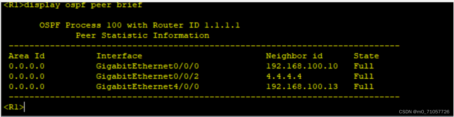
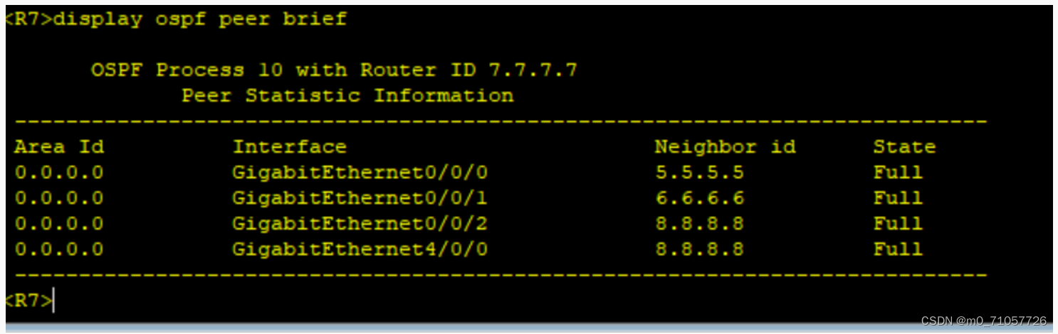
全部查一下 看是否FULL
接下来开始跑BGP
先从总部开始 总部只有R1 R2 有bgp (实验要求:IBGP是环回 EBGP是直连)
开始建邻
R1 R2建邻
R1:[R1-bgp]router-id 1.1.1.1[R1-bgp]peer 2.2.2.2 as-number 100[R1-bgp]peer 2.2.2.2 connect-interface LoopBack 0
R2:
[R2-bgp]router-id 2.2.2.2 [R2-bgp]peer 1.1.1.1 as-number 100[R2-bgp]peer 1.1.1.1 connect-interface LoopBack 0
然后再R1与R5和T6
[R1-bgp]peer 10.10.10.2 as-number 200 ---R5[R1-bgp]peer 10.10.10.6 as-number 200 ----R6
R2与R5和R6
[R2-bgp]peer 10.10.10.10 as-number 200 [R2-bgp]peer 10.10.10.14 as-number 200
然后骨干网是全连的BGP关系 所以5678全是BGP
R5上:
[R5-bgp]router-id 5.5.5.5 [R5-bgp]peer 10.10.10.1 as-number 100 ---R1[R5-bgp]peer 10.10.10.9 as-number 100 ---R2[R5-bgp]peer 6.6.6.6 as-number 200[R5-bgp]peer 6.6.6.6 connect-interface LoopBack 0[R5-bgp]peer 6.6.6.6 next-hop-local [R5-bgp]peer 7.7.7.7 as-number 200[R5-bgp]peer 7.7.7.7 connect-interface LoopBack 0[R5-bgp]peer 7.7.7.7 next-hop-local [R5-bgp]peer 8.8.8.8 as-number 200 [R5-bgp]peer 8.8.8.8 connect-interface LoopBack 0[R5-bgp]peer 8.8.8.8 next-hop-local
R6:
[R6-bgp]router-id 6.6.6.6[R6-bgp]peer 5.5.5.5 as-number 200[R6-bgp]peer 5.5.5.5 connect-interface LoopBack 0[R6-bgp]peer 10.10.10.5 as-number 100 --R1[R6-bgp]peer 10.10.10.13 as-number 100 ---R2[R6-bgp]peer 7.7.7.7 as-number 200 [R6-bgp]peer 7.7.7.7 connect-interface LoopBack 0[R6-bgp]peer 7.7.7.7 next-hop-local [R6-bgp]peer 8.8.8.8 as-number 200 [R6-bgp]peer 8.8.8.8 connect-interface LoopBack 0[R6-bgp]peer 8.8.8.8 next-hop-local
R7:
[R7-bgp]router-id 7.7.7.7[R7-bgp]peer 5.5.5.5 as-number 200[R7-bgp]peer 5.5.5.5 connect-interface LoopBack 0[R7-bgp]peer 6.6.6.6 as-number 200[R7-bgp]peer 6.6.6.6 connect-interface LoopBack 0[R7-bgp]peer 8.8.8.8 as-number 200[R7-bgp]peer 8.8.8.8 connect-interface LoopBack 0
R8:
[R8-bgp]router-id 8.8.8.8[R8-bgp]peer 5.5.5.5 as-number 200[R8-bgp]peer 5.5.5.5 connect-interface LoopBack 0[R8-bgp]peer 5.5.5.5 next-hop-local [R8-bgp]peer 6.6.6.6 as-number 200 [R8-bgp]peer 6.6.6.6 connect-interface LoopBack 0[R8-bgp]peer 6.6.6.6 next-hop-local [R8-bgp]peer 7.7.7.7 as-number 200[R8-bgp]peer 7.7.7.7 connect-interface LoopBack 0[R8-bgp]peer 7.7.7.7 next-hop-local
[R8-bgp]peer 10.10.10.38 as-number 100
R9:
[R9-bgp]router-id 9.9.9.9[R9-bgp]peer 10.10.10.37 as-number 200
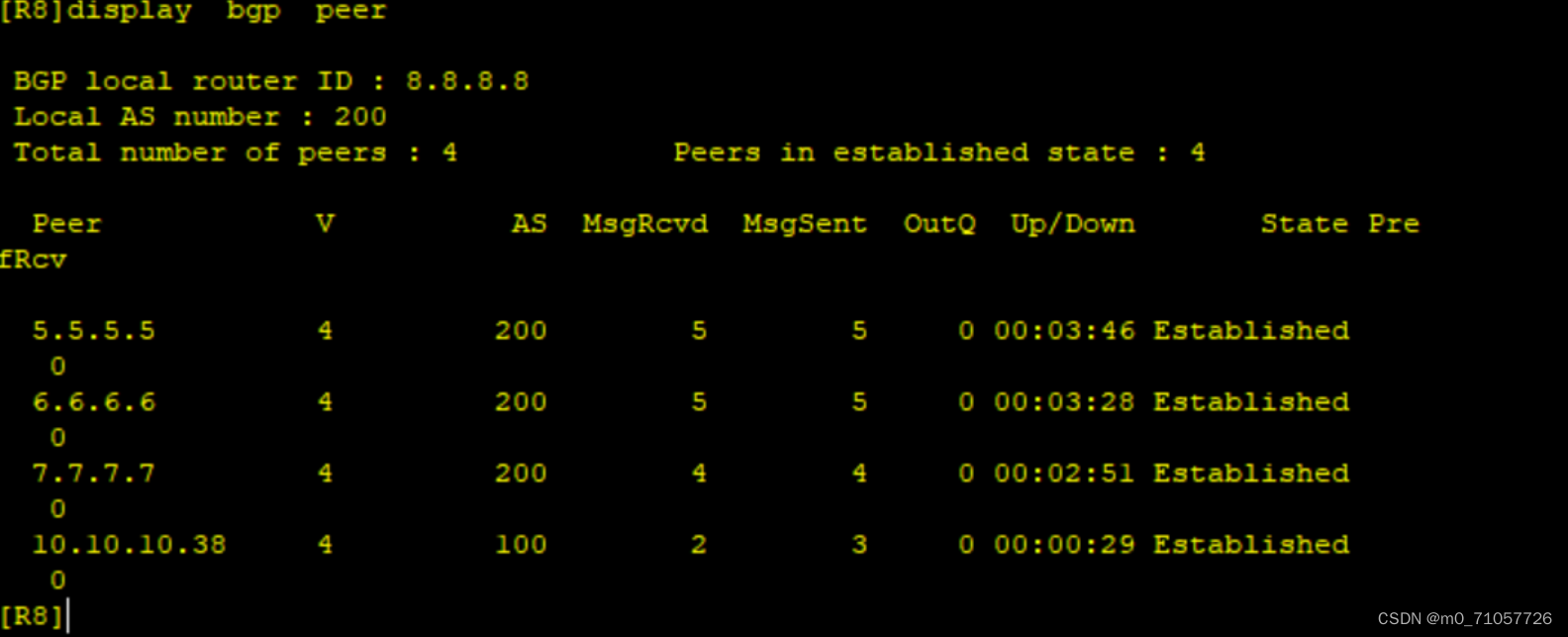
此时BGP写完 然后看邻居关系
接下来宣告用户网段(PC)
[R1-bgp]network 192.168.1.0 24[R1-bgp]network 192.168.2.0 24
[R2-bgp]network 192.168.1.0 24[R2-bgp]network 192.168.2.0 24
[R9-bgp]network 192.168.3.0 24[R9-bgp]network 192.168.4.0 24
此时查一下传到没有
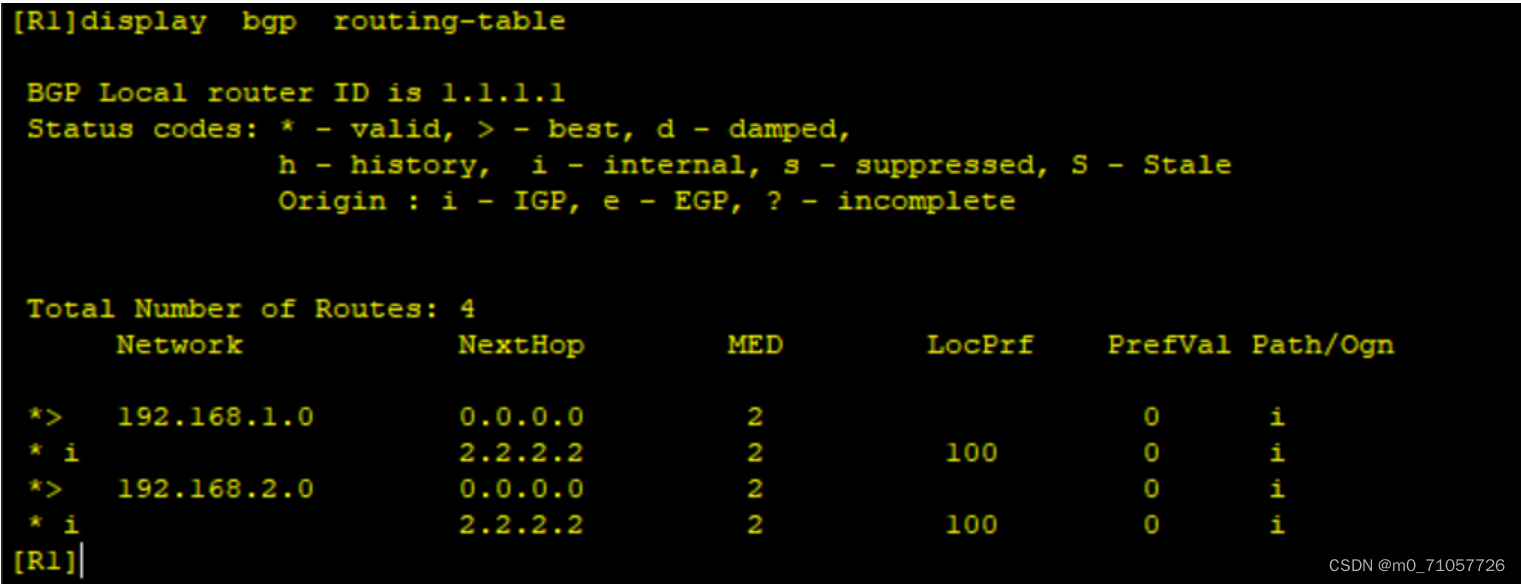
1上学不到3 4
因为3 4也在AS100里面 因为左边也是AS100 两个AS相同 水平分割 导致3 4 过不来
然后用到一个指令allow-as-loop---允许相同AS
[R1-bgp]peer 10.10.10.2 allow-as-loop [R1-bgp]peer 10.10.10.6 allow-as-loop
[R2-bgp]peer 10.10.10.10 allow-as-loop l[R2-bgp]peer 10.10.10.14 allow-as-loop
[R9-bgp]peer 10.10.10.37 allow-as-loop
此时再到R1上查看BGP表:
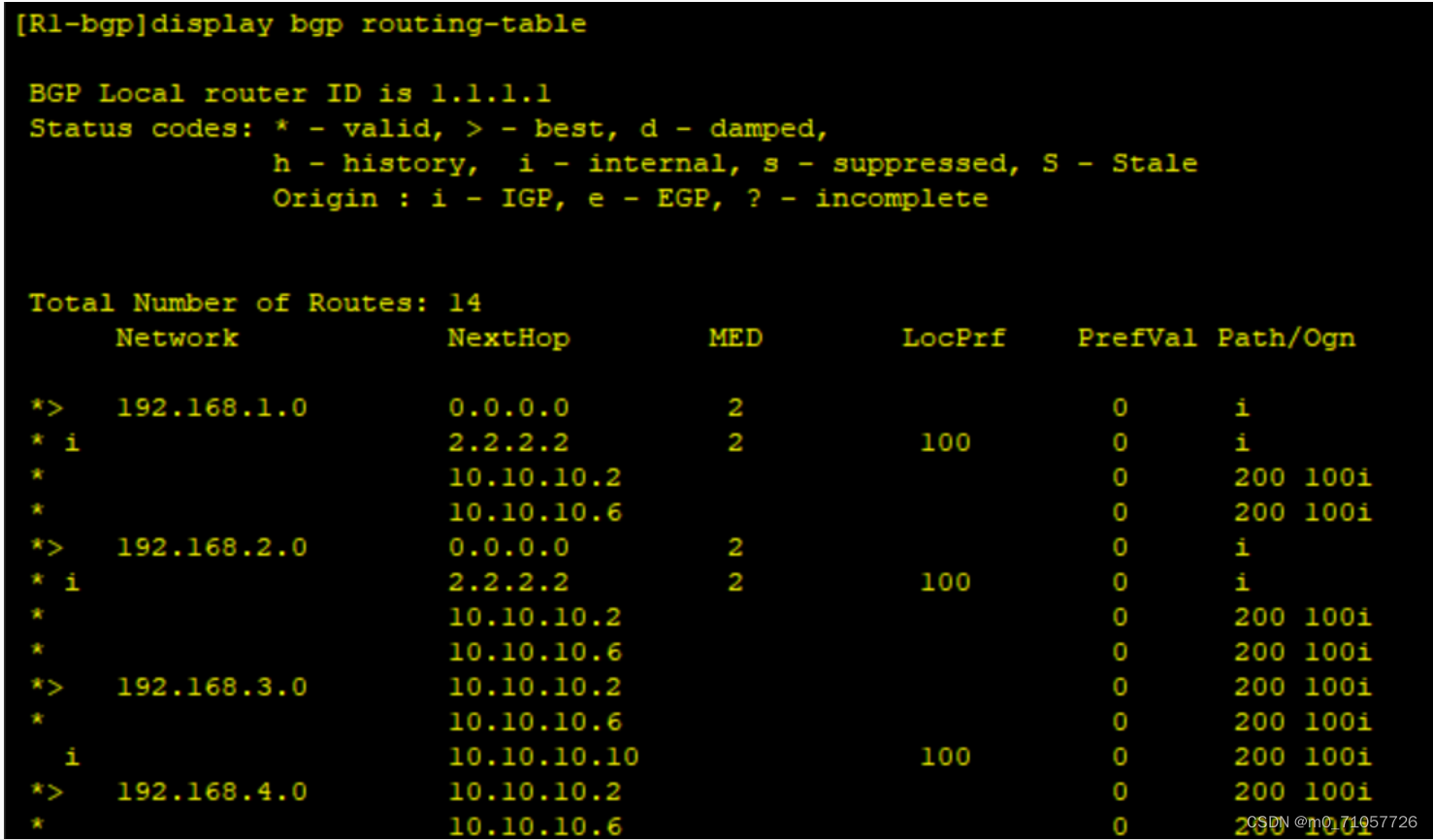
此时3 4都学学过来了
左边1.1 和 右边3.1 还是不能通 因为路由还没出现
所以要用到重发布
只需要在1 2 9里面把bgp的路由发布到ospf表里面
因为题目要求还要改类型 type-1
[R1-ospf-100]import-route bgp type 1
[R2-ospf-100]import-route bgp type 1
[R9-ospf-200]import-route bgp type 1
这么做相当于把bgp的路由引到ospf表里面
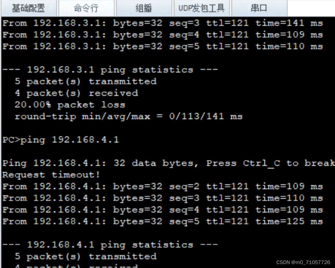
现在路由可达
去PC1上测试:
优先级150 显示重发布来的
重发布和EBGP它会选择重发布 为了公平起见 我们要让其保持一致
[R1-bgp]ipv4-family unicast [R1-bgp-af-ipv4]preference 140 255 255
[R2-bgp]ipv4-family unicast[R2-bgp-af-ipv4]preference 140 255 255
此时再到路由表上看其就是保持一致
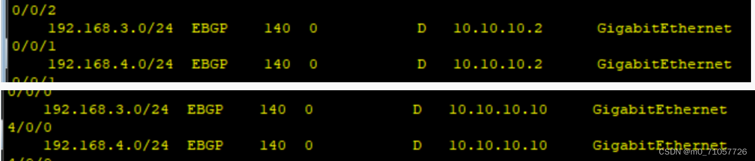
此时流量 2 1 都走 这样次优路径这个问题就解决掉了
<R3>ping -r -a 192.168.1.254 192.168.3.254
在R3上查 1.0默认走的是R2
在2.0 R4上
<R4>ping -r -a 192.168.2.254 192.168.3.254
走的是R1
刚好反过来了
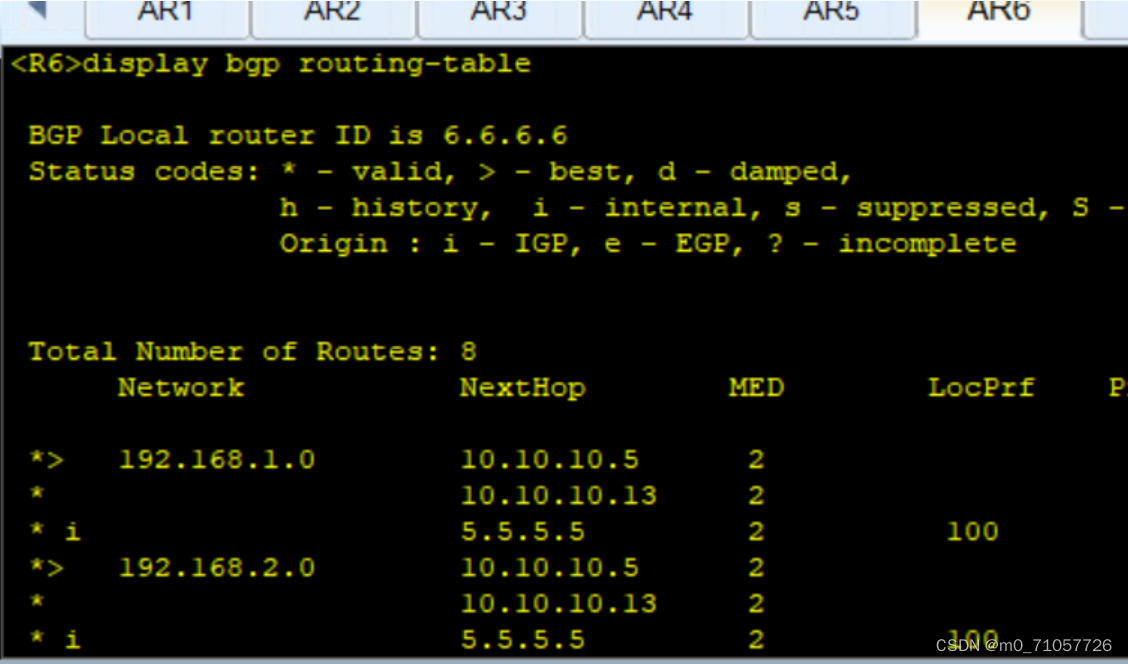
从5的角度看
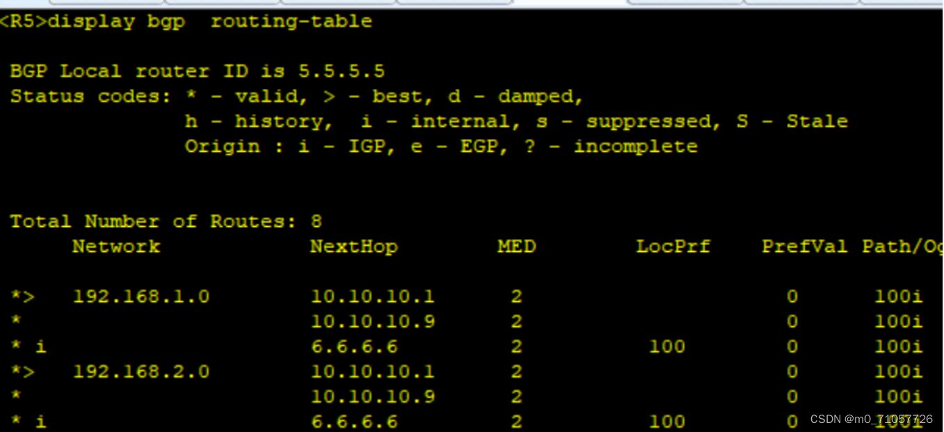
从5 6看都是R1 在前面
现在1.0走的R2 2.0走的1
现在要通过修改1 和2上面的参数让1.0 走R1 让2.0走R2
在1上抓2.0的流量给5 (把2.0的值med改大)
[R1]ip ip-prefix 1 permit 192.168.2.0 24 --在R1上把流量抓起来
[R1]route-policy 1 permit node 10[R1-route-policy]if-match ip-prefix 1 [R1-route-policy]apply cost 10[R1]route-policy 1 permit node 20
[R1-bgp]peer 10.10.10.2 route-policy 1 export[R1-bgp]peer 10.10.10.6 route-policy 1 export
[R2]ip ip-prefix 1 permit 192.168.1.0 24[R2]route-policy 1 permit node 10[R2-route-policy]if-match ip-prefix 1[R2-route-policy]apply cost 10 [R2]route-policy 1 permit node 20[R2-bgp]peer 10.10.10.10 route-policy 1 export [R2-bgp]peer 10.10.10.14 route-policy 1 export
此时再到5上看
保存重启一下
Reboot


 被折叠的 条评论
为什么被折叠?
被折叠的 条评论
为什么被折叠?
 到【灌水乐园】发言


