


第一个单片机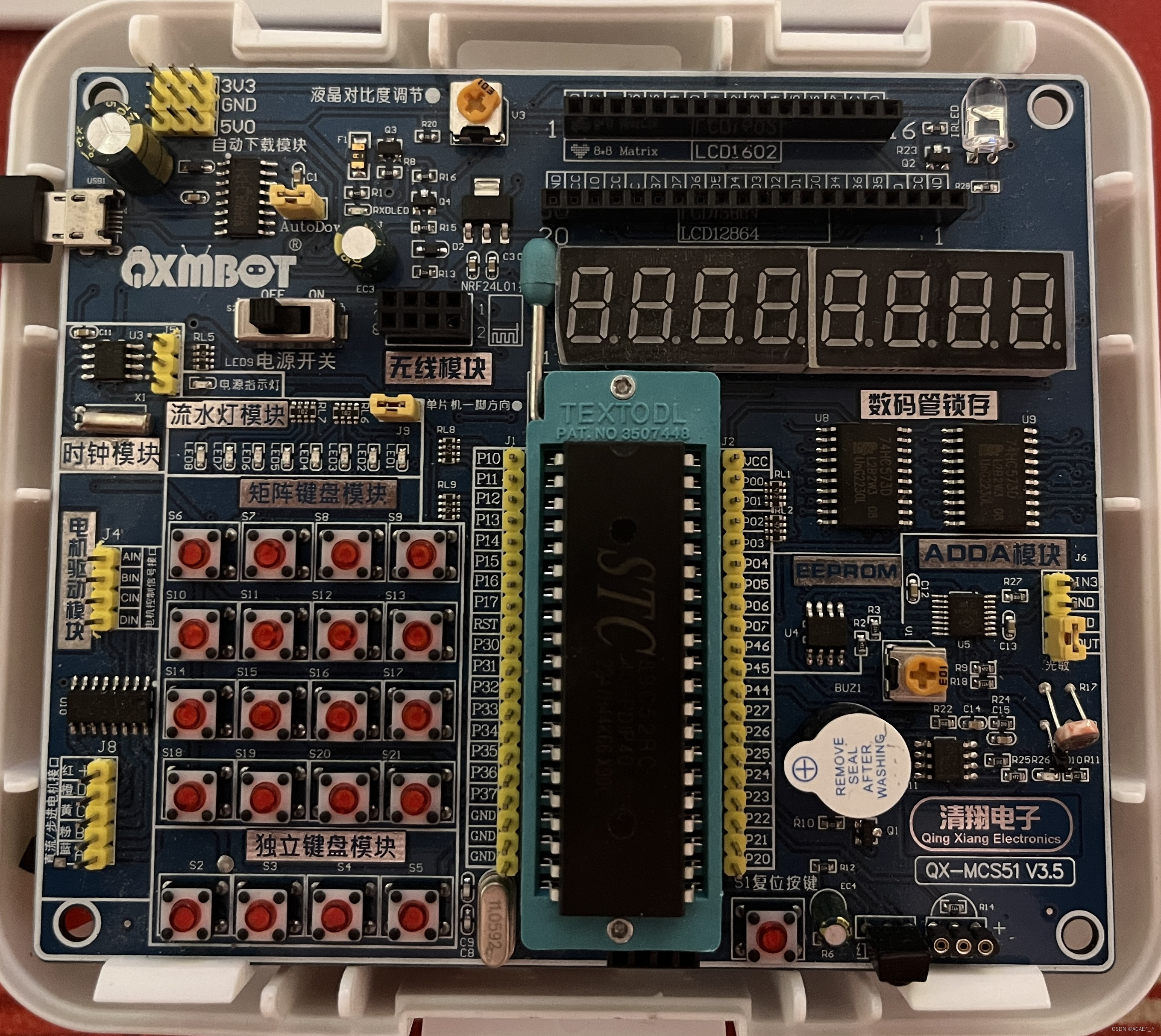
软件安装
keil5

官方网址:https://www.keil.com/
进入点击下载,选择C51.
stc-isp

官方网站:http://stcmcudata.com/
单片机命名规则

自己的

用keil5写代码
1.project --> 2.New μVision project --> 3.保存在一个文件夹里(建议一个工程对应一个文件夹)
–> 4.在search中填AT89C52(从下面找到选择也可以) --> 5.出现的框,选是和否都可以 --> 6.选择Source Group 1右键选择New Item --> 7.选择语言,起名(第一个一般叫main) --> 8.点击
从Output中勾选
–>8.编译(点左上角一个蓝色箭头的Build)
用stc-isp烧录
1.选择单片机型号(我的是STC89C52RC) --> 2.串口号可以新版本自动匹配上(没有就从自己电脑的设备管理器上看,再选择) --> 3.点打开程序文件,选择要烧录的hex文件(在Object文件夹里) --> 4.重启单片机
一.点亮LED灯

1.点亮一个LED灯
LED(发光二极管):正极引脚较长,负极引脚较小 或 灯内引脚小的为正极,大的为负极
标号102表示1K,前几位数字*10^最后一位
TTL电频标准:高电频是5V 用1表示,低电频是0V 用0表示;
上电时,单片机所有IO口默认是高电频
由LED流水灯原理图可知,P1口输出低电频时,LED就会亮;
#include <REGX52.H>  //在main函数上右键选择生成

void main()
{
	P1 = 0xFE; //0x表示十六进制 对应二进制 1111 1110
	while(1);
}
2.LED闪烁
在stc-isp中右边找到"软件延时计算器",选择对应的系统频率和想要的间隔时长以及对应的指令集
stc89系列的选择 STC-Y1

生成的代码是一个函数
因为生成的代码里有_nop_(),所以需要添加头文件 #include<INTRINS.H>
下面是一个LED以两秒为周期闪烁的代码
#include <REGX52.H>
#include <INTRINS.H>

void Delay1000ms()		//@12.000MHz
		{
			unsigned char i, j, k;

			_nop_();
			i = 8;
			j = 154;
			k = 122;
			do
			{
				do
				{
					while (--k);
				} while (--j);
			} while (--i);
		}

void main()
{
	while(1){
		P1 = 0xFE;  //灯亮
		Delay1000ms();  //等待1s
		P1 = 0xFF;  //灯灭
		Delay1000ms();  //等待1s
	}
}
3.LED流水灯
延时函数也可以生成一个单位时间的,通过循环实现各种时间的延时;
#include <REGX52.H>
#include <INTRINS.H>

void Delay1000ms()		//@12.000MHz
		{
			unsigned char i, j, k;

			_nop_();
			i = 8;
			j = 154;
			k = 122;
			do
			{
				do
				{
					while (--k);
				} while (--j);
			} while (--i);
		}

void main()
{
	while(1){
		P1 = 0xFE;
		Delay1000ms();
		P1 = 0xFD;
		Delay1000ms();
		P1 = 0xFB;
		Delay1000ms();
		P1 = 0xF7;
		Delay1000ms();
		P1 = 0xEF;
		Delay1000ms();
		P1 = 0xDF;
		Delay1000ms();
		P1 = 0xBF;
		Delay1000ms();
		P1 = 0x7F;
		Delay1000ms();
	}
}
二.用独立按键控制LED
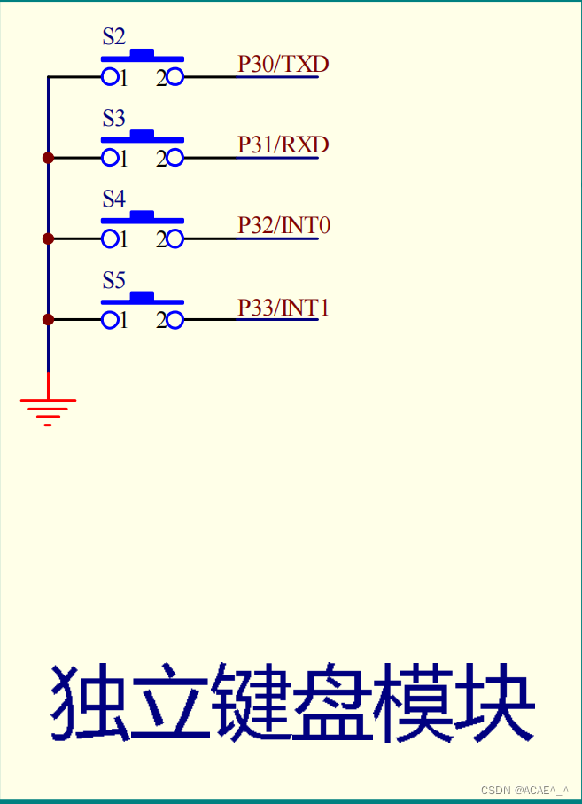
按下时接通,松开时断开
1.控制LED亮灭
用sbit关键字,可以只操作1位;只需要操作一个LED灯,不需要用P1=0xFE(操作8位)
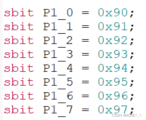
在头文件中已经定义了各个IO口,可以直接使用;
操作一位,赋值只能给0或1(零或非零数);
#include <REGX52.H>

void main()
{
	while(1){
		if(P3_0 == 0){
			P1_0=0;
		}else{
			P1_0=1;
		}
	}
}
2.控制LED状态
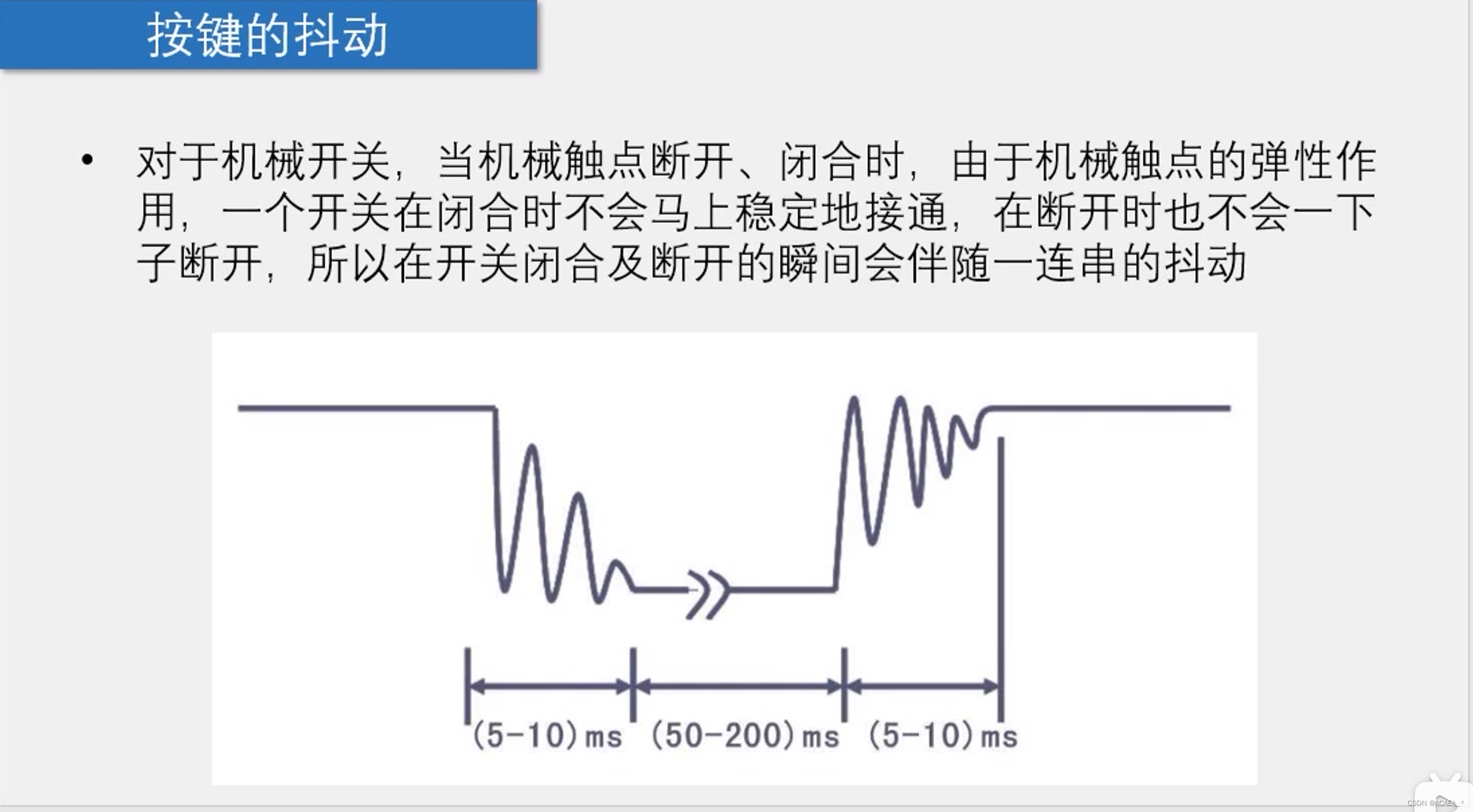
按键按下时可能会出现误操作,如按一次可能检测成按多次
所以需要按键的消抖:1.硬件;2.软件:在程序中,检测按按键时延时一段时间(如20ms)
#include <REGX52.H>

void Delay1ms(int x)		//@12.000MHz
{
	unsigned char i, j;
	for(;i>0;i--){
		i = 2;
		j = 239;
		do
		{
			while (--j);
		} while (--i);
	}
}

void main()
{
	while(1){
		if(P3_0 == 0){
			Delay1ms(20);  //消除按键按下时的抖动
			while(P3_0 == 0);  //使按键处于按下状态时困在循环里
			Delay1ms(20);  //消除按键抬起时的抖动
			P1_0=~P1_0;
		}
	}
}
3.控制LED显示二进制
#include <REGX52.H>

void Delay1ms(int x)
{
	unsigned char i, j;
	for(;x>0;x--){
		i = 2;
		j = 239;
		do
		{
			while (--j);
		} while (--i);
	}
}

void main()
{
	while(1){
		if(P3_0 == 0){
			Delay1ms(20);
			while(P3_0 == 0);
			Delay1ms(20);
			P1--;     //IO口初始都是高电频,即1111 1111
		}
	}
}

/*
也可以
void main()
{
	unsigned char LED_ = 0;  //因为char是1字节,刚好对应P2寄存器的8位IO口
		while(1){
		if(P3_0 == 0){
			Delay1ms(20);
			while(P3_0 == 0);
			Delay1ms(20);
			LED_++;
			P1 = ~LED_;
		}
	}
}
*/
4.控制LED移位
#include <REGX52.H>

void Delay1ms(int x)
{
	unsigned char i, j;
	for(;x>0;x--){
		i = 2;
		j = 239;
		do
		{
			while (--j);
		} while (--i);
	}
}

void main()
{
	unsigned char LED = 0x01;
	P1 = ~LED;
	while(1){
		if(P3_0 == 0){
			Delay1ms(20);
			while(P3_0 == 0);
			Delay1ms(20);
			LED=LED<<1;
			P1 = ~LED;
			//对处于边界时的处理,因为左移右移都会补0,对于左移为0x80,再左移会变成0x00
			if(LED == 0x00){
				LED = 0x01;
				P1 = ~LED;
			}
		}
		if(P3_1 == 0){
			Delay1ms(20);
			while(P3_1 == 0);
			Delay1ms(20);
			LED = LED>>1;
			P1 = ~LED;
			//对处于边界时的处理,因为左移右移都会补0,对于右移为0x01,再右移会变成0x00
			if(LED == 0x00){
				LED = 0x80;
				P1 = ~LED;
			}
		}
	}
}
三.数码管显示
数码管是有多个发光二极管封装在一起组成"8"字型的器件;


共阴极:二极管的所有阴极都接在一个引脚上,该引脚接GND共阳极同理,引脚接VCC.**
使数码管显示的二进制码称为段码;
若想显示数字1,**由原理图可知,dp(原理图中为h)为最高位,a为最低位,**所以段码为0000 0110

段选为(a)图中的a,b,c,d,e,f,g,h引脚,两个公共引脚(两个GND或两个VCC)为位选


上拉电阻为原理图中的RL1和RL2;
开漏状态:只能输出低电频,不能输出高电频; 加入上拉电阻后就都能输出了
1.静态
#include <REGX52.H>

/*
P2_6-->数码管段选
P2_7-->数码管位选
1.控制位选(P2_3=1),选择哪个数码管亮,则给哪个数码管的位选为0
2.控制段选
*/

void main()
{
	P2_7=1; //打开位选锁存器
	P0_0=0; //P0=0xFE; 给WE1赋0值,使得只有第一个数码管亮
	P2_7=0; //锁存位选数据

	P2_6=1; //打开段选锁存器
	P0=0x06; //输入高电频1,LED灯会亮
	P2_6=0; //锁存段选数据
	while(1){

	}

}
2.动态
#include <REGX52.H>

void Delay1ms()		//@12.000MHz
{
	unsigned char i, j;

	i = 2;
	j = 239;
	do
	{
		while (--j);
	} while (--i);
}

void main()
{
	int a[]={0x3F,0x06,0x5B,0x4F,0x66,0x6D,0x7D,0x07,0x7F,0x6F};//0,1,2,3,4,5,6,7,8,9
	int i=0;
	unsigned char LED=0x01;
	while(1){
		P2_7=1;
		P0=~LED;
		P2_7=0;

		P2_6=1;
		P0=a[i++];
		if(i==8){
			i=0;
		}
		P2_6=0;


		LED<<=1;
		if(LED==0x00){
			LED=0x01;
		}

		//下面两步操作称为"消影"
		Delay1ms();
		P0=0xFF; //清除段码
	}
}
四.程序化编程
在一个项目中
在main.c文件中
#include <REGX52.H>
#include "Delay.h"

void main()
{
	int a[]={0x3F,0x06,0x5B,0x4F,0x66,0x6D,0x7D,0x07,0x7F,0x6F};//0,1,2,3,4,5,6,7,8,9
	int i=0;
	unsigned char LED=0x01;
	while(1){
		P2_7=1;
		P0=~LED;
		P2_7=0;

		P2_6=1;
		P0=a[i++];
		if(i==8){
			i=0;
		}
		P2_6=0;


		LED<<=1;
		if(LED==0x00){
			LED=0x01;
		}

		//下面两步操作称为"消影"
		Delay1ms();
		P0=0xFF; //清除段码
	}
}
在Delay.c文件中
void Delay1ms()		//@12.000MHz
{
	unsigned char i, j;

	i = 2;
	j = 239;
	do
	{
		while (--j);
	} while (--i);
}
在Delay.h文件中
#ifndef _DELAY_H_
#define _DELAY_H_

void Delay1ms();

#endif
五.矩阵键盘


在数码管上显示矩阵键盘键码
建议:运用程序化编程
#include <REGX52.H>

void Delay1ms();
int MatrixKey();
void show(int x);
int a[] = {0x3F,0x06,0x5B,0x4F,0x66,0x6D,0x7D,0x07,0x7F,0x6F};

void main()
{

	while(1){
		int i=MatrixKey();

		if(i>=0){
			switch(i){
				case 1:show(1);break;
				case 2:show(2);break;
				case 3:show(3);break;
				case 4:show(4);break;
				case 5:show(5);break;
				case 6:show(6);break;
				case 7:show(7);break;
				case 8:show(8);break;
				case 9:show(9);break;
				case 0:show(0);break;
			}
		}
	}
}


void Delay(int x)
{
	unsigned char i, j;
	while(x--){
		i = 2;
		j = 239;
		do
		{
			while (--j);
		} while (--i);
	}
}

int MatrixKey()
{
	int i = -1;
	P3 = 0xFF;
	P3_0 = 0;
	if(P3_4 == 0){Delay(20);while(P3_4 == 0);Delay(20);i = 1;}
	if(P3_5 == 0){Delay(20);while(P3_5 == 0);Delay(20);i = 2;}
	if(P3_6 == 0){Delay(20);while(P3_6 == 0);Delay(20);i = 3;}

	P3 = 0xFF;
	P3_1 = 0;
	if(P3_4 == 0){Delay(20);while(P3_4 == 0);Delay(20);i = 4;}
	if(P3_5 == 0){Delay(20);while(P3_5 == 0);Delay(20);i = 5;}
	if(P3_6 == 0){Delay(20);while(P3_6 == 0);Delay(20);i = 6;}

	P3 = 0xFF;
	P3_2 = 0;
	if(P3_4 == 0){Delay(20);while(P3_4 == 0);Delay(20);i = 7;}
	if(P3_5 == 0){Delay(20);while(P3_5 == 0);Delay(20);i = 8;}
	if(P3_6 == 0){Delay(20);while(P3_6 == 0);Delay(20);i = 9;}

	P3 = 0xFF;
	P3_3 = 0;
	if(P3_4 == 0){Delay(20);while(P3_4 == 0);Delay(20);i = 0;}

	return i;
}

void show(int x){
	P0=0xFF;
	P2_7=1;
	P0=0xFE;
	P2_7=0;

	P2_6=1;
	P0=a[x];
	P2_6=0;
	Delay(5);
}
六.定时器


工作模式1(16位定时器/计数器)框图:

- SYSclk:系统时钟,用来产生固定频率的脉冲(晶振电路)来使后面的计数器的计数值累加.
- MCU in 12T/6T mode:分频模式,例如当晶振频率为12MHz,采用MCU in 12T mode(即12MHz÷12)时,产生的脉冲频率就是1MHz.
- T0 Pin:外部接口,当由外部接口来提供脉冲时,作计数器使用
- C/T非:配置寄存器时若其对应的控制字为1,则为Count计数器模式,为0,则为Time定时器模式
- TH0和TL0:Time High 0和Time Low 0,代表了定时器的高位和低位,后面的0表示计时器0,计数器共十六位,最大计数值为65535
- TF0:Time Flag 0,表示计时器0的标志位,当达到最大技术值后,下一次计数就会溢出,产生脉冲传送到标志位从而影响后面的Interrupt,从而申请中断
1.按键控制LED流水灯模式
Timer0函数可以使用stc-isp中的定时器计算器生成
需要选择定时器(这里是选择定时器0);定时器模式选择16位,定时器时钟选择12T(若是使用6T,则在应用界面左侧勾选"使能6T模式")
main.c文件
#include <REGX52.H>
#include <INTRINS.H>
#include "Timer0.h"
#include "Key.h"

unsigned char KeyNum,LEDMode;

void main()
{
	Timer0_Init();
	P1=0xFE;
	while(1){
		KeyNum = Key();
		if(KeyNum){
			if(KeyNum == 1){
				LEDMode++;
				if(LEDMode>=2)LEDMode = 0;
			}
		}
	}
}


void Time0_Routine() interrupt 1
{
	static unsigned int T0Count;
	TH0 = 64535/256;  //设置定时初值
	TL0 = 64535%256;  //设置定时初值
	/*或
	TL0 = 0x18;
	TH0 = 0xFC;
	*/
	T0Count++;
	if(T0Count>=500){
		T0Count = 0;
		if(LEDMode == 0)
			P1=_crol_(P1,1);
		if(LEDMode == 1)
			P1=_cror_(P1,1);
	}

}
Timer0.c文件
#include <REGX52.H>

/**
	* @brief(简介函数作用)     定时器0初始化,1毫秒@12.000MHz
	* @param(介绍函数参数)     无
	* @retval(返回值类型说明)  无
	*/
void Timer0Init(void)		//1毫秒@12.000MHz
{
	//定时器配置
	TMOD &= 0xF0;		//设置定时器模式
	TMOD |= 0x01;		//设置定时器模式
	TL0 = 0x18;		//设置定时初值
	TH0 = 0xFC;		//设置定时初值
	TF0 = 0;		//清除TF0标志
	TR0 = 1;		//定时器0开始计时

	//中断器配置
	ET0 = 1;
	EA = 1;
	PT0 = 0;
}

/*一般放在main.c文件中
定时器中断函数模板,需要时复制到main.c文件中,放在main函数下方即可
void Time0_Routine() interrupt 1
{
	static unsigned int T0Count;
	TL0 = 0x18;		//设置定时初值
	TH0 = 0xFC;		//设置定时初值
	T0Count++;
	if(T0Count>=1000){
		T0Count = 0;
	}

}
*/
Key.c文件
#include <REGX52.H>
#include "Delay.h"

/**
	* @brief  获取独立按键键码
	* @param  无
	* @retval	按下按键,返回独立按键键码 1~4,无按键按下时返回值为 0
	*/

unsigned char Key()
{
	unsigned char KeyNumber = 0;

	if(P3_0 == 0){Delay(20);while(P3_0 == 0);Delay(20);KeyNumber = 1;}
	if(P3_1 == 0){Delay(20);while(P3_1 == 0);Delay(20);KeyNumber = 2;}
	if(P3_2 == 0){Delay(20);while(P3_2 == 0);Delay(20);KeyNumber = 3;}
	if(P3_3 == 0){Delay(20);while(P3_3 == 0);Delay(20);KeyNumber = 4;}

	return KeyNumber;
}
Delay.c文件
void Delay(int x)
{
	unsigned char i, j;
	for(;x>0;x--){
		i = 2;
		j = 239;
		do
		{
			while (--j);
		} while (--i);
	}
}
在项目中加上对应的.h文件即可
2.定时器时钟
main.c文件
#include <REGX52.H>
#include "Delay.h"
#include "LED1602.h"
#include "Timer0.h"

unsigned char Sec=50,Min=59,Hour=17;

void main()
{
	LCD_Init();
	Timer0_Init();

	LCD_ShowString(1,1,"Clock:");

	while(1){
		LCD_ShowNum(2,1,Hour,2);
		LCD_ShowString(2,3,":");
		LCD_ShowNum(2,4,Min,2);
		LCD_ShowString(2,6,":");
		LCD_ShowNum(2,7,Sec,2);
	}
}

void Time0_Routine() interrupt 1
{
	static unsigned int T0Count;
	TH0 = 64535/256;
	TL0 = 64535%256;
	T0Count++;
	if(T0Count>=1000){
		T0Count = 0;
		Sec++;
		if(Sec == 60){
			Sec = 0;
			Min++;
		}
		if(Min == 60){
			Min = 0;
			Hour++;
		}
		if(Hour == 24){
			Hour = 0;
		}
	}

}
LCD1602.c文件从江协科技获得,其他文件延用上一节即可
七.串口


1.串口向电脑发送数据
main.c
#include <REGX52.H>
#include "Delay.h"
#include "UART.h"

unsigned char Sec;

void main()
{
	UART_Init();

	while(1){
		UART_SendByte(Sec++);
		Delay(1000);
	}
}
UART.c
#include <REGX52.H>

//stc-isp生成的
void UART_Init()		//4800bps@11.0592MHz
{
	PCON |= 0x80;		//使能波特率倍速位SMOD
	SCON = 0x50;		//8位数据,可变波特率

	TMOD &= 0x0F;		//清除定时器1模式位
	TMOD |= 0x20;		//设定定时器1为8位自动重装方式
	TL1 = 0xF4;		//设定定时初值
	TH1 = 0xF4;		//设定定时器重装值
	ET1 = 0;		//禁止定时器1中断
	TR1 = 1;		//启动定时器1
}

void UART_SendByte(unsigned char Byte)
{
	SBUF = Byte;
	while(TI == 0);
	TI = 0;
}
2.电脑通过串口控制LED
main.c
#include <REGX52.H>
#include "UART.h"

unsigned char Sec;

void main()
{
	UART_Init();

	while(1){

	}
}

void UART_Routine() interrupt 4
{
	if(RI == 1){
		P1 = ~SBUF;
		UART_SendByte(SBUF);
		RI = 0;
	}
}


 739
739


 被折叠的 条评论
为什么被折叠?
被折叠的 条评论
为什么被折叠?
 到【灌水乐园】发言


