


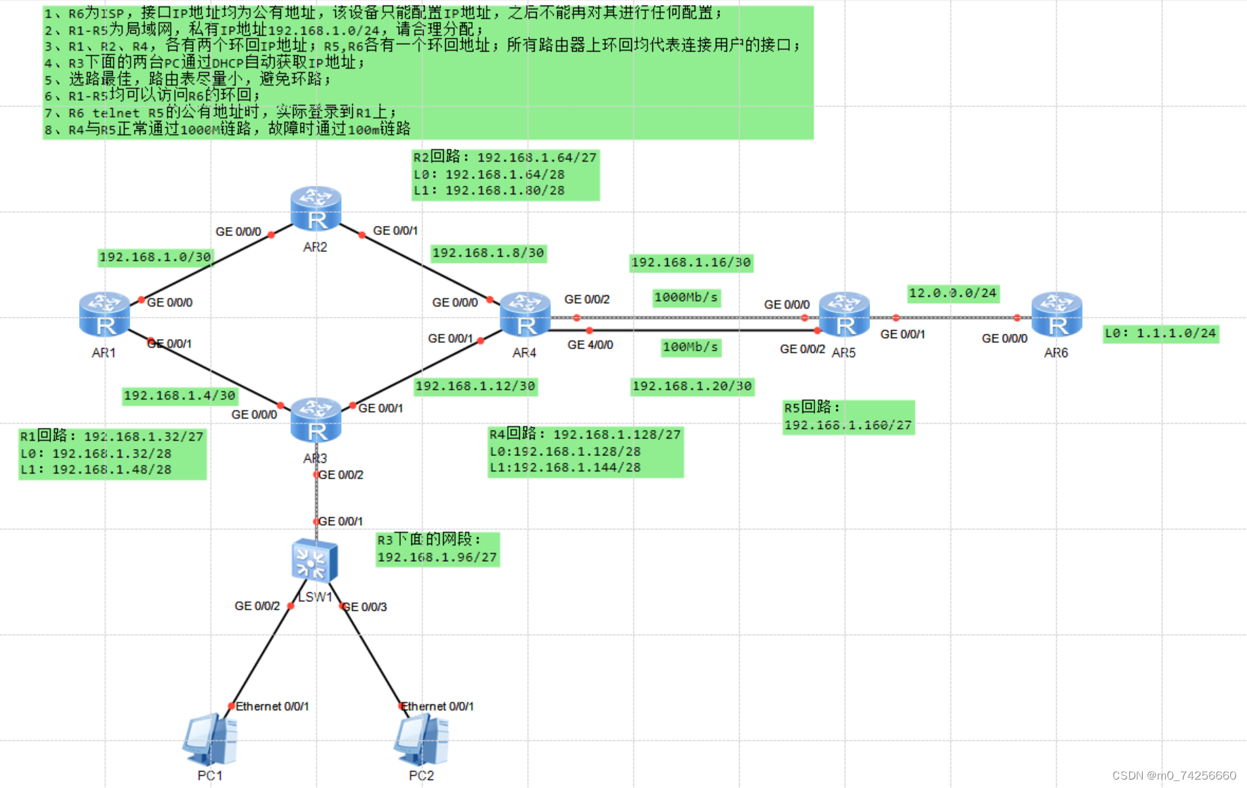
一、实验拓扑
二、实验需求
1、R6为ISP,接口IP地址均为公有地址,该设备只能配置IP地址,之后不能再对其进行任何配置;
2、R1-R5为局域网,私有IP地址192.168.1.0/24,请合理分配;
3、R1、R2、R4,各有两个环回IP地址;R5,R6各有一个环回地址;所有路由器上环回均代表连接用户的接口;
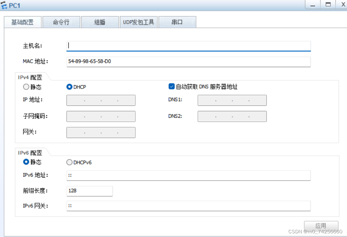
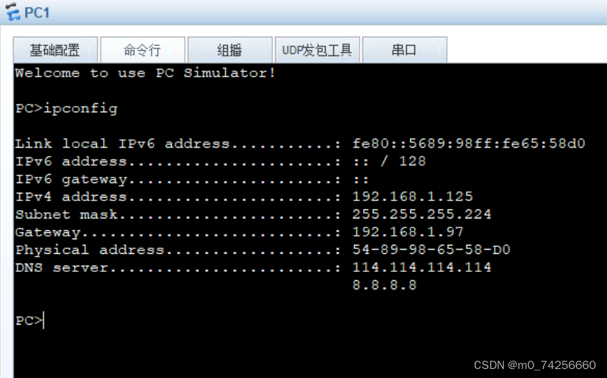
4、R3下面的两台PC通过DHCP自动获取IP地址;
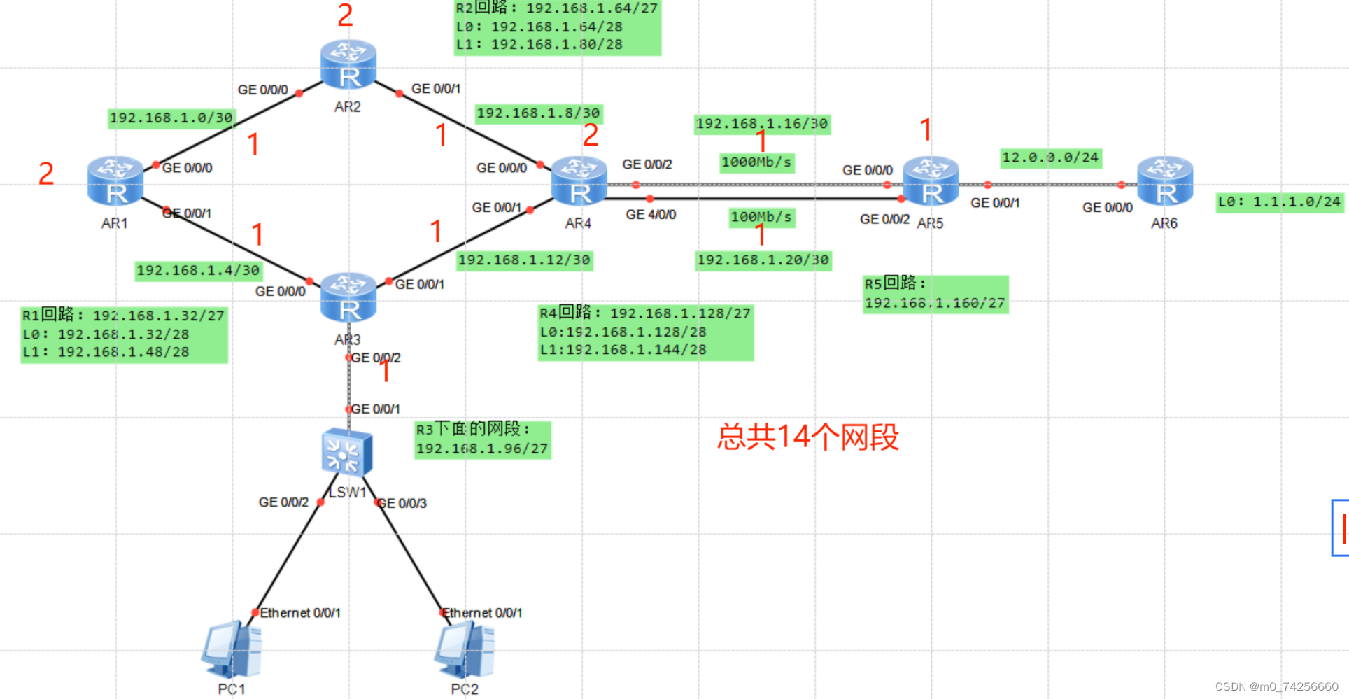
5、选路最佳,路由表尽量小,避免环路;
6、R1-R5均可以访问R6的环回;
7、R6 telnet R5的公有地址时,实际登录到R1上;
8、R4与R5正常通过1000M链路,故障时通过100m链路;
三、实验思路
1、划分IP,给设备配置IP地址
为避免浪费资源可将192.168.1.0/24划分为6个网段
(1)192.168.1.0000 0000 ---- 192.168.1.0/27 骨干链路
骨干链路有6条,将192.168.1.0/27网段划分为6个小网段
192.168.1.0000 0000 ---- 192.168.1.0/30
192.168.1.0000 0100 ---- 192.168.1.4/30
192.168.1.0000 1000 ---- 192.168.1.8/30
192.168.1.0000 1100 ---- 192.168.1.12/30
192.168.1.0001 0000 ---- 192.168.1.16/30
192.168.1.0001 0100 ---- 192.168.1.20/30
(2)192.168.1.0010 0000 ---- 192.168.1.32/27 --- R1回路
为方便汇总,可将192.168.1.32/27划分出2个小网段,分别配给两个环回口
192.168.1.0010 0000 ---- 192.168.1.32/28
192.168.1.0011 0000 ---- 192.168.1.48/28
(3)192.168.1.0100 0000---- 192.168.1.64/27 --- R2回路
为方便汇总,可将192.168.1.64/27划分出2个小网段,分别配给两个环回口
192.168.1.0100 0000 ---- 192.168.1.64/28
192.168.1.0101 0000 ---- 192.168.1.80/28
(4)192.168.1.0110 0000---- 192.168.1.96/27 --- R3
(5)192.168.1.1000 0000---- 192.168.1.128/27 --- R4回路
为方便汇总,可将192.168.1.128/27划分出2个小网段,分别配给两个环回口
192.168.1.1000 0000 ---- 192.168.1.128/28
192.168.1.1001 0000 ---- 192.168.1.144/28
(6)192.168.1.1010 0000---- 192.168.1.160/27 ---- R5回路
2、给R3配置DHCP,让R3下的两台PC通过DHCP自动获取IP地址
3、配置静态路由,实现除1.0.0.0/24外,设备互通,即私网通
4、做汇总、防环配置
5、配置缺省路由,实现其他设备到1.0.0.0/24互通;在R5上配置nat,实现全网通
6、在R1上配置telnet,通过nat server发布到R5的公网接口
7、改变路由条目优先级,实现备份
8、测试,观察1000Mb/s链路故障时,数据是否走100Mb/s链路
四、实验操作
1、配置IP地址
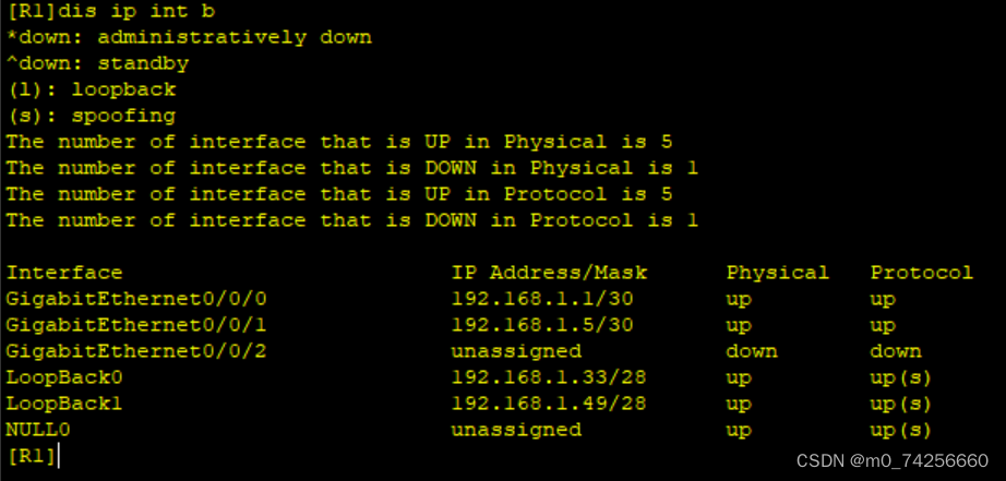
R1:
[R1]int g0/0/0
[R1-GigabitEthernet0/0/0]ip add 192.168.1.1 30
[R1]int g0/0/1
[R1-GigabitEthernet0/0/1]ip add 192.168.1.5 30
[R1]int l0
[R1-LoopBack0]ip add 192.168.1.33 28
[R1]int l1
[R1-LoopBack1]ip add 192.168.1.49 28
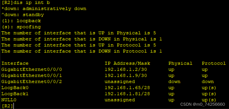
R2:
[R2]int g0/0/0
[R2-GigabitEthernet0/0/0]ip add 192.168.1.2 30
[R2]int g0/0/1
[R2-GigabitEthernet0/0/1]ip add 192.168.1.9 30
[R2]int l0
[R2-LoopBack0]ip add 192.168.1.65 28
[R2]int l1
[R2-LoopBack1]ip add 192.168.1.81 28
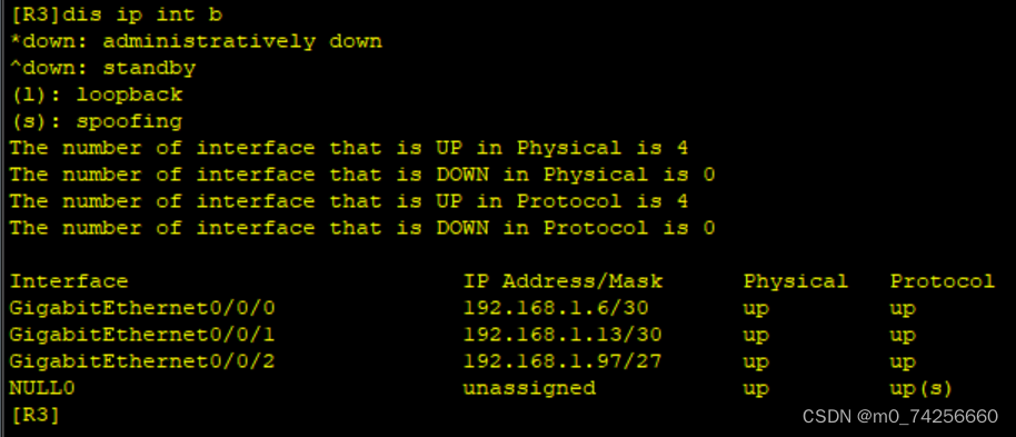
R3:
[R3]int g0/0/0
[R3-GigabitEthernet0/0/0]ip add 192.168.1.6 30
[R3]int g0/0/1
[R3-GigabitEthernet0/0/1]ip add 192.168.1.13 30
[R3]int g0/0/2
[R3-GigabitEthernet0/0/2]ip add 192.168.1.97 27
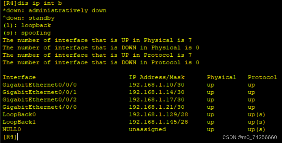
R4:
[R4]int g0/0/0
[R4-GigabitEthernet0/0/0]ip add 192.168.1.10 30
[R4]int g0/0/1
[R4-GigabitEthernet0/0/1]ip add 192.168.1.14 30
[R4]int g0/0/2
[R4-GigabitEthernet0/0/2]ip add 192.168.1.17 30
[R4]int g4/0/0
[R4-GigabitEthernet4/0/0]ip add 192.168.1.21 30
[R4]int l0
[R4-LoopBack0]ip add 192.168.1.129 28
[R4]int l1
[R4-LoopBack1]ip add 192.168.1.145 28
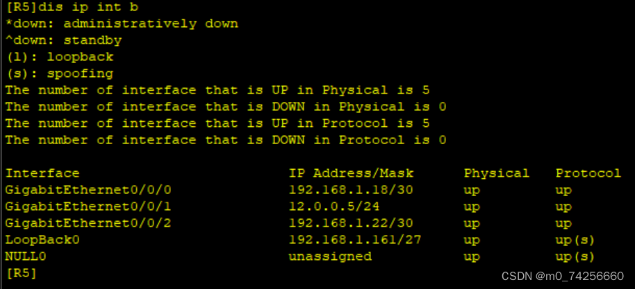
R5:
[R5]int g0/0/0
[R5-GigabitEthernet0/0/0]ip add 192.168.1.18 30
[R5]int g0/0/1
[R5-GigabitEthernet0/0/1]ip add 12.0.0.5 24
[R5]int g0/0/2
[R5-GigabitEthernet0/0/2]ip add 192.168.1.22 30
[R5]int l0
[R5-LoopBack0]ip add 192.168.1.161 27
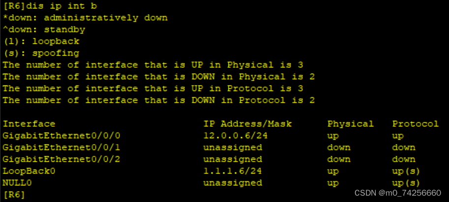
R6:
[R6]int g0/0/0
[R6-GigabitEthernet0/0/0]ip add 12.0.0.6 24
[R6]int l0
[R6-LoopBack0]ip add 1.1.1.6 24
2、配置DHCP,使R3下面的两台PC通过DHCP自动获取IP地址
[R3]dhcp enable
[R3]ip pool aa
[R3-ip-pool-aa]network 192.168.1.96 mask 27
[R3-ip-pool-aa]gateway-list 192.168.1.97
[R3-ip-pool-aa]dns-list 114.114.114.114 8.8.8.8
[R3]int g0/0/2
[R3-GigabitEthernet0/0/2]dhcp select global
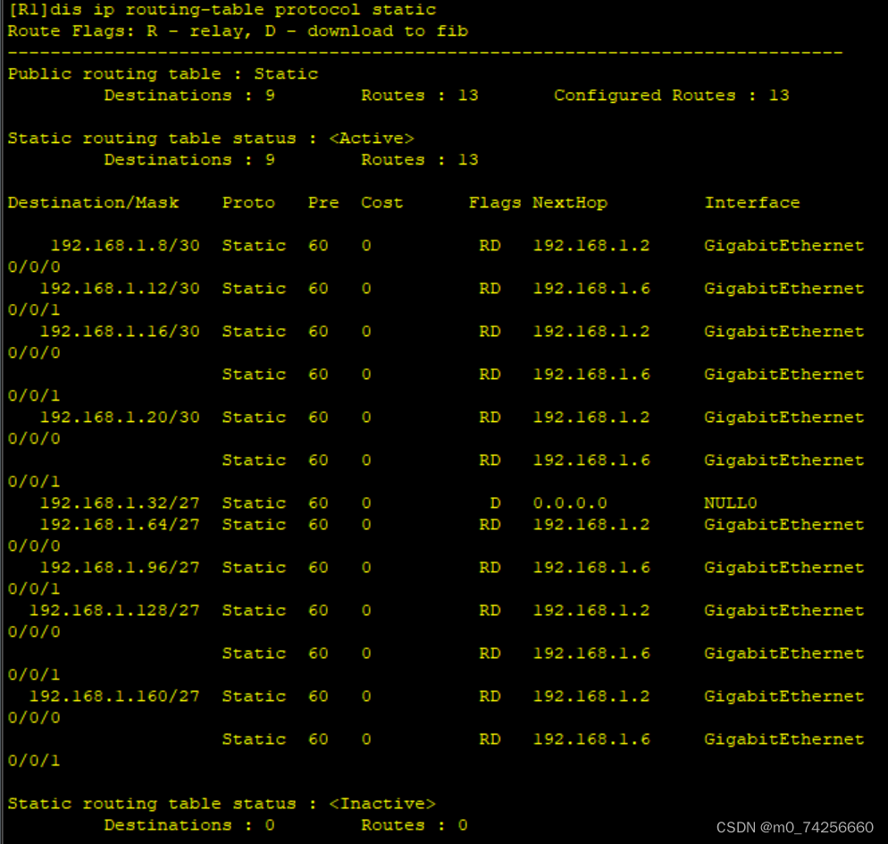
3、配置静态路由 实现私网全通
R1:
[R1]ip route-static 192.168.1.64 27 192.168.1.2
[R1]ip route-static 192.168.1.8 30 192.168.1.2
[R1]ip route-static 192.168.1.128 27 192.168.1.2
[R1]ip route-static 192.168.1.128 27 192.168.1.6
[R1]ip route-static 192.168.1.16 30 192.168.1.2
[R1]ip route-static 192.168.1.16 30 192.168.1.6
[R1]ip route-static 192.168.1.160 27 192.168.1.2
[R1]ip route-static 192.168.1.160 27 192.168.1.6
[R1]ip route-static 192.168.1.20 30 192.168.1.2
[R1]ip route-static 192.168.1.20 30 192.168.1.6
[R1]ip route-static 192.168.1.12 30 192.168.1.6
[R1]ip route-static 192.168.1.96 27 192.168.1.6
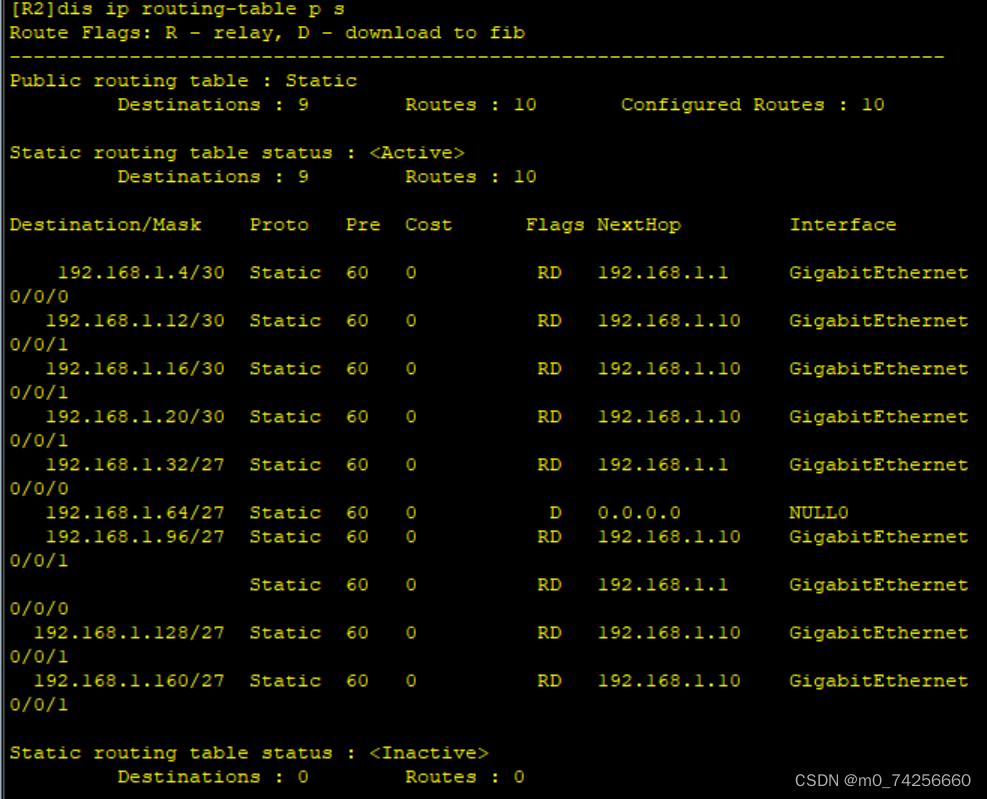
R2:
[R2]ip route-static 192.168.1.128 27 192.168.1.10
[R2]ip route-static 192.168.1.16 30 192.168.1.10
[R2]ip route-static 192.168.1.160 27 192.168.1.10
[R2]ip route-static 192.168.1.20 30 192.168.1.10
[R2]ip route-static 192.168.1.12 30 192.168.1.10
[R2]ip route-static 192.168.1.96 27 192.168.1.10
[R2]ip route-static 192.168.1.96 27 192.168.1.1
[R2]ip route-static 192.168.1.4 30 192.168.1.1
[R2]ip route-static 192.168.1.32 27 192.168.1.1
R3:
[R3]ip route-static 192.168.1.32 27 192.168.1.5
[R3]ip route-static 192.168.1.0 30 192.168.1.5
[R3]ip route-static 192.168.1.64 27 192.168.1.5
[R3]ip route-static 192.168.1.64 27 192.168.1.14
[R3]ip route-static 192.168.1.8 30 192.168.1.14
[R3]ip route-static 192.168.1.128 27 192.168.1.14
[R3]ip route-static 192.168.1.16 30 192.168.1.14
[R3]ip route-static 192.168.1.160 27 192.168.1.14
[R3]ip route-static 192.168.1.20 30 192.168.1.14
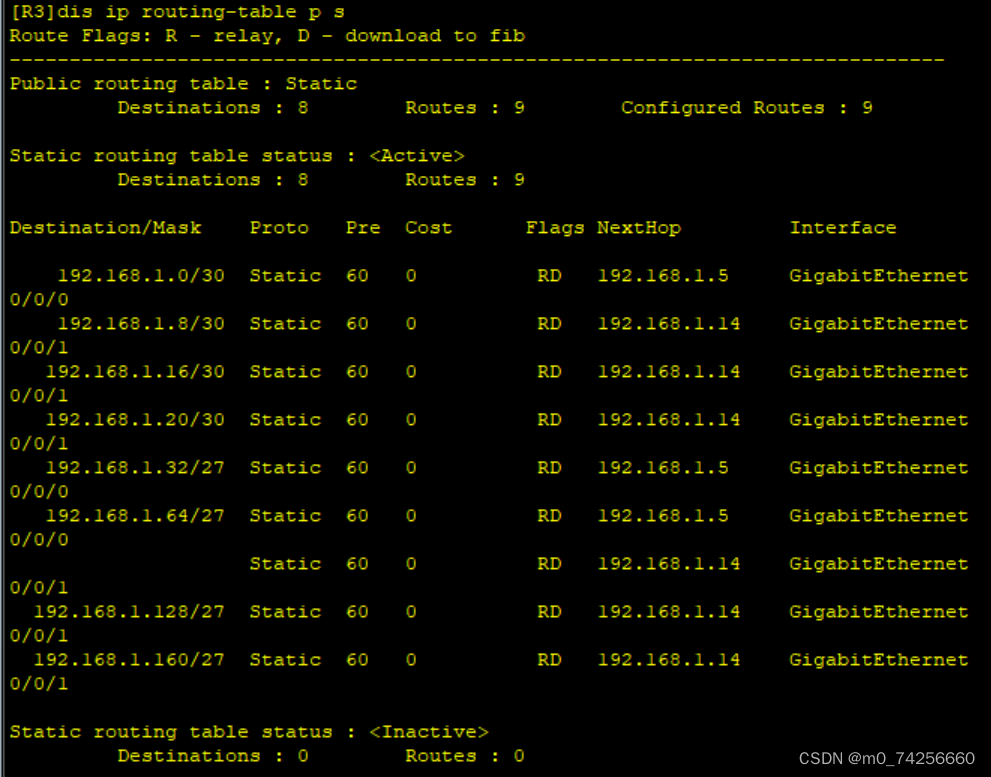
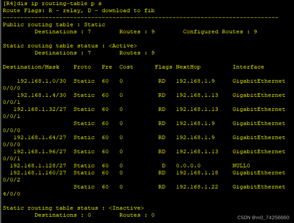
R4:
[R4]ip route-static 192.168.1.96 27 192.168.1.13
[R4]ip route-static 192.168.1.4 30 192.168.1.13
[R4]ip route-static 192.168.1.32 27 192.168.1.13
[R4]ip route-static 192.168.1.32 27 192.168.1.9
[R4]ip route-static 192.168.1.0 30 192.168.1.9
[R4]ip route-static 192.168.1.64 27 192.168.1.9
[R4]ip route-static 192.168.1.160 27 192.168.1.18
[R4]ip route-static 192.168.1.160 27 192.168.1.22
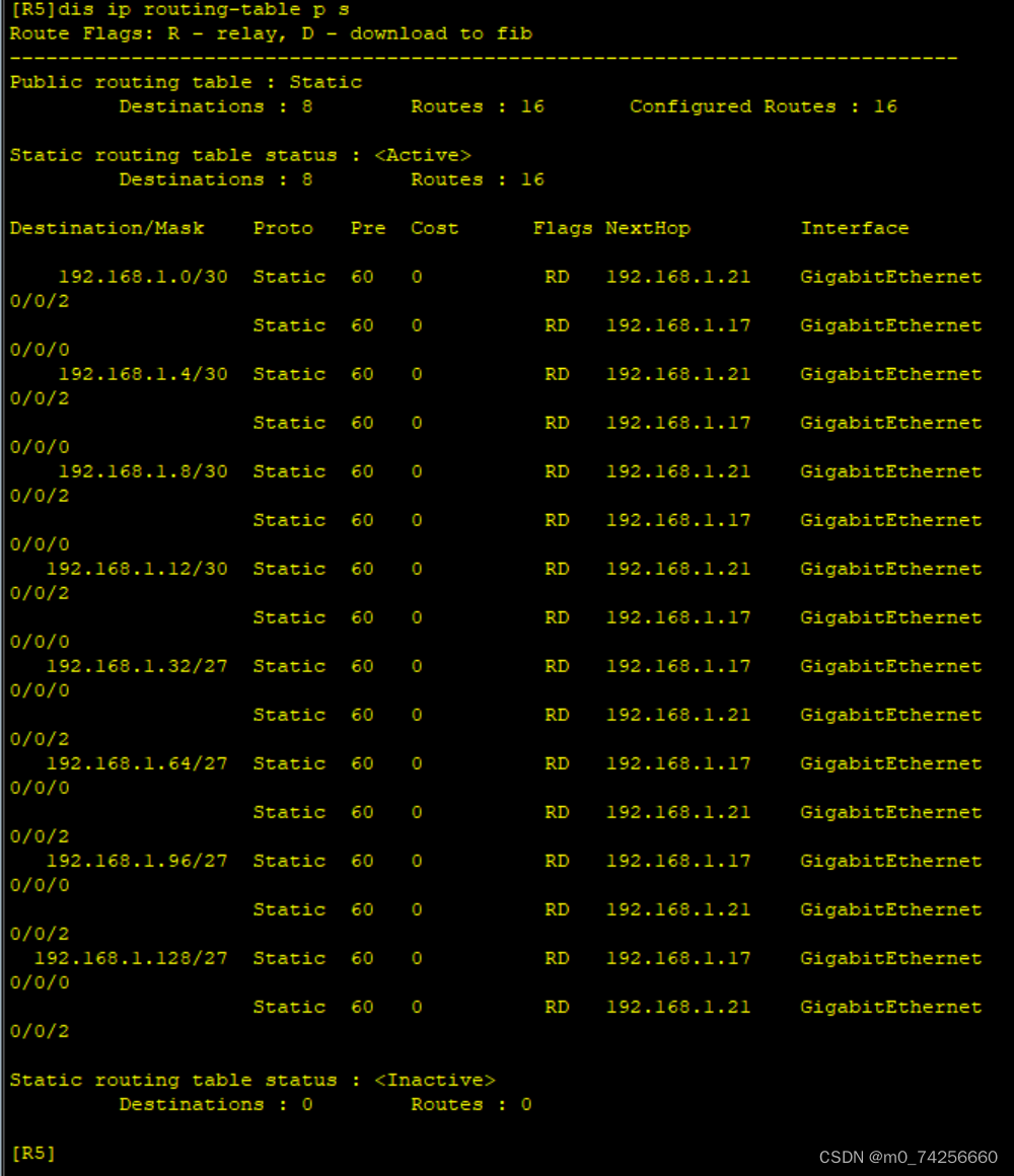
R5:
[R5]ip route-static 192.168.1.128 27 192.168.1.17
[R5]ip route-static 192.168.1.128 27 192.168.1.21
[R5]ip route-static 192.168.1.12 30 192.168.1.21
[R5]ip route-static 192.168.1.12 30 192.168.1.17
[R5]ip route-static 192.168.1.96 27 192.168.1.17
[R5]ip route-static 192.168.1.96 27 192.168.1.21
[R5]ip route-static 192.168.1.4 30 192.168.1.21
[R5]ip route-static 192.168.1.4 30 192.168.1.17
[R5]ip route-static 192.168.1.32 27 192.168.1.17
[R5]ip route-static 192.168.1.32 27 192.168.1.21
[R5]ip route-static 192.168.1.0 30 192.168.1.21
[R5]ip route-static 192.168.1.0 30 192.168.1.17
[R5]ip route-static 192.168.1.64 27 192.168.1.17
[R5]ip route-static 192.168.1.64 27 192.168.1.21
[R5]ip route-static 192.168.1.8 30 192.168.1.21
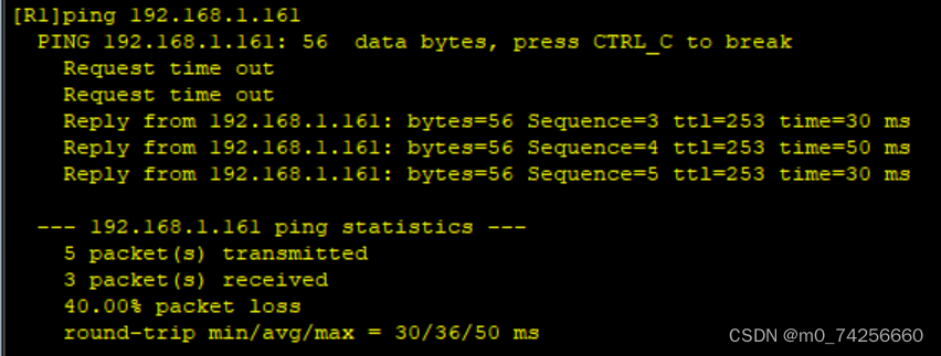
[R5]ip route-static 192.168.1.8 30 192.168.1.1
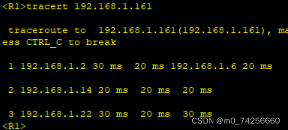
测试:192.168.1.1 ping 192.168.1.161
4、配置缺省路由 实现外网通
[R5]ip route-static 0.0.0.0 0 12.0.0.6
测试:R5 ping R6
5、做防环配置
[R1]ip route-static 192.168.1.32 27 NULL 0
[R2]ip route-static 192.168.1.64 27 NULL 0
[R4]ip route-static 192.168.1.128 27 NULL 0
6、nat配置
[R5]acl 2000
[R5-acl-basic-2000]rule permit source 192.168.1.0 0.0.0.255
[R5]int g0/0/1
[R5-GigabitEthernet0/0/1]nat outbound 2000
7、配置缺省 实现全网通
[R1]ip route-static 0.0.0.0 0 192.168.1.2
[R1]ip route-static 0.0.0.0 0 192.168.1.6
[R2]ip route-static 0.0.0.0 0 192.168.1.10
[R3]ip route-static 0.0.0.0 0 192.168.1.14
[R4]ip route-static 0.0.0.0 0 192.168.1.18
[R4]ip route-static 0.0.0.0 0 192.168.1.22
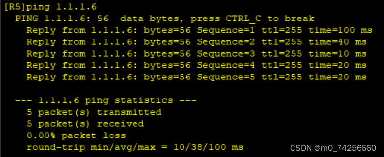
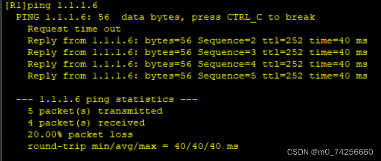
测试R1 ping R6
8、配置远程登录使R6 telnet R5的公有地址时,实际登录到R1上
[R1]aaa
[R1-aaa]local-user gujiangshan password cipher gjs12345 privilege level 15
[R1-aaa]local-user gujiangshan service-type telnet
[R1]user-interface vty 0 4
[R1-ui-vty0-4]authentication-mode aaa
[R5]int g0/0/1
[R5-GigabitEthernet0/0/1]nat server protocol tcp global current-interface 23 ins
ide 192.168.1.1 23
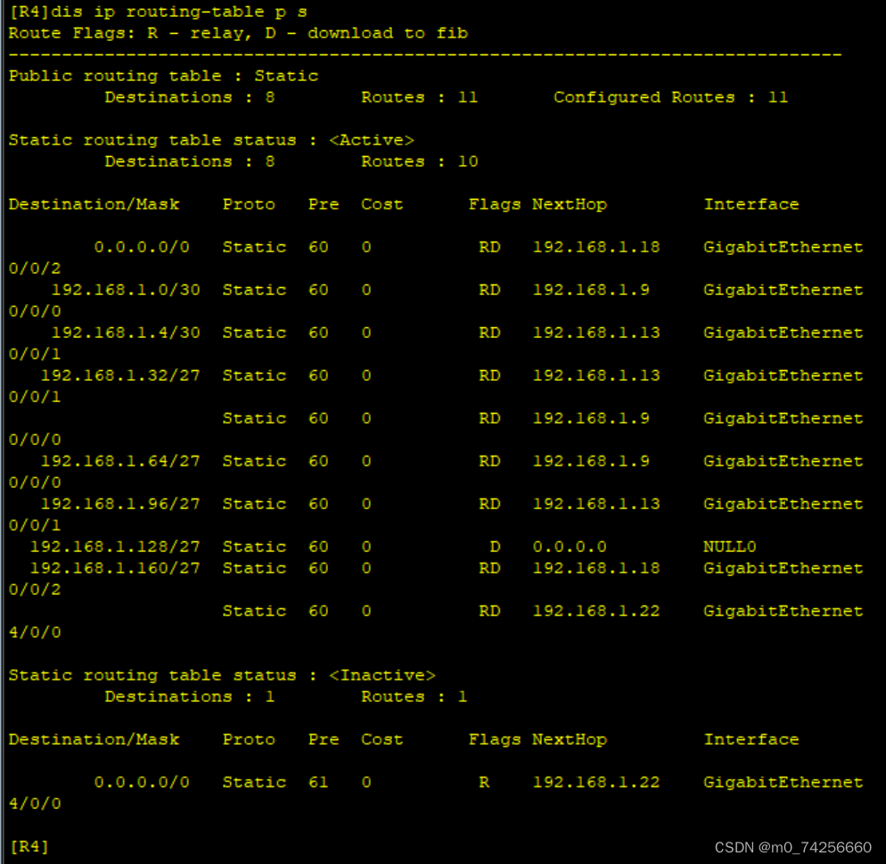
9、修改优先级使R4与R5正常通过1000M链路,故障时通过100m链路
[R4]ip route-static 0.0.0.0 0 192.168.1.22 preference 61
[R5]ip route-static 192.168.1.0 30 192.168.1.21 pre 61
[R5]ip route-static 192.168.1.4 30 192.168.1.21 pre 61
[R5]ip route-static 192.168.1.8 30 192.168.1.21 pre 61
[R5]ip route-static 192.168.1.12 30 192.168.1.21 pre 61
[R5]ip route-static 192.168.1.32 27 192.168.1.21 pre 61
[R5]ip route-static 192.168.1.64 27 192.168.1.21 pre 61
[R5]ip route-static 192.168.1.96 27 192.168.1.21 pre 61
[R5]ip route-static 192.168.1.128 27 192.168.1.21 pre 61
若还有等价路径可关闭接口查看
[R4]int g0/0/2
[R4-GigabitEthernet0/0/2]shutdown


 168
168


 被折叠的 条评论
为什么被折叠?
被折叠的 条评论
为什么被折叠?
 到【灌水乐园】发言


