


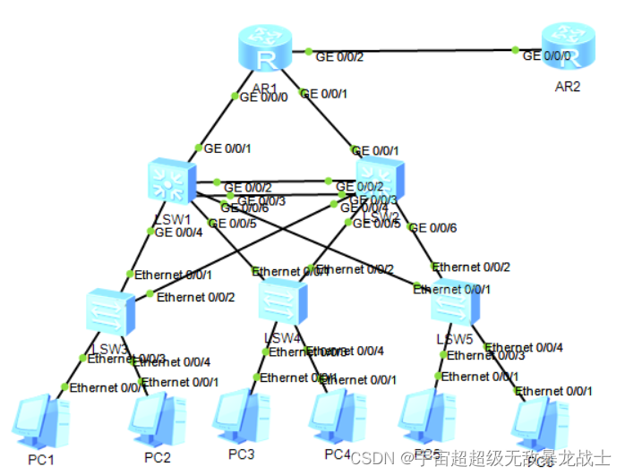
一、实验拓扑图
二、地址划分
R1:
1.1.1.1/32——环回地址
12.1.1.1/24
23.1.1.1/24
34.1.1.1/24
R2:
2.2.2.2/32——环回地址
12.1.1.2/24
三、具体配置
1、IP地址配置
R1:
[R1]int g0/0/2
[R1-GigabitEthernet0/0/2]ip add 12.1.1.1 24
[R1-GigabitEthernet0/0/2]int g0/0/0
[R1-GigabitEthernet0/0/0]ip add 23.1.1.1 24
[R1-GigabitEthernet0/0/0]int g0/0/1
[R1-GigabitEthernet0/0/1]ip add 34.1.1.1 24
[R1]int LoopBack 0
[R1-LoopBack0]ip add 1.1.1.1 32
R2:
[R2]int g0/0/0
[R2-GigabitEthernet0/0/0]ip add 12.1.1.2 24
[R2]int LoopBack 0
[R2-LoopBack0]ip add 2.2.2.2 32
2、划分vlan
SW1:
[SW1]interface Vlanif 1
[SW1-Vlanif1]ip add 23.1.1.2 24
SW2:
[SW2]interface Vlanif 1
[SW2-Vlanif1]ip add 34.1.1.2 24
3、SW1和SW2之间接口汇聚
SW1:
[SW1]interface Eth-Trunk 1
[SW1-Eth-Trunk1]q
[SW1]int g0/0/2
[SW1-GigabitEthernet0/0/2]eth-trunk 1
[SW1]int g0/0/3
[SW1-GigabitEthernet0/0/3]eth-trunk 1
[SW1]int g0/0/7
[SW1-GigabitEthernet0/0/3]eth-trunk 1
[SW1]interface Eth-Trunk 1
[SW1-Eth-Trunk1]port link-type trunk
[SW1-Eth-Trunk1]port trunk allow-pass vlan all
SW2:
[SW2]interface Eth-Trunk 1
[SW2-Eth-Trunk1]q
[SW2]int g0/0/2
[SW2-GigabitEthernet0/0/2]eth-trunk 1
[SW2-GigabitEthernet0/0/2]int g0/0/3
[SW2-GigabitEthernet0/0/3]eth-trunk 1
[SW2-GigabitEthernet0/0/3]int g0/0/7
[SW2-GigabitEthernet0/0/7]eth-trunk 1
[SW2]interface Eth-Trunk 1
[SW2-Eth-Trunk1]port link-type trunk
[SW2-Eth-Trunk1]port trunk allow-pass vlan all
4、划分vlan区域
vlan2:
SW1:
[SW1]interface g0/0/4
[SW1-GigabitEthernet0/0/4]port link-type access
[SW1-GigabitEthernet0/0/4]port default vlan 2
SW2:
[SW2]int g0/0/4
[SW2-GigabitEthernet0/0/4]port link-type access
[SW2-GigabitEthernet0/0/4]port default vlan 2
SW3:
[SW3]vlan 2
[SW3-vlan2]q
[SW3]port-group 1
[SW3-port-group-1]group-member e0/0/1 to e0/0/4
[SW3-port-group-1]port link-type access
[SW3-port-group-1]port default vlan 2
vlan3:
SW1:
[SW1]interface g0/0/5
[SW1-GigabitEthernet0/0/5]port link-type access
[SW1-GigabitEthernet0/0/5]port default vlan 3
SW2:
[SW2]interface g0/0/5
[SW2-GigabitEthernet0/0/5]port link-type access
[SW2-GigabitEthernet0/0/5]port default vlan 3
SW4:
[SW4]vlan 3
[SW4-vlan3]q
[SW4]port-group 1
[SW4-port-group-1]group-member e0/0/1 to e0/0/4
[SW4-port-group-1]port link-type access
[SW4-port-group-1]port default vlan 3
vlan3、4:
SW1:
[SW1]interface g0/0/6
[SW1-GigabitEthernet0/0/6]port link-type trunk
[SW1-GigabitEthernet0/0/6]port trunk allow-pass vlan all
SW2:
[SW2]interface g0/0/6
[SW2-GigabitEthernet0/0/6]port link-type trunk
[SW2-GigabitEthernet0/0/6]port trunk allow-pass vlan all
SW5:
[SW5]interface e0/0/1
[SW5-Ethernet0/0/1]port link-type access
[SW5-Ethernet0/0/1]port link-type trunk
[SW5-Ethernet0/0/1]port trunk allow-pass vlan all
[SW5-Ethernet0/0/1]int e0/0/2
[SW5-Ethernet0/0/2]port link-type trunk
[SW5-Ethernet0/0/2]port trunk allow-pass vlan all
[SW5-Ethernet0/0/2]int e0/0/3
[SW5-Ethernet0/0/3]port link-type access
[SW5-Ethernet0/0/3]port default vlan 2
[SW5-Ethernet0/0/3]int e0/0/4
[SW5-Ethernet0/0/4]port link-type access
[SW5-Ethernet0/0/4]port default vlan 3
5、MSTP协议生成树
SW1:
[SW1]stp mode mstp
[SW1]stp region-configuration
[SW1-mst-region]region-name a
[SW1-mst-region]instance 1 vlan 2
[SW1-mst-region]instance 2 vlan 3
[SW1-mst-region]active region-configuration
[SW1]stp instance 1 root primary
[SW1]stp instance 2 root secondary
SW2:
[SW2]stp mode mstp
[SW2]stp region-configuration
[SW2-mst-region]region-name a
[SW2-mst-region]instance 1 vlan 2
[SW2-mst-region]instance 2 vlan 3
[SW2-mst-region]active region-configuration
[SW2]stp instance 1 root secondary
[SW2]stp instance 2 root primary
6、宣告OSPF
R1:
[R1]ospf 1 router-id 1.1.1.1
[R1-ospf-1]area 0
[R1-ospf-1-area-0.0.0.0]network 34.1.1.1 0.0.0.0
[R1-ospf-1-area-0.0.0.0]network 1.1.1.1 0.0.0.0
[R1-ospf-1]default-route-advertise
[R1]ip route-static 0.0.0.0 0 12.1.1.2
SW1:
[SW1]ospf 1 router-id 2.2.2.2
[SW1-ospf-1]area 0
[SW1-ospf-1-area-0.0.0.0]network 0.0.0.0 255.255.255.255
SW2:
[SW2]ospf 1 router-id 3.3.3.3
[SW2-ospf-1]area 0
[SW2-ospf-1-area-0.0.0.0]network 0.0.0.0 255.255.255.255
7、管理vlan
SW1:
[SW1]interface Vlanif 2
[SW1-Vlanif2]ip address 192.168.1.1 24
[SW1]interface Vlanif 3
[SW1-Vlanif2]ip address 172.16.1.1 24
SW2:
[SW2]interface Vlanif 2
[SW2-Vlanif2]ip address 192.168.1.2 24
[SW2]interface Vlanif 3
[SW2-Vlanif2]ip address 172.16.1.2 24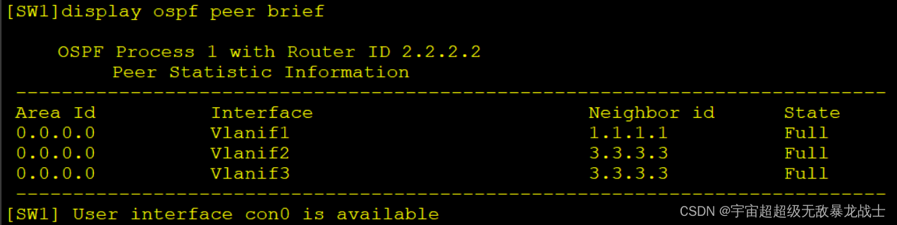
8、配置VRRP协议(在汇聚层)
SW1:
[SW1]interface Vlanif 2
[SW1-Vlanif2]vrrp vrid 1 virtual-ip 192.168.1.1
[SW1-Vlanif2]ip address 192.168.1.1 24
[SW1-Vlanif2]vrrp vrid 1 priority 120
[SW1-Vlanif2]vrrp vrid 1 preempt-mode timer delay 20
[SW1]interface Vlanif 3
[SW1-Vlanif3]vrrp vrid 2 virtual-ip 172.16.1.2
SW2:
[SW2]interface Vlanif 2
[SW2-Vlanif2]vrrp vrid 1 virtual-ip 192.168.1.1
[SW2]interface Vlanif 3
[SW2-Vlanif3]vrrp vrid 2 virtual-ip 172.16.1.2
[SW2-Vlanif3]vrrp vrid 2 priority 120
[SW2-Vlanif3]vrrp vrid 2 preempt-mode timer delay 20
9、DHCP池塘配置
SW1:
[SW1]ip pool 1
[SW1-ip-pool-1]network 192.168.1.0 mask 24
[SW1-ip-pool-1]gateway-list 192.168.1.1
[SW1-ip-pool-1]dns-list 8.8.8.8
[SW1]interface Vlanif 2
[SW1-Vlanif2]dhcp select global
[SW1]ip pool 2
[SW1-ip-pool-2]network 172.16.1.0 mask 24
[SW1-ip-pool-2]gateway-list 172.16.1.2
[SW1-ip-pool-2]dns-list 8.8.8.8
[SW1]interface Vlanif 3
[SW1-Vlanif3]dhcp select global
SW2:
[SW2]ip pool 1
[SW2-ip-pool-1]network 192.168.1.0 mask 24
[SW2-ip-pool-1]gateway-list 192.168.1.1
[SW2-ip-pool-1]dns-list 8.8.8.8
[SW2]interface Vlanif 2
[SW2-Vlanif2]dhcp select global
[SW2]ip pool 3
[SW2-ip-pool-3]network 172.16.1.0 mask 24
[SW2-ip-pool-3]gateway-list 172.16.1.2
[SW2-ip-pool-3]dns-list 8.8.8.8
[SW2]interface Vlanif 3
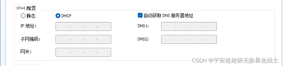
[SW2-Vlanif3]dhcp select global 10、开启各PC的DHCP服务
11、配置NAT可以访问外网
[R1]acl 2000
[R1-acl-basic-2000]rule permit source any
[R1]interface g0/0/2
[R1-GigabitEthernet0/0/2]nat outbound 2000
三、实验结果
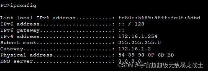
1、PC自动配置地址
2、访问外网
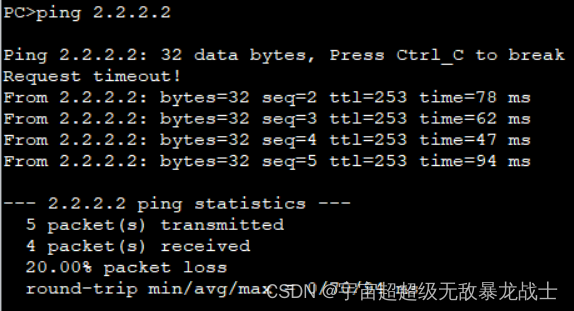
实验完成!


 266
266


 被折叠的 条评论
为什么被折叠?
被折叠的 条评论
为什么被折叠?
 到【灌水乐园】发言


