


Chapter 2: Architecture — Private 5G: A Systems Approach Version 1.1-dev documentation
This chapter identifies the main architectural components of the mobile cellular network. We need to introduce some terminology to do this, which can be confusing for those whose networking background comes from the Internet. This is partly because some of what needs to happen in a mobile network, such as keeping track of which base station is serving a given mobile device, doesn’t really have a parallel in fixed networks. On top of that, the terminology came out of the 3GPP standardization process, which was historically concerned with telephony and almost completely disconnected from the IETF and other Internet-related efforts. To further confuse matters, 3GPP terminology often changes with each generation (e.g., a base station is called eNB in 4G and gNB in 5G). We address situations like this by using generic terminology (e.g., base station), and referencing the 3GPP-specific counterpart only when the distinction is helpful. This example is only the tip of the terminology iceberg. Marcin Dryjanski’s blog post gives a broader perspective on the complexity of terminology in 5G.
Further Reading
Marcin Dryjanski. LTE and 5G Differences: System Complexity. July 2018.
2.1 Overview
The mobile cellular network provides wireless connectivity to devices that are (potentially) on the move. These devices, which are known as User Equipment (UE), have traditionally corresponded to mobile phones and tablets, but increasingly include cars, drones, industrial and agricultural machines, robots, home appliances, medical devices, and so on. In some cases, the UEs may be devices that do not move, e.g., router interfaces using cellular connectivity to provide broadband access to remote dwellings.
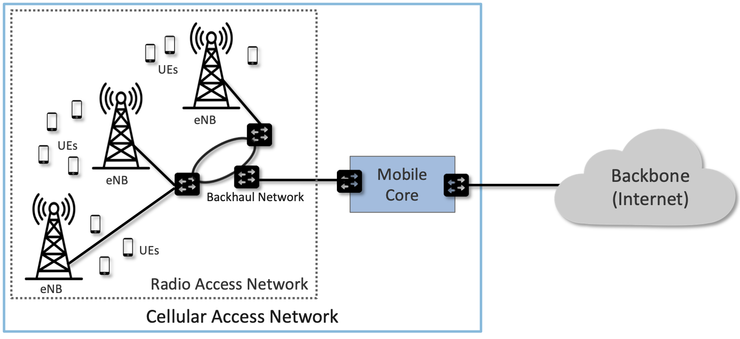
Figure 3. Mobile cellular networks consist of a Radio Access Network (RAN) and a Mobile Core.
As shown in Figure 3, the mobile cellular network consists of two main subsystems: the Radio Access Network (RAN) and the Mobile Core. The RAN manages the radio resources (i.e., spectrum), making sure it is used efficiently and meets the quality of service (QoS) requirements of every user. It corresponds to a distributed collection of base stations. As noted above, these are cryptically named eNodeB or eNB (which is short for evolved Node B) in 4G. In 5G, base stations are known as gNB, where the “g” stands for next Generation.
The Mobile Core is a bundle of functionality (conventionally packaged as one or more devices) that serves several purposes.
-
Authenticates devices prior to attaching them to the network
-
Provides Internet (IP) connectivity for both data and voice services.
-
Ensures this connectivity fulfills the promised QoS requirements.
-
Tracks user mobility to ensure uninterrupted service.
-
Tracks subscriber usage for billing and charging.
For readers familiar with the Internet architecture and Wi-Fi as a common access technology, some of these functions might look a bit surprising. For example, Wi-Fi, like most of the Internet, normally provides a best-effort service, whereas cellular networks often aim to deliver some sort of QoS guarantee. Tracking subscribers for both mobility and billing are also not the sort of things we tend to think about in the Internet, but they are considered important functions for cellular networks. The reasons for these differences are numerous, including the typically large costs of acquiring cellular spectrum and maintaining the infrastructure to use it such as radio towers. With that large investment, there is a desire to recoup costs by charging subscribers, which in turn leads to making some sort of service guarantees to those subscribers to justify the cost. There is also a need to maximize the efficiency of spectrum usage. Much of the complexity of the mobile core follows from these requirements being imposed by service providers. Even when we get to enterprises running their own 5G networks, they still need to manage the usage of spectrum to obtain the benefits of 5G over Wi-Fi, such as more predictable control over latency and bandwidth.
Note that Mobile Core is another example of a generic term. In 4G it was called the Evolved Packet Core (EPC) and in 5G it is called the 5G Core (5GC). Moreover, even though the word “Core” is in its name, the Mobile Core runs near the edge of the network, effectively providing a bridge between the RAN in some geographic area and the greater IP-based Internet. 3GPP provides significant flexibility in how the Mobile Core is geographically deployed, ranging from minimal deployments (the RAN and the mobile core can be co-located) to areas that are hundreds of kilometers wide. A common model is that an instantiation of the Mobile Core serves a metropolitan area. The corresponding RAN would then span several dozens (or even hundreds) of cell towers in that geographic area.
Taking a closer look at Figure 3, we see that a Backhaul Network interconnects the base stations that implement the RAN with the Mobile Core. This network is typically wired, may or may not have the ring topology shown in the figure, and is often constructed from commodity components found elsewhere in the Internet. For example, the Passive Optical Network (PON) that implements Fiber-to-the-Home is a prime candidate for implementing the RAN backhaul, with the RAN effectively running as an overlay on top of whatever technology is used. Switched ethernet, such as you might find in an enterprise, is another suitable choice. The backhaul network is obviously a necessary part of the RAN, but it is an implementation choice and not prescribed by the 3GPP standard.
Although 3GPP specifies all the elements that implement the RAN and Mobile Core in an open standard—including sub-layers we have not yet introduced—network operators have historically bought proprietary implementations of each subsystem from a single vendor. This lack of an open source implementation contributes to the perceived “opaqueness” of the mobile cellular network in general, and the RAN in particular. And while it is true that base stations contain sophisticated algorithms for scheduling transmission on the radio spectrum—algorithms that are considered valuable intellectual property of the equipment vendors—there is significant opportunity to open and disaggregate both the RAN and the Mobile Core. This book gives a recipe for how to do exactly that.
Before getting to those details, we have three more architectural concepts to introduce. First, Figure 4 redraws components from Figure 3 to highlight the fact that a base station has an analog component (depicted by an antenna) and a digital component (depicted by a processor pair). This book mostly focuses on the latter, but we introduce enough information about the over-the-air radio transmission to appreciate its impact on the overall architecture.
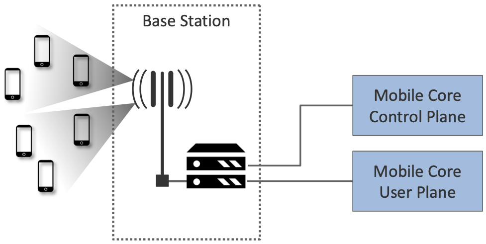
Figure 4. Mobile Core divided into a Control Plane and a User Plane, an architectural feature known as CUPS: Control and User Plane Separation.
The second concept, also depicted in Figure 4, is to partition the Mobile Core into a Control Plane and User Plane. This is similar to the control/data plane split that anyone familiar with the Internet would recognize, and draws in particular on the ideas of software-defined networking (SDN) by placing control and user planes in separate devices. 3GPP has introduced a corresponding acronym—CUPS, Control and User Plane Separation—to denote this idea. One motivation for CUPS is to enable control plane resources and data plane resources to be scaled independently of each other.
Finally, one of the key aspirational goals of 5G is the ability to segregate traffic for different usage domains into isolated network slices, each of which delivers a different level of service to a collection of devices and applications. Thinking of a network slice as a wireless version of a virtual network is a fair approximation, although as we’ll see in later chapters, the implementation details differ.
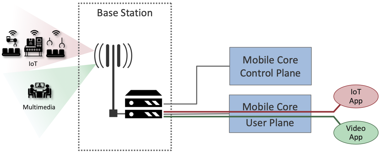
Figure 5. Different usage domains (e.g., IoT and Video Streaming) instantiate distinct network slices to connect a set of devices with one or more applications.
For example, Figure 5 shows two slices, one supporting IoT workloads and the other supporting multimedia streaming traffic. As we’ll see throughout the book, an important question is how slicing is realized end-to-end, across the radio, the RAN, and the Mobile Core. This is done through a combination of allocating distinct resources to each slice and scheduling shared resources on behalf of a set of slices.
2.2 Radio Transmission
Before describing the RAN and Mobile Core subsystems, we first call attention to the obvious: that the base stations that comprise the RAN communicate with UEs via electromagnetic radio waves. This book is not about the physics of this over-the-air communication, and only skims the surface of the information theory that underlies it. But identifying the abstract properties of wireless communication is an essential foundation for understanding the rest of the 5G architecture.
If you imagine the base stations as implementing a multi-layer protocol stack (which, as we’ll see in Chapter 4, they do), then radio transmission is the responsibility of the bottom-most layers of that stack, where (a) digital/analog conversion happens, and (b) analog radio waves are transmitted/received. Chapter 3 introduces radio transmission with enough specificity to lay the necessary foundation, so we’re able to understand all the layers that come above it.
For the purposes of this chapter, we only need to understand the following. First, the RAN is responsible for managing how the radio spectrum is shared among thousands of UEs connected to hundreds of base stations in a geographic region. The primary purpose of Chapter 3 is to establish an abstract interface by which the RAN can manage that spectrum without having to worry about the details of waveforms, modulation, or coding algorithms. All important topics, to be sure, but in the realm of information theory rather than system design that is the focus of this book.
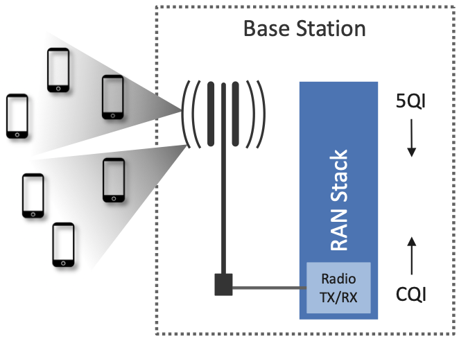
Figure 6. Abstractly, measures of signal quality (CQI) and declarations of intended data delivery quality (5QI) are passed up and down the RAN stack.
Second, there are two important pieces of information shared between the higher layers of the base station protocol stack that manages the RAN as a whole, and the lower layers of the stack that manage radio transmissions on a particular base station. One is the signal-to-noise ratio that the base station observes when communicating with each UE. This is called the Channel Quality Indicator (CQI) and it is passed up from the radio. The other is the quality of service the network wants to give a particular UE. This is called the 5G QoS Identifier (5QI) and it is passed down to the radio. This abstract summary, as shown in Figure 6, is sufficient to introduce the RAN and Mobile Core. We will fill in more details about both of these parameters in Chapter 3.
Uniqueness of Wireless Links
While it is common in networking to abstract the link layer by treating the link as something that just delivers packets at some rate from point A to point B, there are important differences between wireless links and wired links that cannot be entirely abstracted away at higher layers. This is especially true when mobile devices are involved, as the quality of a link will vary depending on the distance between transmitter and receiver, the relative velocity of the endpoints, reflections of radio waves from other objects, and interference from other transmitters. All of these factors come into play in determining the Channel Quality Indicator (CQI).
Further complicating the picture in a mobile network is that a given UE is often within reach of more than one base station, presenting the option to handover the UE from one base station to another. The decision to do so is not just a matter of picking the base station with the best channel quality, but rather a matter of trying to optimize the whole system, in which the goal is to support as many UEs as possible at the desired quality level given the available spectrum and coverage.
Finally, like the rest of the mobile cellular network, the radio comes with a set of acronyms, with LTE (Long-Term Evolution) and NR (New Radio) being the two most widely known. These are marketing terms commonly associated with the radio technology for 4G and 5G, respectively. They are important only in the sense that many of the new features promised by 5G can be directly attributed to improvements in the underlying radio technology. For our purposes, the key is the set of new use cases the upgraded radio technology enables, and why. We introduce these improvements to the radio in Chapter 3, and tie them to the use cases they enable. Subsequent chapters will then explain how the RAN and Mobile Core need to evolve so as to deliver on this potential.
2.3 Radio Access Network
We now describe the RAN by sketching the role each base station plays. Keep in mind this is like describing the Internet by explaining how a router works—not an unreasonable place to start, but it doesn’t fully do justice to the end-to-end story.
First, each base station establishes the wireless channel for a subscriber’s UE upon power-up or upon handover when the UE is active. This channel is released when the UE remains idle for a predetermined period of time. Using 3GPP terminology, this wireless channel is said to provide a radio bearer. The term “bearer” has historically been used in telecommunications (including early wireline technologies such as ISDN) to denote a data channel, as opposed to a channel that carries signaling information.
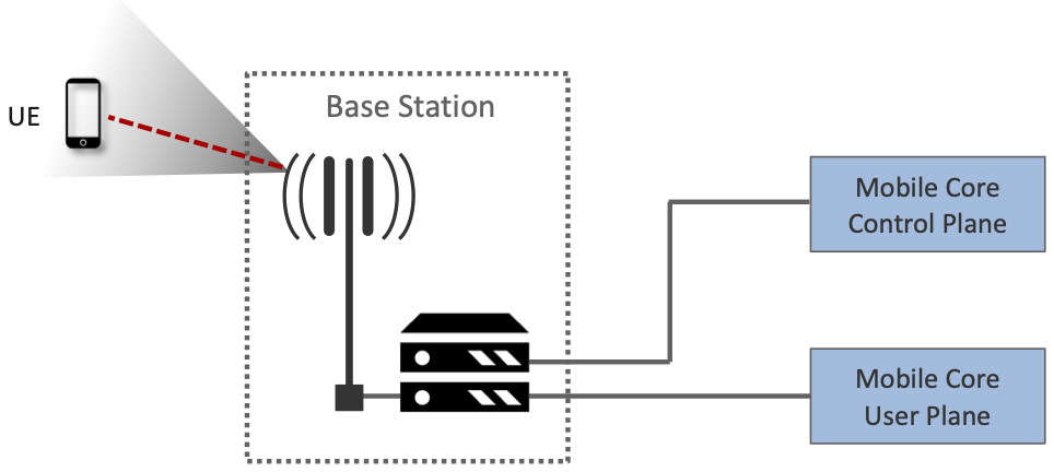
Figure 7. UE detects (and connects to) base station.
Second, each base station establishes “3GPP Control Plane” connectivity between the UE and the corresponding Mobile Core Control Plane component, and forwards signaling traffic between the two. This signaling traffic enables UE authentication, registration, and mobility tracking.
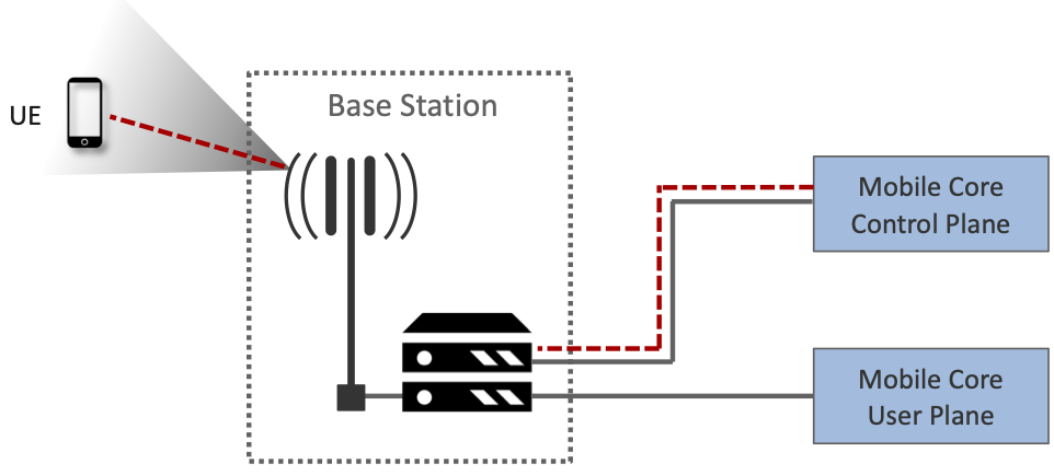
Figure 8. Base Station establishes control plane connectivity between each UE and the Mobile Core.
Third, for each active UE, the base station establishes one or more tunnels to the corresponding Mobile Core User Plane component. Figure 9 shows just two (one for voice and one for data), and while in practice 4G was limited to just two, 5G aspires to support many such tunnels as part of a generalized network slicing mechanism.
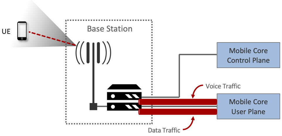
Figure 9. Base station establishes one or more tunnels between each UE and the Mobile Core’s User Plane (known in 3GPP terms as PDU session).
Fourth, the base station forwards both control and user plane packets between the Mobile Core and the UE. These packets are tunneled over SCTP/IP and GTP/UDP/IP, respectively. SCTP (Stream Control Transport Protocol) is an alternative reliable transport to TCP, tailored to carry signaling (control) information for telephony services. GTP (a nested acronym corresponding to (General Packet Radio Service) Tunneling Protocol) is a 3GPP-specific tunneling protocol designed to run over UDP.
It is noteworthy that connectivity between the RAN and the Mobile Core is IP-based. This was introduced as one of the main changes between 3G and 4G. Prior to 4G, the internals of the cellular network were circuit-based, which is not surprising given its origins as a voice network. This also helps to explain why in Section 2.1 we characterized the RAN Backhaul as an overlay running on top of some Layer 2 technology.
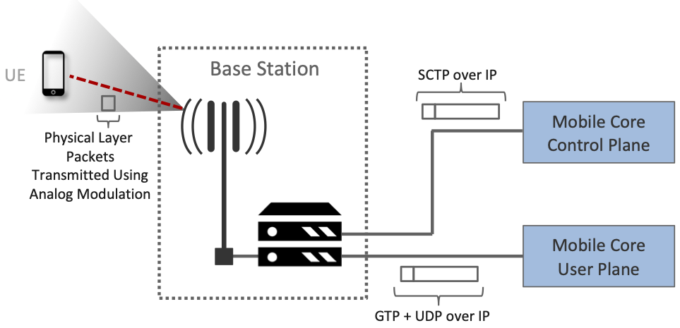
Figure 10. Base Station to Mobile Core (and Base Station to Base Station) control plane tunneled over SCTP/IP and user plane tunneled over GTP/UDP/IP.
Fifth, each base station coordinates UE handovers with neighboring base stations, using direct station-to-station links. Exactly like the station-to-core connectivity shown in the previous figure, these links are used to transfer both control plane (SCTP over IP) and user plane (GTP over UDP/IP) packets. The decision as to when to do a handover is based on the CQI values being reported by the radio on each of the base stations within range of the UE, coupled with the 5QI value those base stations know the RAN has promised to deliver to the UE.
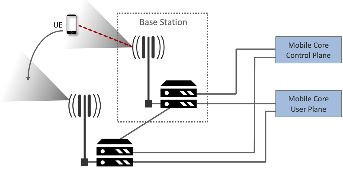
Figure 11. Base Stations cooperate to implement UE hand over.
Sixth, the base stations coordinate wireless multi-point transmission to a UE from multiple base stations, which may or may not be part of a UE handover from one base station to another.
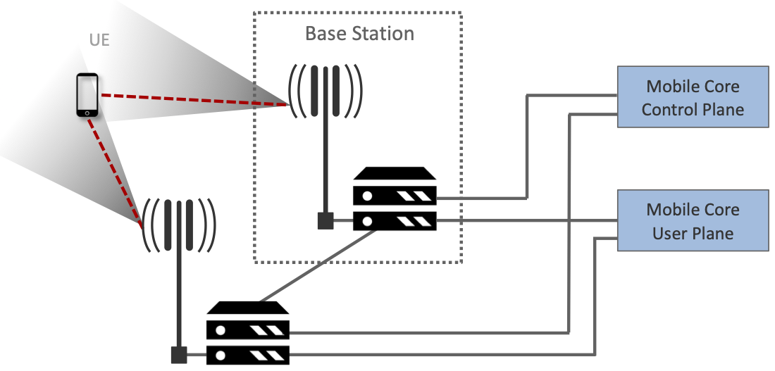
Figure 12. Base Stations cooperate to implement multipath transmission (link aggregation) to UEs.
The main takeaway is that the base station can be viewed as a specialized forwarder. In the Internet-to-UE direction, it fragments outgoing IP packets into physical layer segments and schedules them for transmission over the available radio spectrum, and in the UE-to-Internet direction it assembles physical layer segments into IP packets and forwards them (over a GTP/UDP/IP tunnel) to the upstream user plane of the Mobile Core. Also, based on observations of the wireless channel quality and per-subscriber policies, it decides whether to (a) forward outgoing packets directly to the UE, (b) indirectly forward packets to the UE via a neighboring base station, or (c) utilize multiple paths to reach the UE. The third case has the option of either spreading the physical payloads across multiple base stations or across multiple carrier frequencies of a single base station (including Wi-Fi).
In other words, the RAN as a whole (i.e., not just a single base station) not only supports handovers (an obvious requirement for mobility), but also link aggregation and load balancing, mechanisms that are similar to those found in other types of networks. These functions imply a global decision-making process, whereby it’s possible to forward traffic to a different base station (or to multiple base stations) in an effort to make efficient use of the radio spectrum over a larger geographic area. We will revisit how such RAN-wide (global) decisions can be made using SDN techniques in Chapter 4.
2.4 Mobile Core
At the most basic level, the function of the Mobile Core is to provide packet data network connectivity to mobile subscribers, i.e., connect them to the Internet. (The mobile network assumes that multiple packet data networks can exist, but in practice the Internet is the one that matters). As we noted above, there is more to providing this connectivity than meets the eye: the Mobile Core ensures that subscribers are authenticated and aims to deliver the service qualities to which they have subscribed. As subscribers may move around among base station coverage areas, the Mobile Core needs to keep track of their whereabouts at the granularity of the serving base station. The reasons for this tracking are discussed further in Chapter 5. It is this support for security, mobility, and QoS that differentiates the cellular network from Wi-Fi.
We start with the security architecture, which is grounded in two trust assumptions. First, each base station trusts that it is connected to the Mobile Core by a secure private network, over which it establishes the tunnels introduced in Figure 10: a GTP/UDP/IP tunnel to the Core’s User Plane (Core-UP) and a SCTP/IP tunnel to the Core’s Control Plane (Core-CP). Second, each UE has an operator-provided SIM card, which contains information that uniquely identifies the subscriber and includes a secret key that the UE uses to authenticate itself.
The identifier burned into each SIM card, called an IMSI (International Mobile Subscriber Identity), is a globally unique identifier for every device connected to the global mobile network. Each IMSI is a 64-bit, self-describing identifier, which is to say, it includes a Format field that effectively serves as a mask for extracting other relevant fields. For example, the following is the interpretation we assume in this book (where IMSIs are commonly represented as an up to 15-digit decimal number):
-
MCC: Mobile Country Code (3-digit decimal number).
-
MNC: Mobile Network Code (2 or 3-digit decimal number).
-
ENT: Enterprise Code (3-digit decimal number).
-
SUB: Subscriber (6-digit decimal number).
The first two fields (MCC, MNC) are universally understood to uniquely identify the MNO, while that last two fields are one example of how an MNO might use additional hierarchical structure to uniquely identify every device it serves. We are working towards delivering 5G connectivity to enterprises (hence the ENT field), but other MNOs might assign the last 9 digits using some other structure.
The MCC/MNC pair—which is also called the Public Land Mobile Network (PLMN) identifier—plays a role in roaming: when a UE tries to connect to a “foreign network” those fields are used to find the “home network”, where the rest of the IMSI leads to a subscriber profile that says whether or not roaming is enabled for this device. The following walks through what happens when a device connects to its home network; more information about the global ramifications is given at the end of the section.
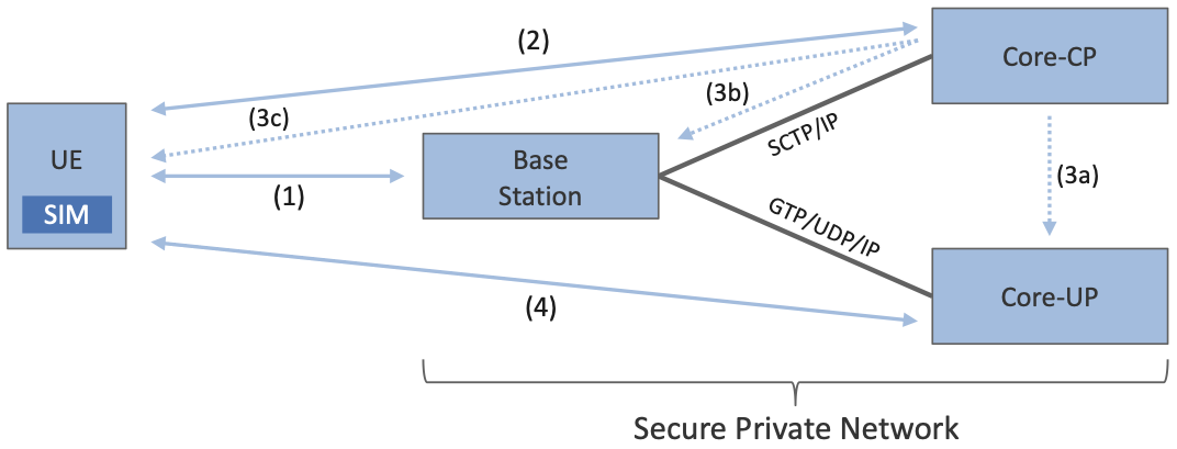
Figure 13. Sequence of steps to establish secure Control and User Plane channels.
Figure 13 shows the per-UE connection sequence. When a UE first becomes active, it communicates with a nearby base station over a temporary (unauthenticated) radio link (Step 1). The base station forwards the request to the Core-CP over the existing SCTP connection, and the Core-CP (assuming it recognizes the IMSI) initiates an authentication protocol with the UE (Step 2). 3GPP identifies a set of options for authentication and encryption, where the actual protocols used are an implementation choice. For example, Advanced Encryption Standard (AES) is one of the options for encryption. Note that this authentication exchange is initially in the clear since the base station to UE link is not yet secure.
Once the UE and Core-CP are satisfied with each other’s identity, the Core-CP informs the other 5GC components of the parameters they will need to service the UE (Step 3). This includes: (a) instructing the Core-UP to initialize the user plane (e.g., assign an IP address to the UE and set the appropriate 5QI); (b) instructing the base station to establish an encrypted channel to the UE; and (c) giving the UE the symmetric key it will need to use the encrypted channel with the base station. The symmetric key is encrypted using the public key of the UE (so only the UE can decrypt it, using its secret key). Once complete, the UE can use the end-to-end user plane channel through the Core-UP (Step 4).
There are three additional details of note about this process. First, the secure control channel between the UE and the Core-CP set up during Step 2 remains available, and is used by the Core-CP to send additional control instructions to the UE during the course of the session. In other words, unlike the Internet, the network is able to “control” the communication settings in edge devices.
Second, the user plane channel established during Step 4 is referred to as the Default Data Radio Bearer, but additional channels can be established between the UE and Core-UP, each with a potentially different 5QI. This might be done on an application-by-application basis, for example, based on policies present in the Core-CP for packets that require special/different treatment.
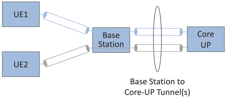
Figure 14. Sequence of per-hop tunnels involved in an end-to-end User Plane channel.
In practice, these per-flow tunnels are often bundled into a single inter-component tunnel, which makes it impossible to differentiate the level of service given to any particular end-to-end UE channel. This is a limitation of 4G that 5G has ambitions to correct as part of its support for network slicing.
Support for mobility can now be understood as the process of re-executing one or more of the steps shown in Figure 13 as the UE moves throughout the RAN. The unauthenticated link indicated by (1) allows the UE to be known to all base stations within range. (We refer to these as potential links in later chapters.) Based on the signal’s measured CQI, the base stations communicate directly with each other to make a handover decision. Once made, the decision is then communicated to the Mobile Core, re-triggering the setup functions indicated by (3), which in turn re-builds the user plane tunnel between the base station and the Core-UP shown in Figure 14. One of the most unique features of the cellular network is that the Mobile Core’s user plane buffers data while idle UEs are transiting to active state, thereby avoiding dropped packets and subsequent end-to-end retransmissions.
In other words, the mobile cellular network maintains the UE session in the face of mobility (corresponding to the control and data channels depicted by (2) and (4) in Figure 13, respectively), but it is able to do so only when the same Mobile Core serves the UE (i.e., only the base station changes). This would typically be the case for a UE moving within a metropolitan area. Moving between metro areas—and hence, between Mobile Cores—is indistinguishable from power cycling a UE. The UE is assigned a new IP address and no attempt is made to buffer and subsequently deliver in-flight data. Independent of mobility, but relevant to this discussion, any UE that becomes inactive for a period of time also loses its session, with a new session established and a new IP address assigned when the UE becomes active again.
Note that this session-based approach can be traced to the mobile cellular network’s roots as a connection-oriented network. An interesting thought experiment is whether the Mobile Core will continue to evolve so as to better match the connectionless assumptions of the Internet protocols that typically run on top of it.
We conclude this overview of the Mobile Core by returning to the role it plays in implementing a global mobile network. It is probably already clear that each MNO implements a database of subscriber information, allowing it to map an IMSI to a profile that records what services (roaming, data plane, hot spot support) the subscriber is paying for. This record also includes the international phone number for the device. How this database is realized is an implementation choice (of which we’ll see an example in Chapter 5), but 3GPP defines an interface by which one Mobile Core (running on behalf of one MNO) queries another Mobile Core (running on behalf of some other MNO), to map between the IMSI, the phone number, and the subscriber profile.
2.5 Managed Cloud Service
The architectural overview presented up to this point focuses on the functional elements of the mobile cellular network. We now turn our attention to how this functionality is operationalized, and we do so in a decidedly software-defined and cloud-native way. This lays the foundation for the rest of the book, which builds towards supporting 5G connectivity as a managed cloud service. This is a marked change from the conventional Telco approach, whereby an operator bought purpose-built devices from a handful of vendors, and then managed them using the legacy OSS/BSS machinery that was originally designed for the telephony network.1
OSS/BSS stands for Operation Support System / Business Support System, and even traditional MNOs are now re-imagining them by adopting cloud practices. But this transition is a slow process due to all the legacy systems the Telcos need to continue supporting.
When we talk about “operationalizing” a network, we are referring to a substantial system that operators (whether they are traditional MNOs or cloud service providers) use to activate and manage all the constituent components (whether they are purpose-built devices or software running on commodity hardware). And because these network operators are people, one high-level summary is that this management layer (whether it is an OSS/BSS or a cloud orchestrator) provides a way to map high-level Intents onto low-level Actions.
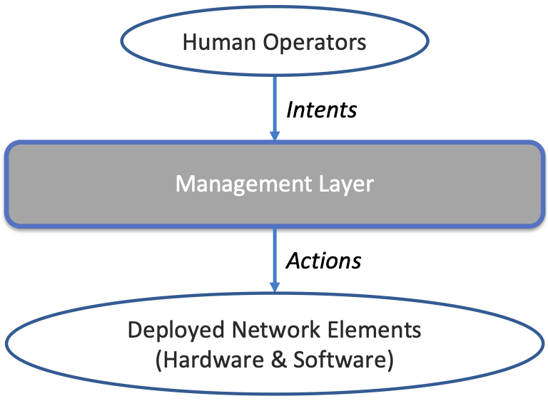
Figure 15. High-level summary of the role operationalization plays in a network deployment.
This overview, as illustrated in Figure 15, is obviously quite abstract. To make the discussion more concrete, we use an open source implementation, called Aether, as an example. Aether is a Kubernetes-based edge cloud, augmented with a 5G-based connectivity service. Aether is targeted at enterprises that want to take advantage of 5G connectivity in support of edge applications that require predictable, low-latency connectivity. In short, “Kubernetes-based” means Aether is able to host container-based services, with Kubernetes being the platform used to orchestrate the services, and “5G-based connectivity” means Aether is able to connect those services to mobile devices throughout the enterprise’s physical environment.
Aether supports this combination by implementing both the RAN and the user plane of the Mobile Core on-prem, as cloud-native workloads co-located on the Aether cluster. This is often referred to as local breakout because it enables direct communication between mobile devices and edge applications without data traffic leaving the enterprise, in contrast to what would happen with standard, operator-provided 5G service. This scenario is depicted in Figure 16, which shows unnamed edge applications running on-prem. Those edge applications might include the local processing of sensor data or control applications for the IoT devices, for example.
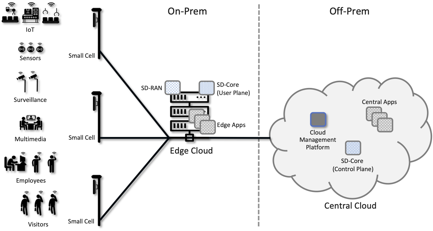
Figure 16. Overview of Aether as a hybrid cloud, with edge apps and the 5G data plane (called local breakout) running on-prem and various management and control-related workloads running in a central cloud.
The approach includes both edge (on-prem) and centralized (off-prem) components. This is true for edge apps, which often have a centralized counterpart running in a commodity cloud. It is also true for the 5G Mobile Core, where the on-prem User Plane (UP) is paired with a centralized Control Plane (CP). The central cloud shown in this figure might be private (i.e., operated by the enterprise), public (i.e., operated by a commercial cloud provider), or some combination of the two (i.e., not all centralized elements need to run in the same cloud).
Also shown in Figure 16 is a centralized Control and Management Platform. This is Aether’s version of the “Management Layer” depicted in Figure 15, and it represents all the functionality needed to offer Aether as a managed cloud service, with system administrators using a portal exported by this platform to operate the underlying infrastructure and services within their enterprise.
Once we deconstruct the individual components in more details in the next three chapters, we return to the question of how the resulting set of components can be assembled into an operational edge cloud in Chapter 6. The end result is 5G connectivity as a managed cloud service.


 1251
1251

 被折叠的 条评论
为什么被折叠?
被折叠的 条评论
为什么被折叠?
 到【灌水乐园】发言


