


开始之前需要简单了解spi的原理,这里用st7735的驱动来讲解 2024 5 12
在数据手册的6.2 Interface Logic Pin(接口逻辑引脚) 15,16页
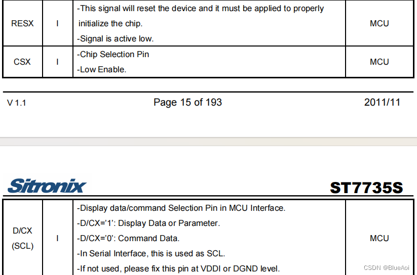
可以看到RES CSX D/CX的字样,可以看到st7735是
res低电平复位
csx低电平使能
1时发送D(data)(数据),0时发送C(command)(指令),然后他说如果不使用这个引脚,就连接到vcc或者gnd上,避免干扰
这时发送数据或者指令的逻辑就出来了
1.先将csx弄上低电平,象征着开始
2.把D/CX弄上高电平,表示发送数据,或者弄成低电平表示发送指令
3.发送数据就要用到SDA引脚(这里是一位一位的传),如果首位是1,就将SDA设置为高电平,是0就设置为低电平
4.接着就是将scl时间线先下拉,在上拉,接受sda的数据,这样就传递了一位数据
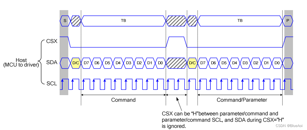
在数据手册的37页,可以看到发送的时序图
第二根先cs为0的时候开始,当scl线上出现上升的箭头的时候,接受sda的数据,貌似spi有4中模式,一种是左边向上箭头开始接受数据,同理有左下,右上,右下,对应后面的mode
如果接收结束,把cs设置为1,这样后面的数据就会被ignore(忽略)
luma.core.interface.serial 库的spi解读
惯例还是扒下来
@lib.spidev
class spi(bitbang):
    """
    Wraps an `SPI <https://en.wikipedia.org/wiki/Serial_Peripheral_Interface_Bus>`_
    (Serial Peripheral Interface) bus to provide :py:func:`data` and
    :py:func:`command` methods.

    :param spi: SPI implementation (must be compatible with `spidev <https://pypi.org/project/spidev>`_)
    :param gpio: GPIO interface (must be compatible with `RPi.GPIO <https://pypi.org/project/RPi.GPIO>`__).
        For slaves that don't need reset or D/C functionality, supply a
        :py:class:`noop` implementation instead.
    :param port: SPI port, usually 0 (default) or 1.
    :type port: int
    :param device: SPI device, usually 0 (default) or 1.
    :type device: int
    :param bus_speed_hz: SPI bus speed, defaults to 8MHz.
    :type bus_speed_hz: int
    :param transfer_size: Maximum amount of bytes to transfer in one go. Some implementations
        only support a maximum of 64 or 128 bytes, whereas RPi/py-spidev supports
        4096 (default).
    :type transfer_size: int
    :param gpio_DC: The GPIO pin to connect data/command select (DC) to (defaults to 24).
    :type gpio_DC: int
    :param gpio_RST: The GPIO pin to connect reset (RES / RST) to (defaults to 25).
    :type gpio_RST: int
    :param spi_mode: SPI mode as two bit pattern of clock polarity and phase [CPOL|CPHA], 0-3 (default:None)
    :type spi_mode: int
    :param reset_hold_time: The number of seconds to hold reset active. Some devices may require
        a duration of 100ms or more to fully reset the display (default: 0)
    :type reset_hold_time: float
    :param reset_release_time: The number of seconds to delay afer reset. Some devices may require
        a duration of 150ms or more after reset was triggered before the device can accept the
        initialization sequence (default: 0)
    :type reset_release_time: float
    :raises luma.core.error.DeviceNotFoundError: SPI device could not be found.
    :raises luma.core.error.UnsupportedPlatform: GPIO access not available.
    """
    def __init__(self, spi=None, gpio=None, port=0, device=0,
                 bus_speed_hz=8000000, transfer_size=4096,
                 gpio_DC=24, gpio_RST=25, spi_mode=None,
                 reset_hold_time=0, reset_release_time=0, **kwargs):
        assert bus_speed_hz in [mhz * 1000000 for mhz in [0.5, 1, 2, 4, 8, 16, 20, 24, 28, 32, 36, 40, 44, 48, 50, 52]]   #判断频率是否在范围内

        bitbang.__init__(self, gpio, transfer_size, reset_hold_time, reset_release_time, DC=gpio_DC, RST=gpio_RST)    #继承bitbang

        try:
            self._spi = spi or self.__spidev__()
            self._spi.open(port, device)
            if spi_mode:
                self._spi.mode = spi_mode
            if "cs_high" in kwargs:
                import warnings
                warnings.warn(
                    "SPI cs_high is no longer supported in kernel 5.4.51 and beyond, so setting parameter cs_high is now ignored!",
                    RuntimeWarning
                )
        except (IOError, OSError) as e:
            if e.errno == errno.ENOENT:
                raise luma.core.error.DeviceNotFoundError('SPI device not found')
            else:  # pragma: no cover
                raise

        self._spi.max_speed_hz = bus_speed_hz

    def _write_bytes(self, data):
        self._spi.writebytes(data)

    def cleanup(self):
        """
        Clean up SPI & GPIO resources.
        """
        self._spi.close()
        super(spi, self).cleanup()
第一,初始化函数
首先就是**@lib.spidev**就相当于引用lib.spidev模块中的功能或方法。
1.定义了spi的方式为none,就会使用lib.spidev的.__spidev__()的方法来创建一个spi实例,可惜的是无法在macos上使用这个库的spi
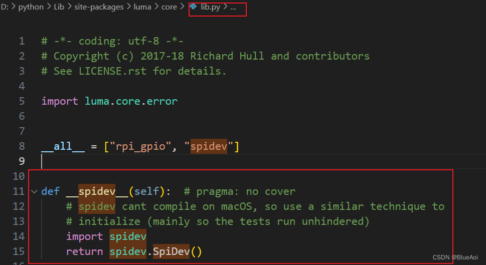
我想看看spidev的源码,可惜不能点进去,源码为c语言写的,是spidev_module.c编译而来的,哈哈哈哈哈哈不知道它是怎么导入的import spidev 过几天去了解一下,还有这个在我的windows电脑上无法通过pip install spidev下载,提示缺少cl.exe和wheel,后面我把源码下载下来,自己编译也不行,后来在阿里云白嫖的linux服务器上编译成功了,是spidev.cpython-38-x86_64-linux-gnu.so这个文件,过几天了解一下这其中的原理哈哈哈
但是还有一个疑点,源代码上写着
- spidev_module.c - Python bindings for Linux SPI access through spidev 是给linux用的spi 但是在
__spidev__中却没有提到windows不能使用,有点奇怪.
2.port和device=0
端口有spi 0 和spi 1 device就是 ls /dev/spi*这个命令看到的那样,就是片段cs线
所以默认都是0,0
- SPI0:
- MOSI (Master Out Slave In, 主机输出从机输入): GPIO 19
- MISO (Master In Slave Out, 主机输入从机输出): GPIO 11
- SCLK (Serial Clock, 串行时钟): GPIO 10
- CS/CE0 (Chip Select, 片选0): GPIO 8 (默认的设备选择引脚)
- CS/CE1 (Chip Select, 片选1): GPIO 7 (第二个设备选择引脚,如果需要)
- SPI1:
3**.scl的频率**
这个频率的意义是什么:很久以前听到的超频一直不知道是什么意思,其实就是改频率,频率快,这个上下震荡就快,接受的数据就越多
4.单次最大传输大小(4096)
5.坑点…
默认DC为24,RST为25 是bcm编码,不是物理引脚,纠结了一天,mode默认就是sck左上开始读数据
意义是什么:很久以前听到的超频一直不知道是什么意思,其实就是改频率,频率快,这个上下震荡就快,接受的数据就越多
4.单次最大传输大小(4096)
5.坑点…
默认DC为24,RST为25 是bcm编码,不是物理引脚,纠结了一天,mode默认就是sck左上开始读数据
-------没完—


 被折叠的 条评论
为什么被折叠?
被折叠的 条评论
为什么被折叠?
 到【灌水乐园】发言


