


c#操作solid_edge
以下所有代码都已提交giteehttps://gitee.com/qimowei/solid_edge.git
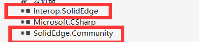
在所有操作之前,必须要进行引入Solid Edge的dll文件

- 以下所有功能展示
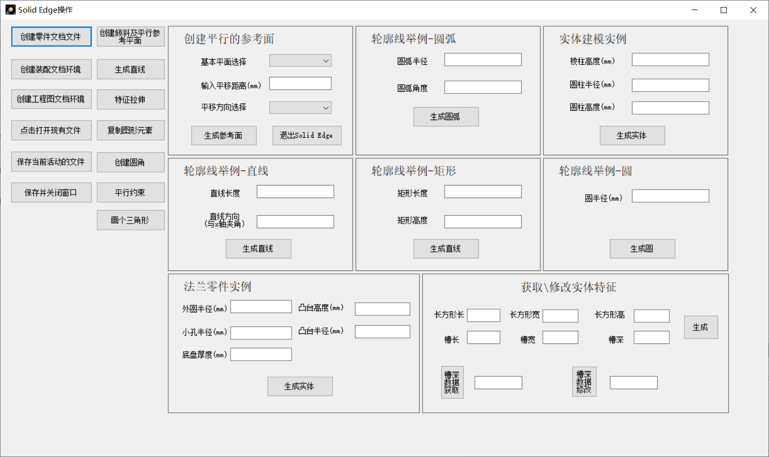
一、基本操作
1、简单打开solid edge软件
1、引入包
using SolidEdgeCommunity.Extensions;
using SolidEdgeConstants;
using SolidEdgeFrameworkSupport;
using SolidEdgeGeometry;
using SolidEdgePart;
using FeaturePropertyConstants = SolidEdgePart.FeaturePropertyConstants;
using FeatureStatusConstants = SolidEdgePart.FeatureStatusConstants;
using FeatureTopologyQueryTypeConstants = SolidEdgeGeometry.FeatureTopologyQueryTypeConstants;
using PatternOffsetTypeConstants = SolidEdgeFrameworkSupport.PatternOffsetTypeConstants;
using ProfileValidationType = SolidEdgePart.ProfileValidationType;
using ReferenceElementConstants = SolidEdgePart.ReferenceElementConstants;
using SEPatternRecognitionLevel = SolidEdgeConstants.SEPatternRecognitionLevel;
2、创建按钮,启动Solid Edge
private void button1_Click_1(object sender, EventArgs e)
{
    //建立objApp变量,Application是SolidEdgeFrameWork框架结构类型库的子类
    private SolidEdgeFramework.Application objApp;

    //建立objDoc变量,PartDocument是SolidEdgePart的子类,是一个数据文档,包含零件的几何和属性数据。
    private SolidEdgePart.PartDocument objDoc;
    //@1 连接solidedge应用
    // Register with OLE to handle concurrency issues on the current thread.
    SolidEdgeCommunity.OleMessageFilter.Register();

    //Connect to or start Solid Edge.这个方法里面的两个参数是开启功能:1、如果未启动就启动一个,2、如果启动了就显示,
    objApp = SolidEdgeCommunity.SolidEdgeUtils.Connect(true, true);

    //Creates a new part document.
    objDoc = objApp.Documents.AddPartDocument();

    objApp.DoIdle();
    objApp.Visible = true;
}- 注释
//创建零件文档
objApp.Documents.AddPartDocument();
//创建装配文档
objApp.Documents.AddAssemblyDocument();
//创建工程图文档
objApp.Documents.AddDraftDocument();
2、选择文件并打开
private void button4_Click(object sender, EventArgs e)
{
    OpenFileDialog fileDialog = new OpenFileDialog();
    fileDialog.Multiselect = true;
    fileDialog.Title = "请选择文件";
    fileDialog.Filter = "所有文件(*.par)|*.par";
    if (fileDialog.ShowDialog() == DialogResult.OK)
    {
        string filePath = fileDialog.FileName;
        //@1 连接solidedge应用
        // Register with OLE to handle concurrency issues on the current thread.
        SolidEdgeCommunity.OleMessageFilter.Register();

        //Connect to or start Solid Edge.这个方法里面的两个参数是开启功能:1、如果未启动就启动一个,2、如果启动了就显示,
        objApp = SolidEdgeCommunity.SolidEdgeUtils.Connect(true, true);

        //open a new part document.
        objDoc = objApp.Documents.Open(filePath);

        objApp.DoIdle();
        objApp.Visible = true;
    }
    else
    {
        MessageBox.Show("路径获取失败", "错误提示", MessageBoxButtons.OK, MessageBoxIcon.Information);
    }
}- 核心代码
objApp.Documents.Open(filePath);- filePath是从文件选择框获取的,不在这里赘述,可以参照另一文章或者百度
3、保存当前活动的文件
/**
         * 保存当前活动的文件
         */
private void button5_Click(object sender, EventArgs e)
{
    FolderBrowserDialog dialog = new FolderBrowserDialog();
    dialog.Description = "请选择文件路径";
    DateTime dateTime = DateTime.Now;
    if (dialog.ShowDialog() == DialogResult.OK)
    {
        string foldPath = dialog.SelectedPath;

        string newFilePath = foldPath + @"\" + dateTime.ToString("yyyyMMddHHmmss") + ".par";
        //@1 连接solidedge应用
        // Register with OLE to handle concurrency issues on the current thread.
        SolidEdgeCommunity.OleMessageFilter.Register();

        //Connect to or start Solid Edge.这个方法里面的两个参数是开启功能:1、如果未启动就启动一个,2、如果启动了就显示,
        objApp = SolidEdgeCommunity.SolidEdgeUtils.Connect(true, true);

        //获取当前活动的数据文档,并报错在当前位置的当前文件名,如果是新创建没有文件名的方法不能用这个,得用SaveAs
        //objApp.GetActiveDocument().Save();
        try
        {
            objApp.GetActiveDocument().SaveAs(newFilePath);
            objApp.DoIdle();
            objApp.Visible = true;
            MessageBox.Show("保存成功");
        }
        catch
        {
            MessageBox.Show("没有正在活动的文档");
        }
    }
    else
    {
        MessageBox.Show("路径获取失败", "错误提示", MessageBoxButtons.OK, MessageBoxIcon.Information);
    }
}- 核心代码
//获取当前活动的数据文档,并报错在当前位置的当前文件名,如果是新创建没有文件名的方法不能用这个,得用SaveAs
objApp.GetActiveDocument().Save();
//没有初始文件名,相当于另存为
objApp.GetActiveDocument().SaveAs(newFilePath);- 这里有个坑,书本中是用VB编写的,书写方式是
objApp.ActiveDocument.SaveAs(newFilePath);但是c#中的dll没有这个接口,是通过get方法获取到的。
4、退出软件
/**
   * 退出软件
  */
private void button6_Click(object sender, EventArgs e)
{
    //@1 连接solidedge应用
    // Register with OLE to handle concurrency issues on the current thread.
    SolidEdgeCommunity.OleMessageFilter.Register();

    //Connect to or start Solid Edge.这个方法里面的两个参数是开启功能:1、如果未启动就启动一个,2、如果启动了就显示,
    objApp = SolidEdgeCommunity.SolidEdgeUtils.Connect(true, true);

    objApp.GetActiveDocument().Save();

    objApp.Quit();
}- 核心代码
objApp.Quit();5、旋转、偏移平面
/**
         * 旋转、偏移平面
         */
private void button7_Click(object sender, EventArgs e)
{
    //@1 连接solidedge应用
    // Register with OLE to handle concurrency issues on the current thread.
    SolidEdgeCommunity.OleMessageFilter.Register();

    //Connect to or start Solid Edge.这个方法里面的两个参数是开启功能:1、如果未启动就启动一个,2、如果启动了就显示,
    objApp = SolidEdgeCommunity.SolidEdgeUtils.Connect(true, true);

    //创建装配文档
    AssemblyDocument objAssyDoc = objApp.Documents.AddAssemblyDocument();

    //获得装配参考面集合对象
    AsmRefPlanes asmRefPlanes = objAssyDoc.AsmRefPlanes;

    //建立与yoz面成120°的参考面
    //先选择yoz参考面,作为母平面
    AsmRefPlane objPPlane = asmRefPlanes.Item(2);
    //然后旋转120°
    AsmRefPlane asmRefPlane = asmRefPlanes.AddAngularByAngle(
        //设置倾斜的母平面
        ParentPlane: objPPlane,
        //旋转角度
        Angle: (2 * PI / 3),
        //与母平面objPPlane相交来定义倾斜平面的旋转轴
        Pivot: asmRefPlanes.Item(1),
        //定义新参考平面轴的原点
        PivotOrigin: ReferenceElementConstants.igPivotEnd,
        //标识顺时针旋转
        NormalSide: ReferenceElementConstants.igNormalSide,
        //这个打开标识为局部的
        Local: true
    );

    //创建零件文档
    PartDocument objPartDoc = objApp.Documents.AddPartDocument();

    //获得零件参考面集合对象
    RefPlanes refPlanes = objPartDoc.RefPlanes;

    //建立与xoy基准面平行的参考平面
    RefPlane refPlane = refPlanes.AddParallelByDistance(
        //定义母平面为xoy面
        ParentPlane: refPlanes.Item(1),
        //定义和母平面的距离
        Distance: 0.1,
        //定义新增参考面为正向的
        NormalSide: ReferenceElementConstants.igNormalSide,
        //标识不是局部的
        Local: false
    );

    objApp.DoIdle();
    objApp.Visible = true;
}- 核心代码
//获得装配参考面集合对象
AsmRefPlanes asmRefPlanes = objAssyDoc.AsmRefPlanes;
//建立与yoz面成120°的参考面
//先选择yoz参考面,作为母平面
AsmRefPlane objPPlane = asmRefPlanes.Item(2);
//然后旋转120°
AsmRefPlane asmRefPlane = asmRefPlanes.AddAngularByAngle(
//设置倾斜的母平面
ParentPlane: objPPlane,
//旋转角度
Angle: (2 * PI / 3),
//与母平面objPPlane相交来定义倾斜平面的旋转轴
Pivot: asmRefPlanes.Item(1),
//定义新参考平面轴的原点
PivotOrigin: ReferenceElementConstants.igPivotEnd,
//标识顺时针旋转
NormalSide: ReferenceElementConstants.igNormalSide,
//这个打开标识为局部的
Local: true
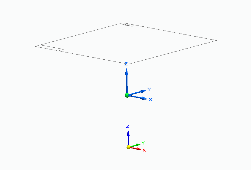
);操作结果:
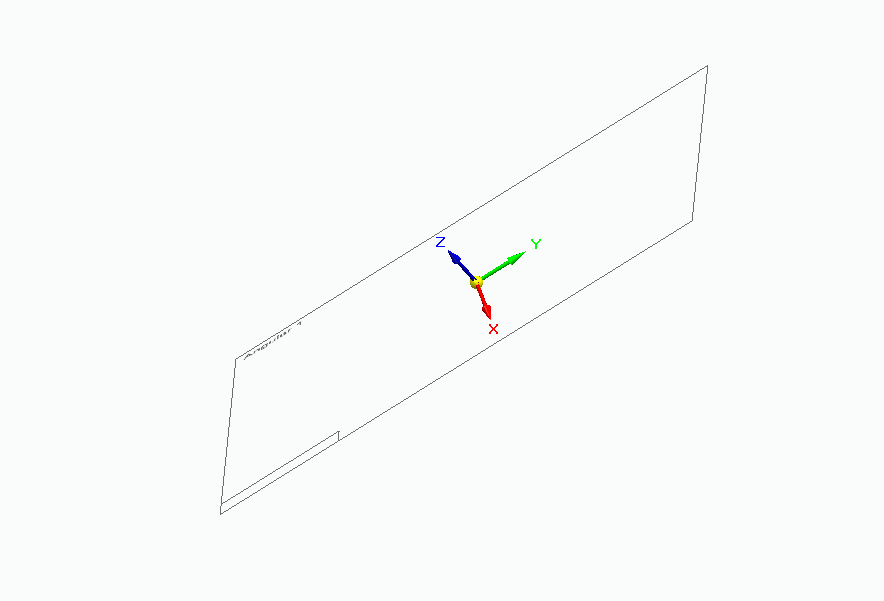
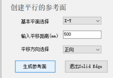
6、参数化,旋转、偏移平面
/**
         * 参数化,旋转、偏移平面
         */
private void button8_Click(object sender, EventArgs e)
{
    //@1 连接solidedge应用
    // Register with OLE to handle concurrency issues on the current thread.
    SolidEdgeCommunity.OleMessageFilter.Register();

    //Connect to or start Solid Edge.这个方法里面的两个参数是开启功能:1、如果未启动就启动一个,2、如果启动了就显示,
    objApp = SolidEdgeCommunity.SolidEdgeUtils.Connect(true, true);

    //创建零件文档
    PartDocument objPartDoc = objApp.Documents.AddPartDocument();

    //获得零件参考面集合对象
    RefPlanes refPlanes = objPartDoc.RefPlanes;

    //获取动态参数
    string combox1 = comboBox1.Text;
    double textbox1 = double.Parse(textBox1.Text);
    string combox2 = comboBox2.Text;

    //n代表平面代号码,默认为1
    int n = 1;
    //判断平面编号
    if (combox1 == "X-Z")
    {
        n = 3;
    }
    else if (combox1 == "Y-Z")
    {
        n = 2;
    }
    //m代表平移距离
    double m = textbox1 / 1000;
    //g代表方向
    ReferenceElementConstants g = combox2 == "正向" ? ReferenceElementConstants.igNormalSide : ReferenceElementConstants.igReverseNormalSide;

    //建立与xoy基准面平行的参考平面
    RefPlane refPlane = refPlanes.AddParallelByDistance(
        //定义母平面为xoy面
        ParentPlane: refPlanes.Item(n),
        //定义和母平面的距离
        Distance: m,
        //定义新增参考面为正向的
        NormalSide: g,
        //标识不是局部的
        Local: false
    );
    //RefAxes refAxes = objPartDoc.RefAxes;
    //Profile profile;
    //RefAxis refAxis = profile.SetAxisOfRevolution(LineForAxis:objLine);
    objApp.DoIdle();
    objApp.Visible = true;
}- 核心代码
//获取动态参数
    string combox1 = comboBox1.Text;
    double textbox1 = double.Parse(textBox1.Text);
    string combox2 = comboBox2.Text;

    //n代表平面代号码,默认为1
    int n = 1;
    //判断平面编号
    if (combox1 == "X-Z")
    {
        n = 3;
    }
    else if (combox1 == "Y-Z")
    {
        n = 2;
    }
    //m代表平移距离
    double m = textbox1 / 1000;
    //g代表方向
ReferenceElementConstants g = combox2 == "正向" ? ReferenceElementConstants.igNormalSide : ReferenceElementConstants.igReverseNormalSide;-
知识点,c#中下拉选择框指定默认值
-
在Designer.cs文件中,有load的代码
-
找到下拉选择框组件代码,然后加上如下代码
this.comboBox1.SelectedIndex = 0;- 操作结果:
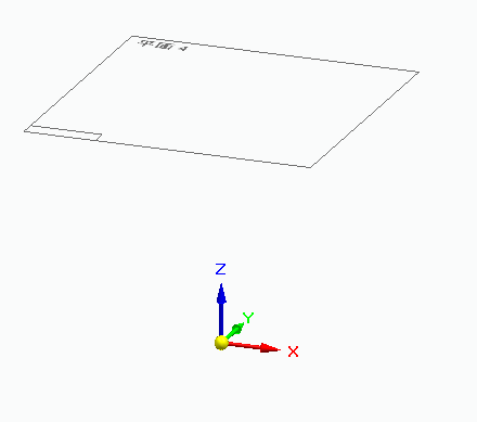
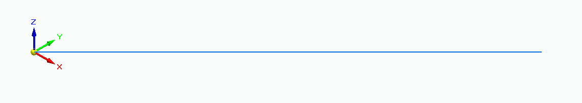
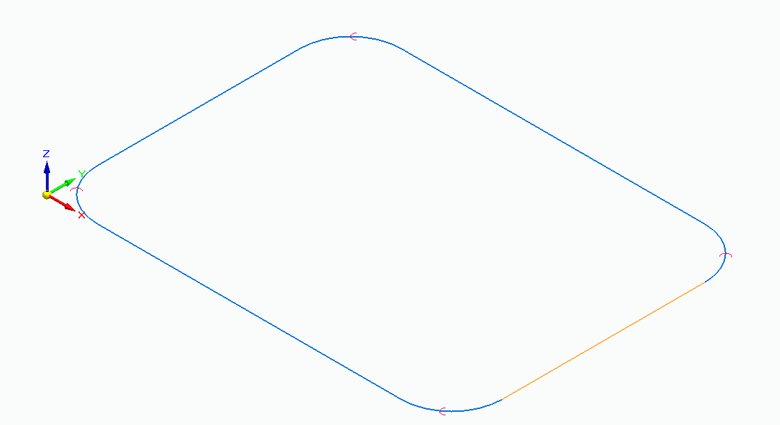
7、划直线
/**
         * 划直线
         */
private void button10_Click(object sender, EventArgs e)
{
    //@1 连接solidedge应用
    // Register with OLE to handle concurrency issues on the current thread.
    SolidEdgeCommunity.OleMessageFilter.Register();

    //Connect to or start Solid Edge.这个方法里面的两个参数是开启功能:1、如果未启动就启动一个,2、如果启动了就显示,
    objApp = SolidEdgeCommunity.SolidEdgeUtils.Connect(true, true);

    //创建零件文档
    PartDocument objPartDoc = objApp.Documents.AddPartDocument();

    Lines2d lines2d = objPartDoc.ProfileSets.Add().Profiles.Add(pRefPlaneDisp: objPartDoc.RefPlanes.Item(1)).Lines2d;

    lines2d.AddBy2Points(0, 0, 0.01, 0.01);

    objApp.DoIdle();
    objApp.Visible = true;
}- 核心代码
//创建零件文档
PartDocument objPartDoc = objApp.Documents.AddPartDocument();

Lines2d lines2d = objPartDoc.ProfileSets.Add().Profiles.Add(pRefPlaneDisp: objPartDoc.RefPlanes.Item(1)).Lines2d;

lines2d.AddBy2Points(0, 0, 0.01, 0.01);
结果展示:
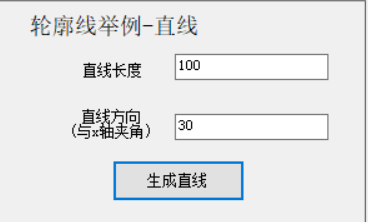
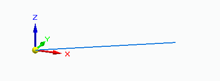
8、带参-划直线
/**
         * 带参-划直线
         */
private void button12_Click(object sender, EventArgs e)
{
    if (textBox2.Text == "" || textBox3.Text == "")
    {
        MessageBox.Show("必填项不能为空");
        return;
    }
    //@1 连接solidedge应用
    // Register with OLE to handle concurrency issues on the current thread.
    SolidEdgeCommunity.OleMessageFilter.Register();

    //Connect to or start Solid Edge.这个方法里面的两个参数是开启功能:1、如果未启动就启动一个,2、如果启动了就显示,
    objApp = SolidEdgeCommunity.SolidEdgeUtils.Connect(true, true);

    //创建零件文档
    PartDocument objPartDoc = objApp.Documents.AddPartDocument();

    Profile objProfile = objPartDoc.ProfileSets.Add().Profiles.Add(objPartDoc.RefPlanes.Item(1));

    //获得直线参数
    double line_angle = double.Parse(textBox3.Text) * PI / 180;
    double line_llen = double.Parse(textBox2.Text) / 1000;

    objProfile.Lines2d.AddByPointAngleLength(0, 0, line_angle, line_llen);

    objApp.DoIdle();
    objApp.Visible = true;
}- 核心代码
//获得直线参数
double line_angle = double.Parse(textBox3.Text) * PI / 180;
double line_llen = double.Parse(textBox2.Text) / 1000;

objProfile.Lines2d.AddByPointAngleLength(0, 0, line_angle, line_llen);- 结果展示:
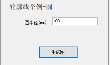
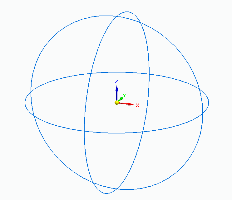
9、画圆
/**
         * 画圆
         */
private void button11_Click(object sender, EventArgs e)
{
    if (textBox5.Text == "")
    {
        MessageBox.Show("必填项不能为空");
        return;
    }
    //@1 连接solidedge应用
    // Register with OLE to handle concurrency issues on the current thread.
    SolidEdgeCommunity.OleMessageFilter.Register();

    //Connect to or start Solid Edge.这个方法里面的两个参数是开启功能:1、如果未启动就启动一个,2、如果启动了就显示,
    objApp = SolidEdgeCommunity.SolidEdgeUtils.Connect(true, true);

    //创建零件文档
    PartDocument objPartDoc = objApp.Documents.AddPartDocument();

    Profile objProfile1 = objPartDoc.ProfileSets.Add().Profiles.Add(objPartDoc.RefPlanes.Item(1));
    Profile objProfile2 = objPartDoc.ProfileSets.Add().Profiles.Add(objPartDoc.RefPlanes.Item(2));
    Profile objProfile3 = objPartDoc.ProfileSets.Add().Profiles.Add(objPartDoc.RefPlanes.Item(3));

    //获得直线参数
    double radius = double.Parse(textBox5.Text) / 1000;
    //原点加半径
    objProfile1.Circles2d.AddByCenterRadius(0, 0, radius);
    objProfile2.Circles2d.AddByCenterRadius(0, 0, radius);
    objProfile3.Circles2d.AddByCenterRadius(0, 0, radius);

    objApp.DoIdle();
    objApp.Visible = true;
}- 核心代码
Profile objProfile1 = objPartDoc.ProfileSets.Add().Profiles.Add(objPartDoc.RefPlanes.Item(1));
 //获得直线参数
double radius = double.Parse(textBox5.Text) / 1000;
 //原点加半径
objProfile1.Circles2d.AddByCenterRadius(0, 0, radius);- 结果展示:
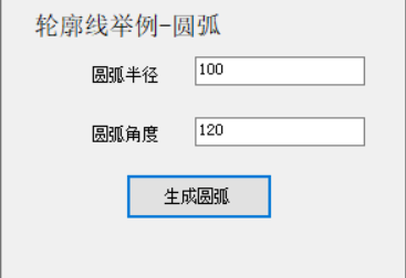
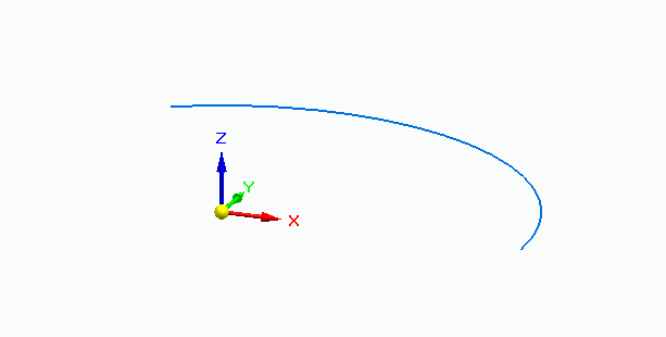
10、画弧线
/**
         * 画弧线
         */
private void button13_Click(object sender, EventArgs e)
{
    if (textBox4.Text == "" || textBox6.Text == "")
    {
        MessageBox.Show("必填项不能为空");
        return;
    }
    //@1 连接solidedge应用
    // Register with OLE to handle concurrency issues on the current thread.
    SolidEdgeCommunity.OleMessageFilter.Register();

    //Connect to or start Solid Edge.这个方法里面的两个参数是开启功能:1、如果未启动就启动一个,2、如果启动了就显示,
    objApp = SolidEdgeCommunity.SolidEdgeUtils.Connect(true, true);

    //创建零件文档
    PartDocument objPartDoc = objApp.Documents.AddPartDocument();

    Profile objProfile = objPartDoc.ProfileSets.Add().Profiles.Add(objPartDoc.RefPlanes.Item(1));

    //获得圆的输入参数
    double arc_r = double.Parse(textBox4.Text) / 1000;
    double arc_a = double.Parse(textBox6.Text);

    //对参数进行数学转换
    double point_x = arc_r * Math.Cos(arc_a * PI / 180);
    double point_y = arc_r * Math.Sin(arc_a * PI / 180);
    //中心点,起始点,终点坐标
    objProfile.Arcs2d.AddByCenterStartEnd(
        xCenter: 0, yCenter: 0,
        xStart: arc_r, yStart: 0,
        xEnd: point_x, yEnd: point_y);

    objApp.DoIdle();
    objApp.Visible = true;
}- 核心代码
//获得圆的输入参数
    double arc_r = double.Parse(textBox4.Text) / 1000;
    double arc_a = double.Parse(textBox6.Text);

    //对参数进行数学转换
    double point_x = arc_r * Math.Cos(arc_a * PI / 180);
    double point_y = arc_r * Math.Sin(arc_a * PI / 180);
    //中心点,起始点,终点坐标
    objProfile.Arcs2d.AddByCenterStartEnd(
        xCenter: 0, yCenter: 0,
        xStart: arc_r, yStart: 0,
xEnd: point_x, yEnd: point_y);- 结果展示:
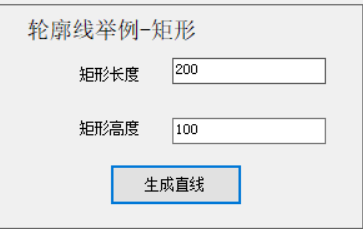
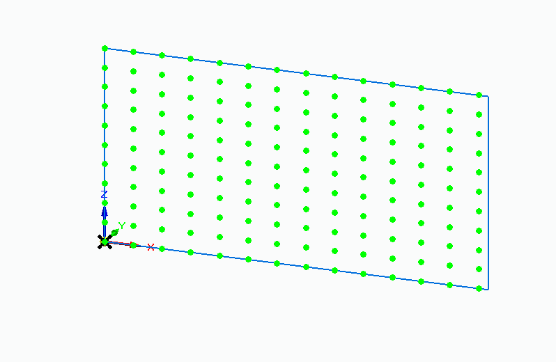
11、画矩形
/**
         * 画矩形
         */
private void button14_Click(object sender, EventArgs e)
{
    if (textBox8.Text == "" || textBox7.Text == "")
    {
        MessageBox.Show("必填项不能为空");
        return;
    }
    //@1 连接solidedge应用
    // Register with OLE to handle concurrency issues on the current thread.
    SolidEdgeCommunity.OleMessageFilter.Register();

    //Connect to or start Solid Edge.这个方法里面的两个参数是开启功能:1、如果未启动就启动一个,2、如果启动了就显示,
    objApp = SolidEdgeCommunity.SolidEdgeUtils.Connect(true, true);

    //创建零件文档
    PartDocument objPartDoc = objApp.Documents.AddPartDocument();

    Profile objProfile = objPartDoc.ProfileSets.Add().Profiles.Add(objPartDoc.RefPlanes.Item(3));

    //获得矩形的输入参数
    double objWidth = double.Parse(textBox8.Text) / 1000;
    double objHeight = double.Parse(textBox7.Text) / 1000;

    RectangularPattern2d objRPattern = objProfile.RectangularPatterns2d.Add(
        OriginX: 0, OriginY: 0,
        Width: objWidth, Height: objHeight,
        Angle: 0,
        OffsetType: PatternOffsetTypeConstants.sePatternFillOffset,
        XCount: 6, YCount: 4,
        XSpace: 0.015, YSpace: 0.01);

    objApp.DoIdle();
    objApp.Visible = true;
}- 核心-RectangularPatterns2d
//获得矩形的输入参数
double objWidth = double.Parse(textBox8.Text) / 1000;
double objHeight = double.Parse(textBox7.Text) / 1000;

RectangularPattern2d objRPattern = objProfile.RectangularPatterns2d.Add(
    OriginX: 0, OriginY: 0,
    Width: objWidth, Height: objHeight,
    Angle: 0,
    OffsetType: PatternOffsetTypeConstants.sePatternFillOffset,
    XCount: 6, YCount: 4,
XSpace: 0.015, YSpace: 0.01);- 结果展示:
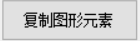
12、复制图形元素
/**
         * 复制图形元素
         */
private void button16_Click(object sender, EventArgs e)
{
    //@1 连接solidedge应用
    // Register with OLE to handle concurrency issues on the current thread.
    SolidEdgeCommunity.OleMessageFilter.Register();

    //Connect to or start Solid Edge.这个方法里面的两个参数是开启功能:1、如果未启动就启动一个,2、如果启动了就显示,
    objApp = SolidEdgeCommunity.SolidEdgeUtils.Connect(true, true);

    //创建零件文档
    PartDocument objPartDoc = objApp.Documents.AddPartDocument();

    Profile objProfile1 = objPartDoc.ProfileSets.Add().Profiles.Add(objPartDoc.RefPlanes.Item(1));

    //原点加半径
    Circle2d circle2D = objProfile1.Circles2d.AddByCenterRadius(0, 0, 0.08);

    //复制圆
    circle2D.Duplicate(XDistance: 0.1);
    circle2D.Duplicate(YDistance: 0.1);
    circle2D.Duplicate(XDistance: 0.1, YDistance: 0.1);

    objApp.DoIdle();
    objApp.Visible = true;
}- 核心代码
//原点加半径
Circle2d circle2D = objProfile1.Circles2d.AddByCenterRadius(0, 0, 0.08);

//复制圆
circle2D.Duplicate(XDistance: 0.1);
circle2D.Duplicate(YDistance: 0.1);
circle2D.Duplicate(XDistance: 0.1, YDistance: 0.1);- 结果展示:
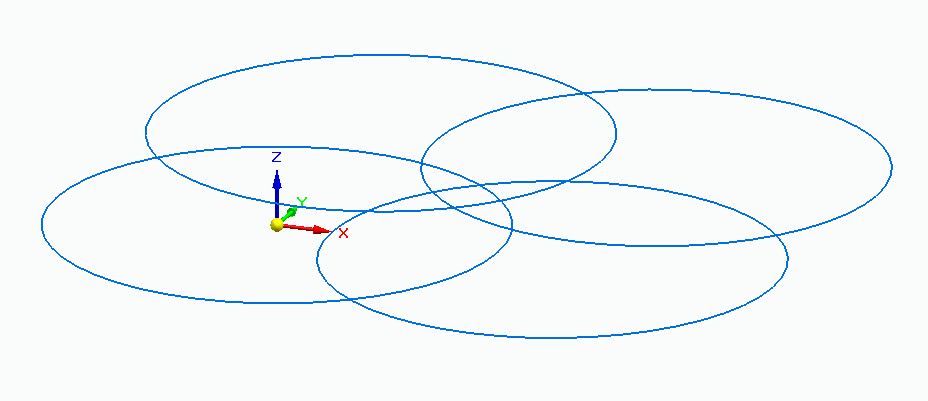
13、创建圆角
/**
         * 创建圆角
         */
private void button18_Click(object sender, EventArgs e)
{
    //@1 连接solidedge应用
    // Register with OLE to handle concurrency issues on the current thread.
    SolidEdgeCommunity.OleMessageFilter.Register();

    //Connect to or start Solid Edge.这个方法里面的两个参数是开启功能:1、如果未启动就启动一个,2、如果启动了就显示,
    objApp = SolidEdgeCommunity.SolidEdgeUtils.Connect(true, true);

    //创建零件文档
    PartDocument objPartDoc = objApp.Documents.AddPartDocument();
    //先创建轮廓对象集合
    Profile profile = objPartDoc.ProfileSets.Add().Profiles.Add(objPartDoc.RefPlanes.Item(1));
    //在轮廓里创建直线,用来画长方形,也可以用其他方法划长方形
    Line2d line1 = profile.Lines2d.AddBy2Points(0, 0, 0.08, 0);
    Line2d line2 = profile.Lines2d.AddBy2Points(0.08, 0, 0.08, 0.06);
    Line2d line3 = profile.Lines2d.AddBy2Points(0.08, 0.06, 0, 0.06);
    Line2d line4 = profile.Lines2d.AddBy2Points(0, 0.06, 0, 0);

    //创建圆弧对象集合后创建倒圆角
    profile.Arcs2d.AddAsFillet(line1, line2, 0.01, 0.05, 0.15);
    profile.Arcs2d.AddAsFillet(line2, line3, 0.01, -0.15, -0.05);
    profile.Arcs2d.AddAsFillet(line3, line4, 0.01, 0.15, 0.05);
    profile.Arcs2d.AddAsFillet(line4, line1, 0.01, 0.05, 0.15);

    objApp.DoIdle();
    objApp.Visible = true;
}- 核心代码
//在轮廓里创建直线,用来画长方形,也可以用其他方法划长方形
Line2d line1 = profile.Lines2d.AddBy2Points(0, 0, 0.08, 0);
Line2d line2 = profile.Lines2d.AddBy2Points(0.08, 0, 0.08, 0.06);
Line2d line3 = profile.Lines2d.AddBy2Points(0.08, 0.06, 0, 0.06);
Line2d line4 = profile.Lines2d.AddBy2Points(0, 0.06, 0, 0);

//创建圆弧对象集合后创建倒圆角
profile.Arcs2d.AddAsFillet(line1, line2, 0.01, 0.05, 0.15);
profile.Arcs2d.AddAsFillet(line2, line3, 0.01, -0.15, -0.05);
profile.Arcs2d.AddAsFillet(line3, line4, 0.01, 0.15, 0.05);
profile.Arcs2d.AddAsFillet(line4, line1, 0.01, 0.05, 0.15);- 结果展示:
14、平行约束
/**
         * 平行约束
         */
private void button17_Click(object sender, EventArgs e)
{
    //@1 连接solidedge应用
    // Register with OLE to handle concurrency issues on the current thread.
    SolidEdgeCommunity.OleMessageFilter.Register();

    //Connect to or start Solid Edge.这个方法里面的两个参数是开启功能:1、如果未启动就启动一个,2、如果启动了就显示,
    objApp = SolidEdgeCommunity.SolidEdgeUtils.Connect(true, true);

    //创建零件文档
    PartDocument objPartDoc = objApp.Documents.AddPartDocument();

    Profile profile = objPartDoc.ProfileSets.Add().Profiles.Add(pRefPlaneDisp: objPartDoc.RefPlanes.Item(1));

    //弄两直线出来
    Line2d line1 = profile.Lines2d.AddBy2Points(-0.03, 0.06, 0.01, 0.04);
    Line2d line2 = profile.Lines2d.AddBy2Points(-0.05, 0.01, 0.05, 0.03);

    Relations2d relations2D = (Relations2d)profile.Relations2d;
    relations2D.AddParallel(line1, line2);

    //垂直一把
    //relations2D.AddVertical(line1);

    objApp.DoIdle();
    objApp.Visible = true;
}- 核心代码
//弄两直线出来
    Line2d line1 = profile.Lines2d.AddBy2Points(-0.03, 0.06, 0.01, 0.04);
    Line2d line2 = profile.Lines2d.AddBy2Points(-0.05, 0.01, 0.05, 0.03);

    Relations2d relations2D = (Relations2d)profile.Relations2d;
relations2D.AddParallel(line1, line2);- 结果展示:
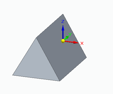
15、画个三角形
/**
         * 画个三角形
         */
private void button19_Click(object sender, EventArgs e)
{
    //@1 连接solidedge应用
    // Register with OLE to handle concurrency issues on the current thread.
    SolidEdgeCommunity.OleMessageFilter.Register();

    //Connect to or start Solid Edge.这个方法里面的两个参数是开启功能:1、如果未启动就启动一个,2、如果启动了就显示,
    objApp = SolidEdgeCommunity.SolidEdgeUtils.Connect(true, true);

    //创建零件文档
    PartDocument objPartDoc = objApp.Documents.AddPartDocument();

    Profile[] objProfiles = new Profile[3];


    ///@创建三棱柱
    ///

    //设置参考面
    objProfiles[1] = objPartDoc.ProfileSets.Add().Profiles.Add(pRefPlaneDisp: objPartDoc.RefPlanes.Item(3));
    Lines2d objLines = objProfiles[1].Lines2d;

    //绘制三角形轮廓线(由三条直线围成)
    objLines.AddBy2Points(0, 0.034, -0.03, -0.017);
    objLines.AddBy2Points(-0.03, -0.017, 0.03, -0.017);
    objLines.AddBy2Points(0.03, -0.017, 0, 0.034);

    //使用AddKeypoint方法,使三条直线闭合
    Relations2d relations2D = (Relations2d)objProfiles[1].Relations2d;
    relations2D.AddKeypoint(objLines.Item(1), (int)KeypointIndexConstants.igLineEnd,
                            objLines.Item(2), (int)KeypointIndexConstants.igLineStart);
    relations2D.AddKeypoint(objLines.Item(2), (int)KeypointIndexConstants.igLineEnd,
                            objLines.Item(3), (int)KeypointIndexConstants.igLineStart);
    relations2D.AddKeypoint(objLines.Item(3), (int)KeypointIndexConstants.igLineEnd,
                            objLines.Item(1), (int)KeypointIndexConstants.igLineStart);

    //检查草图轮廓
    int lngStatus = objProfiles[1].End(ValidationCriteria: ProfileValidationType.igProfileClosed);
    if (lngStatus != 0)
    {
        MessageBox.Show("Progile not closed");
    }

    // Create a new array of profile objects.
    Array profileArray = Array.CreateInstance(typeof(Profile), 1); //创建使用 从零开始的索引、具有指定tppe和长度 的一维数组 这里是创建 SolidEdgePart.Profile 类型的只有一个元素的一个一维数组
    profileArray.SetValue(objProfiles[1], 0); // 将这个数组的唯一元素的只设置为 profile

    Model objModel = objPartDoc.Models.AddFiniteExtrudedProtrusion(
        NumberOfProfiles: profileArray.Length,//指定在创建拉伸体时使用的轮廓的数量的长型
        ProfileArray: profileArray, //包含用于拉伸的轮廓的数组,数组中轮廓的数量必须和numberofprofiles参数指定的参数相等
        ProfilePlaneSide: FeaturePropertyConstants.igRight,// 拉伸的方向,igright是正向,igleft是负向,igsymmetric是双向
        ExtrusionDistance: 0.09);
    //关闭草图
    objProfiles[1].Visible = false;

    objApp.DoIdle();
    objApp.Visible = true;
}- 核心代码
    ///@创建三棱柱
    ///
//绘制三角形轮廓线(由三条直线围成)
    objLines.AddBy2Points(0, 0.034, -0.03, -0.017);
    objLines.AddBy2Points(-0.03, -0.017, 0.03, -0.017);
    objLines.AddBy2Points(0.03, -0.017, 0, 0.034);
//使用AddKeypoint方法,使三条直线闭合
    Relations2d relations2D = (Relations2d)objProfiles[1].Relations2d;
    relations2D.AddKeypoint(objLines.Item(1), (int)KeypointIndexConstants.igLineEnd,
                            objLines.Item(2), (int)KeypointIndexConstants.igLineStart);
    relations2D.AddKeypoint(objLines.Item(2), (int)KeypointIndexConstants.igLineEnd,
                            objLines.Item(3), (int)KeypointIndexConstants.igLineStart);
    relations2D.AddKeypoint(objLines.Item(3), (int)KeypointIndexConstants.igLineEnd,
                            objLines.Item(1), (int)KeypointIndexConstants.igLineStart);


// Create a new array of profile objects.
    Array profileArray = Array.CreateInstance(typeof(Profile), 1); //创建使用 从零开始的索引、具有指定tppe和长度 的一维数组 这里是创建 SolidEdgePart.Profile 类型的只有一个元素的一个一维数组
    profileArray.SetValue(objProfiles[1], 0); // 将这个数组的唯一元素的只设置为 profile

    Model objModel = objPartDoc.Models.AddFiniteExtrudedProtrusion(
        NumberOfProfiles: profileArray.Length,//指定在创建拉伸体时使用的轮廓的数量的长型
        ProfileArray: profileArray, //包含用于拉伸的轮廓的数组,数组中轮廓的数量必须和numberofprofiles参数指定的参数相等
        ProfilePlaneSide: FeaturePropertyConstants.igRight,// 拉伸的方向,igright是正向,igleft是负向,igsymmetric是双向
ExtrusionDistance: 0.09);- 结果展示:
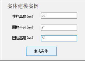
16、生成实体
/**
         * 生成实体
         */
private void button20_Click(object sender, EventArgs e)
{
    //@1 连接solidedge应用
    // Register with OLE to handle concurrency issues on the current thread.
    SolidEdgeCommunity.OleMessageFilter.Register();

    //Connect to or start Solid Edge.这个方法里面的两个参数是开启功能:1、如果未启动就启动一个,2、如果启动了就显示,
    objApp = SolidEdgeCommunity.SolidEdgeUtils.Connect(true, true);

    //创建零件文档
    PartDocument objPartDoc = objApp.Documents.AddPartDocument();

    Profile[] objProfiles = new Profile[3];


    ///@创建三棱柱
    ///

    //设置参考面
    objProfiles[1] = objPartDoc.ProfileSets.Add().Profiles.Add(pRefPlaneDisp: objPartDoc.RefPlanes.Item(3));
    Lines2d objLines = objProfiles[1].Lines2d;

    //绘制三角形轮廓线(由三条直线围成)
    objLines.AddBy2Points(0, 0.034, -0.03, -0.017);
    objLines.AddBy2Points(-0.03, -0.017, 0.03, -0.017);
    objLines.AddBy2Points(0.03, -0.017, 0, 0.034);

    //使用AddKeypoint方法,使三条直线闭合
    Relations2d relations2D = (Relations2d)objProfiles[1].Relations2d;
    relations2D.AddKeypoint(objLines.Item(1), (int)KeypointIndexConstants.igLineEnd,
                            objLines.Item(2), (int)KeypointIndexConstants.igLineStart);
    relations2D.AddKeypoint(objLines.Item(2), (int)KeypointIndexConstants.igLineEnd,
                            objLines.Item(3), (int)KeypointIndexConstants.igLineStart);
    relations2D.AddKeypoint(objLines.Item(3), (int)KeypointIndexConstants.igLineEnd,
                            objLines.Item(1), (int)KeypointIndexConstants.igLineStart);

    //检查草图轮廓
    int lngStatus = objProfiles[1].End(ValidationCriteria: ProfileValidationType.igProfileClosed);
    if (lngStatus != 0)
    {
        MessageBox.Show("objProfiles[1] Progile not closed");
    }

    // Create a new array of profile objects.
    Array profileArray = Array.CreateInstance(typeof(Profile), 1); //创建使用 从零开始的索引、具有指定tppe和长度 的一维数组 这里是创建 SolidEdgePart.Profile 类型的只有一个元素的一个一维数组
    profileArray.SetValue(objProfiles[1], 0); // 将这个数组的唯一元素的只设置为 profile

    Model objModel = objPartDoc.Models.AddFiniteExtrudedProtrusion(
        NumberOfProfiles: profileArray.Length,//指定在创建拉伸体时使用的轮廓的数量的长型
        ProfileArray: profileArray, //包含用于拉伸的轮廓的数组,数组中轮廓的数量必须和numberofprofiles参数指定的参数相等
        ProfilePlaneSide: FeaturePropertyConstants.igRight,// 拉伸的方向,igright是正向,igleft是负向,igsymmetric是双向
        ExtrusionDistance: double.Parse(textBox9.Text) / 1000);
    //关闭草图
    objProfiles[1].Visible = false;


    ///@创建拉伸圆柱
    ///

    Body objBody = (Body)objPartDoc.Models.Item(1).Body;
    //从模型的体对象中检索所有的面
    Faces objFaces = (Faces)objBody.Faces[FeatureTopologyQueryTypeConstants.igQueryAll];
    //从面集中得到第1个面复给对象变量objFace
    Face objFace = (Face)objFaces.Item(1);

    //用对象变量objFace为基面,设置参考平面objRefPln
    //采用平行参考面方法设置(距离设置为0)
    RefPlane objRefPln = objPartDoc.RefPlanes.AddParallelByDistance(
        ParentPlane: objFace,
        Distance: 0,
        NormalSide: ReferenceElementConstants.igNormalSide);

    //设置参考面,并在参考面上绘制圆
    Profile objProf = objPartDoc.ProfileSets.Add().Profiles.Add(objRefPln);
    objProf.Circles2d.AddByCenterRadius(0, 0, double.Parse(textBox10.Text) / 1000);

    //检查草图轮廓是否有效
    lngStatus = objProf.End(ProfileValidationType.igProfileClosed);
    if (lngStatus != 0)
    {
        MessageBox.Show("objProf Profile not closed");
    }
    //创建拉伸特征(圆柱)
    objModel.ExtrudedProtrusions.AddFinite(
        Profile: objProf,
        ProfileSide: FeaturePropertyConstants.igLeft,
        ProfilePlaneSide: FeaturePropertyConstants.igRight,
        Depth: double.Parse(textBox11.Text) / 1000);

    //显示草图轮廓线
    objProf.Visible = true;

    ///@创建拉伸圆柱2
    ///
    //重新搜索对象中所有的面
    objBody = (Body)objPartDoc.Models.Item(1).Body;
    objFaces = (Faces)objBody.Faces[FeatureTopologyQueryTypeConstants.igQueryAll];
    //从面集合中得到第二个面赋值给对象变量objFace1
    Face objFace1 = (Face)objFaces.Item(2);

    //用对象变量objFace1为基面,设置参考平面objRefPln1
    //采用平行参考面方法获得参考面(距离设置为0)
    RefPlane objRefPln1 = objPartDoc.RefPlanes.AddParallelByDistance(
        ParentPlane: objFace1,
        Distance: 0,
        NormalSide: ReferenceElementConstants.igNormalSide);

    //设置参考面,并在参考面上绘制圆
    Profile objProf1 = objPartDoc.ProfileSets.Add().Profiles.Add(objRefPln1);
    objProf1.Circles2d.AddByCenterRadius(0, 0, double.Parse(textBox10.Text) / 1000);
    //检查草图轮廓是否有效
    lngStatus = objProf1.End(ProfileValidationType.igProfileClosed);
    if (lngStatus != 0)
    {
        MessageBox.Show("objProf2 Profile not closed");
    }
    //创建拉伸实体特征
    objModel.ExtrudedProtrusions.AddFinite(
        Profile: objProf1,
        ProfileSide: FeaturePropertyConstants.igLeft,
        ProfilePlaneSide: FeaturePropertyConstants.igRight,
        Depth: double.Parse(textBox11.Text) / 1000);
    //显示草图轮廓线
    objProf.Visible = true;


    ///@创建拉伸圆柱3
    ///
    //重新搜索对象中所有的面
    objBody = (Body)objPartDoc.Models.Item(1).Body;
    objFaces = (Faces)objBody.Faces[FeatureTopologyQueryTypeConstants.igQueryAll];
    //从面集合中得到第二个面赋值给对象变量objFace2
    Face objFace2 = (Face)objFaces.Item(3);

    //用对象变量objFace2为基面,设置参考平面objRefPln2
    //采用平行参考面方法获得参考面(距离设置为0)
    RefPlane objRefPln2 = objPartDoc.RefPlanes.AddParallelByDistance(
        ParentPlane: objFace2,
        Distance: 0,
        NormalSide: ReferenceElementConstants.igNormalSide);

    //设置参考面,并在参考面上绘制圆
    Profile objProf2 = objPartDoc.ProfileSets.Add().Profiles.Add(objRefPln2);
    objProf2.Circles2d.AddByCenterRadius(0, 0, double.Parse(textBox10.Text) / 1000);
    //检查草图轮廓是否有效
    lngStatus = objProf2.End(ProfileValidationType.igProfileClosed);
    if (lngStatus != 0)
    {
        MessageBox.Show("objProf2 Profile not closed");
    }
    //创建拉伸实体特征
    objModel.ExtrudedProtrusions.AddFinite(
        Profile: objProf2,
        ProfileSide: FeaturePropertyConstants.igLeft,
        ProfilePlaneSide: FeaturePropertyConstants.igRight,
        Depth: double.Parse(textBox11.Text) / 1000);
    //显示草图轮廓线
    objProf.Visible = true;

    objApp.DoIdle();
    objApp.Visible = true;
}- 结果展示:
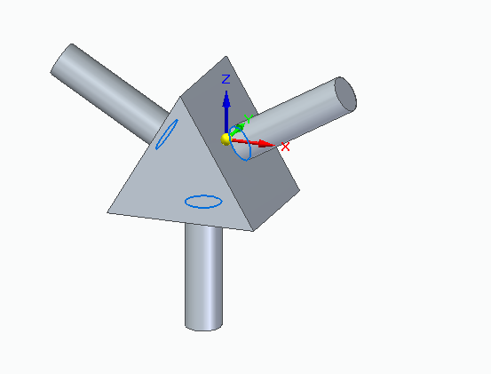
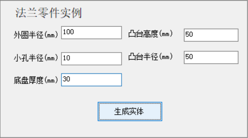
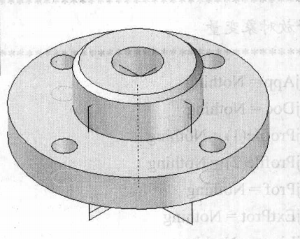
17、法兰零件实例
/**
         * 法兰零件实例
         */
private void button21_Click(object sender, EventArgs e)
{
    //@1 连接solidedge应用
    // Register with OLE to handle concurrency issues on the current thread.
    SolidEdgeCommunity.OleMessageFilter.Register();

    //Connect to or start Solid Edge.这个方法里面的两个参数是开启功能:1、如果未启动就启动一个,2、如果启动了就显示,
    objApp = SolidEdgeCommunity.SolidEdgeUtils.Connect(true, true);

    //创建零件文档
    PartDocument objDoc = objApp.Documents.AddPartDocument();

    ///@声明对象
    ///
    / Create a new array of profile objects.
    Array objRPProfArray = Array.CreateInstance(typeof(Profile), 1); //创建使用 从零开始的索引、具有指定tppe和长度 的一维数组 这里是创建 SolidEdgePart.Profile 类型的只有一个元素的一个一维数组
    //Profile[] objRPProfArray = new Profile[4];
    Array objRPProfArray1 = Array.CreateInstance(typeof(Profile), 1); //创建使用 从零开始的索引、具有指定tppe和长度 的一维数组 这里是创建 SolidEdgePart.Profile 类型的只有一个元素的一个一维数组
    //Profile[] objRPProfArray1 = new Profile[4];
    Array objEdgArr = Array.CreateInstance(typeof(Edge), 1);
    Array objEdgArray = Array.CreateInstance(typeof(Edge), 1);
    Array db1RadiusArray = new Double[2];


    ///@3用旋转填料创建地盘(大圆)
    ///
    //设置参考面
    Profile objRPProfile = objDoc.ProfileSets.Add().Profiles.Add(objDoc.RefPlanes.Item(2));
    //绘制轴线
    objRPProfile.Lines2d.AddBy2Points(0, -0.05, 0, 0.05);
    //设置参考轴
    RefAxis objRPRAxis = (RefAxis)objRPProfile.SetAxisOfRevolution(objRPProfile.Lines2d.Item(1));

    //绘制矩形轮廓线
    objRPProfile.RectangularPatterns2d.Add(
        OriginX: 0, OriginY: 0,
        Width: double.Parse(textBox12.Text) / 1000, Height: double.Parse(textBox13.Text) / 1000,
        Angle: 0, OffsetType: PatternOffsetTypeConstants.sePatternFillOffset,
        XCount: 6, YCount: 4,
        XSpace: 0.015, YSpace: 0.01);
    //检查草图轮廓是否有效
    int lngStatus = 0;
    if (lngStatus != 0)
    {
        MessageBox.Show("objRPProfile Profile for the base feature is self-intersecting");
    }
    //使用旋转填料方法生成特征
    objRPProfArray.SetValue(objRPProfile, 0); // 将这个数组的唯一元素的只设置为 profile
    Model objModel = objDoc.Models.AddFiniteRevolvedProtrusion(
        NumberOfProfiles: objRPProfArray.Length,
        ProfileArray: objRPProfArray,
        ReferenceAxis: objRPRAxis,
        ProfilePlaneSide: FeaturePropertyConstants.igRight,
        AngleofRevolution: 2 * PI);
    //显示草图轮廓线(一般设为隐藏)
    objRPProfile.Visible = false;


    ///@4拉伸除料(在底盘打四个小孔)
    ///
    ///设置参考线
    Profile objProf = objDoc.ProfileSets.Add().Profiles.Add(objDoc.RefPlanes.Item(1));
    //绘制轮廓线
    objProf.Circles2d.AddByCenterRadius(0, 0.08, double.Parse(textBox14.Text) / 1000);
    objProf.Circles2d.AddByCenterRadius(0, -0.08, double.Parse(textBox14.Text) / 1000);
    objProf.Circles2d.AddByCenterRadius(0.08, 0, double.Parse(textBox14.Text) / 1000);
    objProf.Circles2d.AddByCenterRadius(-0.08, 0, double.Parse(textBox14.Text) / 1000);

    //检查轮廓线是否封闭
    lngStatus = objProf.End(ProfileValidationType.igProfileClosed);
    if (lngStatus != 0)
    {
        MessageBox.Show("objProf Profile not closed");
    }
    //使用拉伸除料防范,除料深度为textBox14.Text
    objModel.ExtrudedCutouts.AddFinite(
        Profile: objProf,
        ProfileSide: FeaturePropertyConstants.igLeft,
        ProfilePlaneSide: FeaturePropertyConstants.igRight,
        Depth: double.Parse(textBox13.Text) / 1000);
    //显示草图轮廓线(一般设为隐藏)
    objProf.Visible = false;


    ///@5拉伸填料(创建法兰凸台)
    ///
    ///创建平行参考面
    RefPlane objRefPln1 = objDoc.RefPlanes.AddParallelByDistance(
        ParentPlane: objDoc.RefPlanes.Item(1),
        Distance: 0.02,
        NormalSide: ReferenceElementConstants.igNormalSide);

    //设置参考面
    Profile objProf1 = objDoc.ProfileSets.Add().Profiles.Add(objRefPln1);
    //绘制轮廓线圈
    objProf1.Circles2d.AddByCenterRadius(0, 0, double.Parse(textBox15.Text) / 1000);

    //检查轮廓线是否封闭
    lngStatus = objProf1.End(ProfileValidationType.igProfileClosed);
    if (lngStatus != 0)
    {
        MessageBox.Show("objProf1 Profile not closed");
    }
    objRPProfArray1.SetValue(objProf1, 0);

    //创建拉伸特征。拉伸长度由textBox16.Text定义
    Model objModel1 = objDoc.Models.AddFiniteExtrudedProtrusion(
        NumberOfProfiles: objRPProfArray1.Length,
        ProfileArray: objRPProfArray1,
        ProfilePlaneSide: FeaturePropertyConstants.igRight,
        ExtrusionDistance: double.Parse(textBox16.Text) / 1000);
    //显示草图轮廓线
    objRefPln1.Visible = false;


    ///@6在凸台上做45°倒角
    ///
    ExtrudedProtrusion objExtProt = objModel1.ExtrudedProtrusions.Item(1);
    //检查特性1的所有边赋给边的集合对象变量
    Edges objEdges = (Edges)objExtProt.Edges[FeatureTopologyQueryTypeConstants.igQueryAll];
    //将边存到数组
    objEdgArr.SetValue(objEdges.Item(1), 0);
    //检索特征1的所有面赋给集合对象变量
    Faces objFacs = (Faces)objExtProt.Faces[FeatureTopologyQueryTypeConstants.igQueryAll];

    //创建倒角
    Chamfer objChmfr = objModel.Chamfers.AddSetbackAngle(
        ReferenceFace: objFacs.Item(1),
        NumberOfEdgeSets: objEdgArr.Length,
        EdgeSetArray: objEdgArr,
        SetbackDistance: 0.005,
        Angle: 45 * PI / 180);


    ///@7用旋转除料方式形成中心孔
    ///
    //设置参考面
    Profile objProf11 = objDoc.ProfileSets.Add().Profiles.Add(objDoc.RefPlanes.Item(3));
    //画轮廓线
    objProf11.RectangularPatterns2d.Add(
        OriginX: 0, OriginY: 0,
        Width: 0.02, Height: 0.08,
        Angle: 0, OffsetType: PatternOffsetTypeConstants.sePatternFillOffset,
        XCount: 6, YCount: 4,
        XSpace: 0.015, YSpace: 0.01);

    //设置旋转轴
    Line2d objCutoutLine = objProf11.Lines2d.AddBy2Points(0, -0.05, 0, 0.05);
    RefAxis objcutoutRefAxis = (RefAxis)objProf11.SetAxisOfRevolution(objCutoutLine);

    //使用旋转除料方法打孔
    objModel1.RevolvedCutouts.AddFinite(
        Profile: objProf11,
        RefAxis: objcutoutRefAxis,
        ProfileSide: FeaturePropertyConstants.igLeft,
        ProfilePlaneSide: FeaturePropertyConstants.igRight,
        AngleofRevolution: (2 * PI));
    //隐藏草图轮廓线
    objProf11.Visible = false;

}- 结果展示:
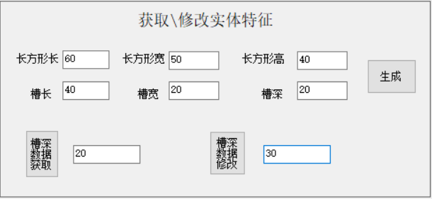
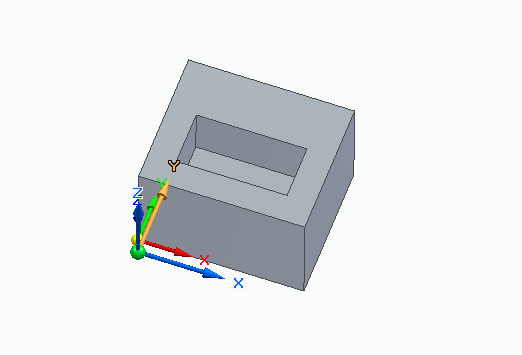
18、生成实体特征-长方体槽
/**
         * 生成实体特征-长方体槽
         */
private void button22_Click(object sender, EventArgs e)
{
    //@1 连接solidedge应用
    // Register with OLE to handle concurrency issues on the current thread.
    SolidEdgeCommunity.OleMessageFilter.Register();

    //Connect to or start Solid Edge.这个方法里面的两个参数是开启功能:1、如果未启动就启动一个,2、如果启动了就显示,
    objApp = SolidEdgeCommunity.SolidEdgeUtils.Connect(true, true);

    //创建零件文档
    PartDocument objDoc = objApp.Documents.AddPartDocument();

    ///@声明对象
    ///
    / Create a new array of profile objects.
    Array objEPProfArray = Array.CreateInstance(typeof(Profile), 1); //创建使用 从零开始的索引、具有指定tppe和长度 的一维数组 这里是创建 SolidEdgePart.Profile 类型的只有一个元素的一个一维数组
    Array db1RadiusArray = new Double[2];

    RefPlane xoy = objDoc.RefPlanes.Item(1);
    RefPlane yoz = objDoc.RefPlanes.Item(2);
    RefPlane xoz = objDoc.RefPlanes.Item(3);

    int lngStatus = 0;


    ///@3拉伸长方体
    ///
    //创建基本特征的轮廓线-矩形
    Profile objEPProfile = objDoc.ProfileSets.Add().Profiles.Add(xoy);
    objEPProfile.RectangularPatterns2d.Add(
        OriginX: 0, OriginY: 0,
        Width: double.Parse(Rect_Length.Text) / 1000, Height: double.Parse(Rect_Width.Text) / 1000,
        Angle: 0, OffsetType: PatternOffsetTypeConstants.sePatternFillOffset,
        XCount: 6, YCount: 4,
        XSpace: 0.015, YSpace: 0.01);

    //轮廓线校验
    lngStatus = objEPProfile.End(ProfileValidationType.igProfileClosed);
    if (lngStatus != 0)
    {
        MessageBox.Show("objEPProfile Profile for the base feature is self-intersecting");
    }

    //创建拉伸
    objEPProfArray.SetValue(objEPProfile, 0);
    Model objModel = objDoc.Models.AddFiniteExtrudedProtrusion(
        NumberOfProfiles: objEPProfArray.Length,
        ProfileArray: objEPProfArray,
        ProfilePlaneSide: FeaturePropertyConstants.igRight,
        ExtrusionDistance: double.Parse(Rect_Height.Text) / 1000);

    objEPProfile.Visible = false;


    ///@4拉伸除料,切出槽
    ///
    if (double.Parse(Rect_Length.Text) > double.Parse(Cut_Length.Text) &&
        double.Parse(Rect_Width.Text) > double.Parse(Cut_Width.Text))
    {
        //建立参考面
        RefPlane objRPParallel = objDoc.RefPlanes.AddParallelByDistance(
            ParentPlane: xoy,
            Distance: double.Parse(Rect_Height.Text) / 1000,
            NormalSide: ReferenceElementConstants.igNormalSide);

        //画槽的轮廓线
        objEPProfile = objDoc.ProfileSets.Add().Profiles.Add(objRPParallel);
        objEPProfile.RectangularPatterns2d.Add(
            OriginX: 0.01, OriginY: 0.01,
            Width: double.Parse(Cut_Length.Text) / 1000, Height: double.Parse(Cut_Width.Text) / 1000,
            Angle: 0, OffsetType: PatternOffsetTypeConstants.sePatternFillOffset,
            XCount: 6, YCount: 4,
            XSpace: 0.015, YSpace: 0.01);

        //创建槽的拉伸除料
        ExtrudedCutout objExtCut = objModel.ExtrudedCutouts.AddFinite(
            Profile: objEPProfile,
            ProfileSide: FeaturePropertyConstants.igLeft,
            ProfilePlaneSide: FeaturePropertyConstants.igLeft,
            Depth: double.Parse(Cut_Height.Text) / 1000);
    }
    else
    {
        MessageBox.Show("槽的长度超出了实体长,请重新输入");
    }
    objEPProfile.Visible = false;

}
//获取槽深
private void button23_Click(object sender, EventArgs e)
{
    //获取当前活动文档
    PartDocument partDocument = (PartDocument)objApp.ActiveDocument;
    //拾取数据
    ExtrudedCutout objcutout = partDocument.Models.Item(1).ExtrudedCutouts.Item(1);

    if (objcutout.ExtentType == FeaturePropertyConstants.igFinite)
    {
        //数据显示
        Old_Depth.Text = (objcutout.Depth * 1000).ToString();
    }

}

/**
         * 修改槽深
         */
private void button24_Click(object sender, EventArgs e)
{
    if (Chg_Depth.Text == "")
    {
        MessageBox.Show("必填项不能为空");
    }
    //获取当前活动文档
    PartDocument partDocument = (PartDocument)objApp.ActiveDocument;
    //修改数据
    ExtrudedCutout objcutout = partDocument.Models.Item(1).ExtrudedCutouts.Item(1);

    if (objcutout.ExtentType == FeaturePropertyConstants.igFinite)
    {
        objcutout.Depth = double.Parse(Chg_Depth.Text) / 1000;
    }
}- 结果展示:
Q.E.D.


 176
176

 被折叠的 条评论
为什么被折叠?
被折叠的 条评论
为什么被折叠?
 到【灌水乐园】发言


