


转自http://blog.163.com/huawei_d/blog/static/2116102572012105105657141/
前言:在大部分情况下,设备的memory和IRQ资源不足够让驱动正常工作。board setup code 会用device 的platform_data域来为设备提供一些额外的资源。嵌入式系统上的设备会频繁地使用一个或者多个时钟,这些时钟因为
节电的原因只有在真正使用的时候才会被打开,系统在启动过程中会为设备分配时钟,可以通过clk_get(dev,clock_name)
来获得需要的时钟。
1 .clk初始化,
采用一个链表把所有用到的时钟结构体链接在一起,该链表的头是clocks,
2. arch/arm/
plat_xxx: 特定平台的通用共用的代码。
平台
arch/arm/
mach_xxx: 完全针对单个板的底层代码。
单个板
3. 从一个时钟产生器(CLOCK generator)中产生的时钟分为两类:
interfaces clocks: 供给接口电路(总线?) xx_ICLK
functional clocks: 供给功能模块 。 xx_FCLK。
clk结构是根据平台自定的结构。
clk模型是平台特定的。
arch/arm/xx平台/clock.h :提供clk结构,及操作接口,宏定义。
arch/arm/xx平台/clock.c :提供操作于该平台的时钟的操作。
mini2440上为了降低电磁干扰配备了12MHz的晶振,如果直接给当做cpu的时钟,那这个s3c2440a就屈才了。幸好cpu内部自带了MPLL将晶振时钟倍频
使得cpu工作在FCLk及AHB总线上的外设工作在HCLK和APB总线上的外设工作在PCLK。当然还配有一个UPLL来产生恒定的48MHZ以支持usb2.0.
①.时钟源选择
在系统复位时检测引脚OM3:OM2,若是0:0,则主时钟源选择外部晶振,usb时钟源选择外部晶振
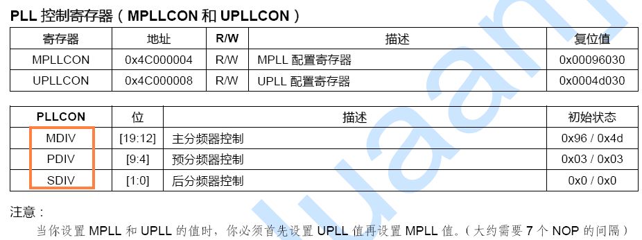
②.MPLLCON main pll control 主时钟寄存器控制
用于设定FCLK和Fin的倍数。
①.时钟源选择
在系统复位时检测引脚OM3:OM2,若是0:0,则主时钟源选择外部晶振,usb时钟源选择外部晶振
②.MPLLCON main pll control 主时钟寄存器控制
用于设定FCLK和Fin的倍数。

Mpll(FCLK) = ( 2 × m × Fin ) / ( p × 2^s )
其中m=MDIV+8, p=PDIV+2, s=SDIV,Fin晶振频率
比如
Fin=12MHz
MDIV=0x7F=127,m=135
PDIV=2,p=4
SDIV=1,s=1
则FCLK=405MHz
注意:系统复位时,必须写一次 MPLLCON UPLLCON ,这样系统才能正常工作。即使不改变其值,即使复位后MPLL UPLL都是使能的,也要写一次,另外还有如下

③.CLKDIVN clock divider control 时钟分频控制寄存器
用于设置 FCLK HCLK PCLK三者的比例
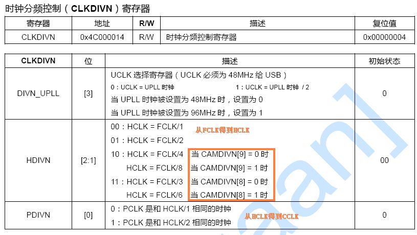
而CAMDIVN如下
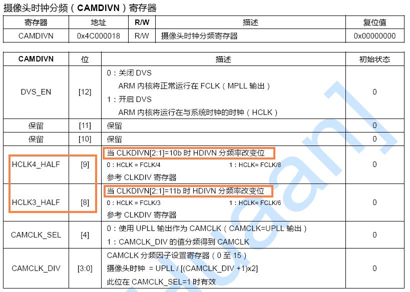
比如
CAMDIVN[8]=0
CAMDIVN[9]=0
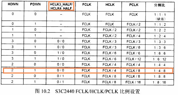
HDIVN=2,则HCLK=FCLK / 4
PDIVN=1,,则PCLK=HCLK / 2
有以下示例,摘自嵌入式linux开发完全手册
2011-12-18
2440的 片内外设 时钟使能控制
linux下将各个片内外设时钟统一管理,组成时钟队列。
arch/arm/plat-s3c24xx/s3c2410-clock.c
- static struct clk init_clocks_disable[] = {
- {
- .name = "nand",
- .id = -1,
- .parent = &clk_h,
- .enable = s3c2410_clkcon_enable,
- .ctrlbit = S3C2410_CLKCON_NAND,
- }, {
- .name = "sdi",
- .id = -1,
- .parent = &clk_p,
- .enable =s3c2410_clkcon_enable,
- .ctrlbit = S3C2410_CLKCON_SDI,
- }, {
- .name = "adc",
- .id = -1,
- .parent = &clk_p,
- .enable = s3c2410_clkcon_enable,
- .ctrlbit = S3C2410_CLKCON_ADC,
- }, {
- .name = "i2c",
- .id = -1,
- .parent = &clk_p,
- .enable = s3c2410_clkcon_enable,
- .ctrlbit = S3C2410_CLKCON_IIC,
- }, {
- .name = "iis",
- .id = -1,
- .parent = &clk_p,
- .enable = s3c2410_clkcon_enable,
- .ctrlbit = S3C2410_CLKCON_IIS,
- }, {
- .name = "spi",
- .id = -1,
- .parent = &clk_p,
- .enable = s3c2410_clkcon_enable,
- .ctrlbit = S3C2410_CLKCON_SPI,
- }
- };
- static struct clk init_clocks[] = {
- {
- .name = "lcd",
- .id = -1,
- .parent = &clk_h,
- .enable = s3c2410_clkcon_enable,
- .ctrlbit = S3C2410_CLKCON_LCDC,
- }, {
- .name = "gpio",
- .id = -1,
- .parent = &clk_p,
- .enable = s3c2410_clkcon_enable,
- .ctrlbit = S3C2410_CLKCON_GPIO,
- }, {
- .name = "usb-host",
- .id = -1,
- .parent = &clk_h,
- .enable = s3c2410_clkcon_enable,
- .ctrlbit = S3C2410_CLKCON_USBH,
- }, {
- .name = "usb-device",
- .id = -1,
- .parent = &clk_h,
- .enable = s3c2410_clkcon_enable,
- .ctrlbit = S3C2410_CLKCON_USBD,
- }, {
- .name = "timers",
- .id = -1,
- .parent = &clk_p,
- .enable = s3c2410_clkcon_enable,
- .ctrlbit = S3C2410_CLKCON_PWMT,
- }, {
- .name = "uart",
- .id = 0,
- .parent = &clk_p,
- .enable = s3c2410_clkcon_enable,
- .ctrlbit = S3C2410_CLKCON_UART0,
- }, {
- .name = "uart",
- .id = 1,
- .parent = &clk_p,
- .enable = s3c2410_clkcon_enable,
- .ctrlbit = S3C2410_CLKCON_UART1,
- }, {
- .name = "uart",
- .id = 2,
- .parent = &clk_p,
- .enable = s3c2410_clkcon_enable,
- .ctrlbit = S3C2410_CLKCON_UART2,
- }, {
- .name = "rtc",
- .id = -1,
- .parent = &clk_p,
- .enable = s3c2410_clkcon_enable,
- .ctrlbit = S3C2410_CLKCON_RTC,
- }, {
- .name = "watchdog",
- .id = -1,
- .parent = &clk_p,
- .ctrlbit = 0,
- }, {
- .name = "usb-bus-host",
- .id = -1,
- .parent = &clk_usb_bus,
- }, {
- .name = "usb-bus-gadget",
- .id = -1,
- .parent = &clk_usb_bus,
- },
- };
- //在需要操作各个外设的时钟时,就调用用内核提供的各个函数即可。如摘自mini2440_adc.c
- static struct clk *adc_clock;
- adc_clock = clk_get(NULL, "adc");//获取时钟
- if (!adc_clock) {
- printk(KERN_ERR "failed to get adc clock source\n");
- return -ENOENT;
- }
- clk_enable(adc_clock);//使能时钟
- //在不需要时,禁止掉
- if (adc_clock) {
- clk_disable(adc_clock);//禁止时钟
- clk_put(adc_clock);
- adc_clock = NULL;//源码下是一个空操作,可能是预留
- }
adc_clock = clk_get(NULL, "adc");
if (!adc_clock) {
printk(KERN_ERR "failed to get adc clock source\n");
return -ENOENT;
}
clk_use(adc_clock);
clk_enable(adc_clock);
上面的这段代码是touchscreen的驱动中的一段,我不清楚,所以去学学系统各个模块时钟的使用方式。
在系统的初始化的时候,看见过,但是忘了,在回顾一下。
***********************************************************************
if (!adc_clock) {
printk(KERN_ERR "failed to get adc clock source\n");
return -ENOENT;
}
clk_use(adc_clock);
clk_enable(adc_clock);
上面的这段代码是touchscreen的驱动中的一段,我不清楚,所以去学学系统各个模块时钟的使用方式。
在系统的初始化的时候,看见过,但是忘了,在回顾一下。
***********************************************************************
**********************************************************
那是在paging_init()中调用了 mdesc->map_io(),
void __init sbc2440_map_io(void)
{
s3c24xx_init_io(sbc2440_iodesc, ARRAY_SIZE(sbc2440_iodesc));
s3c24xx_init_clocks(12000000); //这个是系统各个部分始终初始化的起点
s3c24xx_init_uarts(sbc2440_uartcfgs, ARRAY_SIZE(sbc2440_uartcfgs));
s3c24xx_set_board(&sbc2440_board);
s3c_device_nand.dev.platform_data = &bit_nand_info;
}
跟 cpu_table 有关,拷贝过来
/ * table of supported CPUs */
static const char name_s3c2410[] = "S3C2410";
static const char name_s3c2440[] = "S3C2440";
static const char name_s3c2410a[] = "S3C2410A";
static const char name_s3c2440a[] = "S3C2440A";
static struct cpu_table cpu_ids[] __initdata = {
{
.idcode = 0x32410000,
.idmask = 0xffffffff,
.map_io = s3c2410_map_io,
.init_clocks = s3c2410_init_clocks,
.init_uarts = s3c2410_init_uarts,
.init = s3c2410_init,
.name = name_s3c2410
},
{
.idcode = 0x32410002,
.idmask = 0xffffffff,
.map_io = s3c2410_map_io,
.init_clocks = s3c2410_init_clocks,
.init_uarts = s3c2410_init_uarts,
.init = s3c2410_init,
.name = name_s3c2410a
},
{
.idcode = 0x32440000,
.idmask = 0xffffffff,
.map_io = s3c2440_map_io,
.init_clocks = s3c2440_init_clocks,
.init_uarts = s3c2440_init_uarts,
.init = s3c2440_init,
.name = name_s3c2440
},
{
.idcode = 0x32440001,
.idmask = 0xffffffff,
.map_io = s3c2440_map_io,
.init_clocks = s3c2440_init_clocks,
.init_uarts = s3c2440_init_uarts,
.init = s3c2440_init,
.name = name_s3c2440a
}
};
和时钟相关的调用路径: 在 s3c24xx_init_clocks () -> (cpu->init_clocks)(xtal)-> s3c24xx_setup_clocks()
这个 s3c24xx_setup_clocks()注册了系统的所有时钟 ,仔细看看它。
在这个函数被调用之前,代码已经 根据 S3C2410_MPLLCON,S3C2410_CLKDIVN寄存器 和 晶振 的频率计算出了
fclk,hclk,pclk ,他们应该分别是400M,100M,50M。
struct clk {
struct list_head list;
struct module *owner;
struct clk *parent;
const char *name;
int id;
atomic_t used;
unsigned long rate;
unsigned long ctrlbit;
int (*enable)(struct clk *, int enable);
};
clk数据结构是系统中 时钟的抽象 ,它 用list串成一个双向链表 ,在这个clocks链表里的clk结构,说明是系统中已经注册的,
parent表示他的来源,f,h,p之一 , name是寻找到某个clk的唯一标识 。enable是面向对象的思想的体现,不过,这里
没有用到,只是全部被填充为 s3c24xx_clkcon_enable()。
/* clock information */
static LIST_HEAD(clocks);
static DECLARE_MUTEX(clocks_sem);
/* clock definitions */
static struct clk init_clocks[] = {
{ .name = "nand",
.id = -1,
.parent = &clk_h,
.enable = s3c24xx_clkcon_enable,
.ctrlbit = S3C2410_CLKCON_NAND
},
{ .name = "lcd",
.id = -1,
.parent = &clk_h,
.enable = s3c24xx_clkcon_enable,
.ctrlbit = S3C2410_CLKCON_LCDC
},
{ .name = "usb-host",
.id = -1,
.parent = &clk_h,
.enable = s3c24xx_clkcon_enable,
.ctrlbit = S3C2410_CLKCON_USBH
},
{ .name = "usb-device",
.id = -1,
/*.parent = &clk_h, */
.parent = &clk_xtal,
.enable = s3c24xx_clkcon_enable,
.ctrlbit = S3C2410_CLKCON_USBD
},
{ .name = "timers",
.id = -1,
.parent = &clk_p,
.enable = s3c24xx_clkcon_enable,
.ctrlbit = S3C2410_CLKCON_PWMT
},
{ .name = "sdi",
.id = -1,
.parent = &clk_p,
.enable = s3c24xx_clkcon_enable,
.ctrlbit = S3C2410_CLKCON_SDI
},
{ .name = "uart",
.id = 0 ,
.parent = &clk_p,
.enable = s3c24xx_clkcon_enable,
.ctrlbit = S3C2410_CLKCON_UART0
},
{ .name = "uart",
.id = 1 ,
.parent = &clk_p,
.enable = s3c24xx_clkcon_enable,
.ctrlbit = S3C2410_CLKCON_UART1
},
{ .name = "uart",
.id = 2 ,
.parent = &clk_p,
.enable = s3c24xx_clkcon_enable,
.ctrlbit = S3C2410_CLKCON_UART2
},
{ .name = "gpio",
.id = -1,
.parent = &clk_p,
.enable = s3c24xx_clkcon_enable,
.ctrlbit = S3C2410_CLKCON_GPIO
},
{ .name = "rtc",
.id = -1,
.parent = &clk_p,
.enable = s3c24xx_clkcon_enable,
.ctrlbit = S3C2410_CLKCON_RTC
},
{ .name = "adc",
.id = -1,
.parent = &clk_p,
.enable = s3c24xx_clkcon_enable,
.ctrlbit = S3C2410_CLKCON_ADC
},
{ .name = "i2c",
.id = -1,
.parent = &clk_p,
.enable = s3c24xx_clkcon_enable,
.ctrlbit = S3C2410_CLKCON_IIC
},
{ .name = "iis",
.id = -1,
.parent = &clk_p,
.enable = s3c24xx_clkcon_enable,
.ctrlbit = S3C2410_CLKCON_IIS
},
{ .name = "spi",
.id = -1,
.parent = &clk_p,
.enable = s3c24xx_clkcon_enable,
.ctrlbit = S3C2410_CLKCON_SPI
},
{ .name = "watchdog",
.id = -1,
.parent = &clk_p,
.ctrlbit = 0
}
};
仔细看 ,usb-device 的parent有些特别,watchdog没有enable,只有uart才有id,其他的id都是-1 。
下面可以看 s3c24xx_setup_clocks()了,像所注视的那样,它初始化了所有的时钟, 其实是注册到clocks链表里面,以后可以从clocks
链表中找到。
/* initalise all the clocks */
int __init s3c24xx_setup_clocks(unsigned long xtal,
unsigned long fclk,
unsigned long hclk,
unsigned long pclk)
{
struct clk *clkp = init_clocks;
int ptr;
int ret;
printk(KERN_INFO "S3C2410 Clocks, (c) 2004 Simtec Electronics\n");
/* initialise the main system clocks */
clk_xtal.rate = xtal;
clk_h.rate = hclk;
clk_p.rate = pclk;
clk_f.rate = fclk;
上面的时钟是祖宗级别的,他们的频率已经被确定了。
分别代表晶震12Mhz,arm核400M,h总线100M,p总线50M。
/* it looks like just setting the register here is not good
* enough, and causes the odd hang at initial boot time, so
* do all of them indivdually.
*
* I think disabling the LCD clock if the LCD is active is
* very dangerous, and therefore the bootloader should be
* careful to not enable the LCD clock if it is not needed.
*
* and of course, this looks neater
*/
s3c24xx_clk_enable(S3C2410_CLKCON_NAND, 0); // ghcstop: disable? ==> enable
s3c24xx_clk_enable(S3C2410_CLKCON_USBH, 0);
s3c24xx_clk_enable(S3C2410_CLKCON_USBD, 0);
s3c24xx_clk_enable(S3C2410_CLKCON_ADC, 0);
s3c24xx_clk_enable(S3C2410_CLKCON_IIC, 0);
s3c24xx_clk_enable(S3C2410_CLKCON_SPI, 0);
//s3c24xx_clk_enable(S3C2410_CLKCON_IIS, 1); // default value is 1 ==> enable
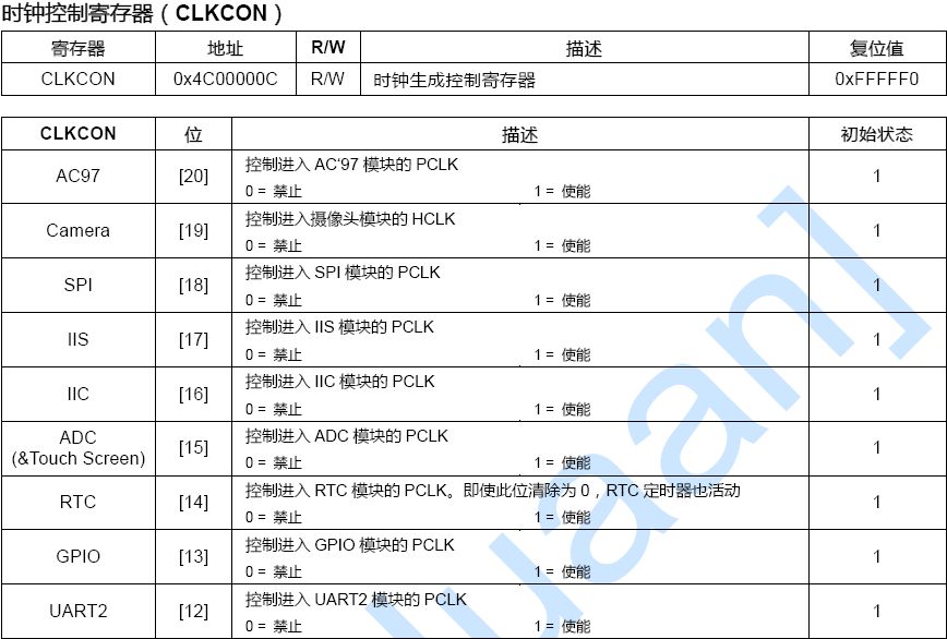
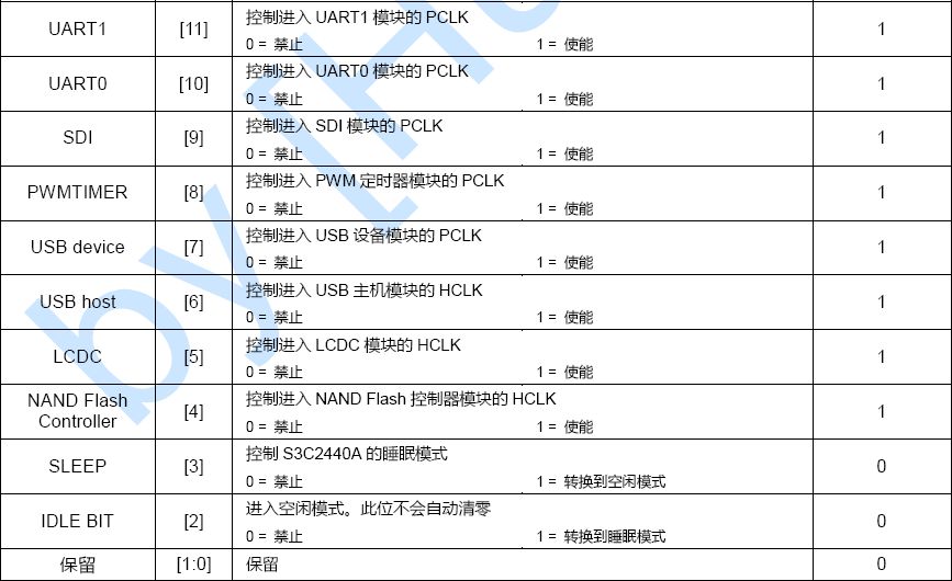
s3c24xx_clk_enable 用来使能/禁止系统对某个模块供应时钟 ,他操作的 对象是CLKCON ,这个寄存器的bit[4~20]每位代表
了系统中的一个模块的时钟供应情况,要么使能,要么禁止。 bit[2~3]分别代表idle和sleep模式,所以s3c24xx_clk_enable
总是去擦出这两个bit位。 然后 根据第2个参数去打开(1)/禁止(0)对某个模块的时钟供应 。
显然,上面的操作都是禁止时钟供应的,包括nand,usbhost,usbdevice,adc,iic,spi。
/* assume uart clocks are correctly setup */
/* register our clocks */
if (s3c24xx_register_clock(&clk_xtal) < 0)
printk(KERN_ERR "failed to register master xtal\n");
if (s3c24xx_register_clock(&clk_f) < 0)
printk(KERN_ERR "failed to register cpu fclk\n");
if (s3c24xx_register_clock(&clk_h) < 0)
printk(KERN_ERR "failed to register cpu hclk\n");
if (s3c24xx_register_clock(&clk_p) < 0)
printk(KERN_ERR "failed to register cpu pclk\n");
s3c24xx_register_clock用于注册这个时钟到clocks链表, 他还设置clk的owner成员为内核模块所拥有,
并且设置clk->used原子型结构为没有被使用(0),然后根据clk->enable有无初始值,为没有初始值的设置一个
哑clk_null_enable,上面的四个base clock都是不能被关闭的,所以他们的clk->enable成员都是clk_null_enable
/* register clocks from clock array */
for (ptr = 0; ptr < ARRAY_SIZE(init_clocks); ptr++, clkp++) {
ret = s3c24xx_register_clock (clkp);
if (ret < 0) {
printk(KERN_ERR "Failed to register clock %s (%d)\n",
clkp->name, ret);
}
}
上面完成了系统其他部分时钟初始化,当然这部分才是我们关心的内容, 这些模块的时钟源都来自base clock 。
其中watchdog没有enable成员,不能被关闭。
return 0;
}//s3c24xx_setup_clocks()end
下面是四个系统的基本时钟,clk_xtal代表晶震。
他们的rate都被上面的函数确定了,而其他部分的时钟还没有rate呢。
/* base clocks */
static struct clk clk_xtal = {
.name = "xtal",
.id = -1,
.rate = 0,
.parent = NULL,
.ctrlbit = 0,
};
static struct clk clk_f = {
.name = "fclk",
.id = -1,
.rate = 0,
.parent = NULL,
.ctrlbit = 0,
};
static struct clk clk_h = {
.name = "hclk",
.id = -1,
.rate = 0,
.parent = NULL,
.ctrlbit = 0,
};
static struct clk clk_p = {
.name = "pclk",
.id = -1,
.rate = 0,
.parent = NULL,
.ctrlbit = 0,
};
宏THIS_MODULE,它的定义如下是#define THIS_MODULE (&__this_module),__this_module是一个struct module变量,
代表当前模块,跟current有几分相似。可以通过THIS_MODULE宏来引用模块的struct module结构
那是在paging_init()中调用了 mdesc->map_io(),
void __init sbc2440_map_io(void)
{
s3c24xx_init_io(sbc2440_iodesc, ARRAY_SIZE(sbc2440_iodesc));
s3c24xx_init_clocks(12000000); //这个是系统各个部分始终初始化的起点
s3c24xx_init_uarts(sbc2440_uartcfgs, ARRAY_SIZE(sbc2440_uartcfgs));
s3c24xx_set_board(&sbc2440_board);
s3c_device_nand.dev.platform_data = &bit_nand_info;
}
跟 cpu_table 有关,拷贝过来
/ * table of supported CPUs */
static const char name_s3c2410[] = "S3C2410";
static const char name_s3c2440[] = "S3C2440";
static const char name_s3c2410a[] = "S3C2410A";
static const char name_s3c2440a[] = "S3C2440A";
static struct cpu_table cpu_ids[] __initdata = {
{
.idcode = 0x32410000,
.idmask = 0xffffffff,
.map_io = s3c2410_map_io,
.init_clocks = s3c2410_init_clocks,
.init_uarts = s3c2410_init_uarts,
.init = s3c2410_init,
.name = name_s3c2410
},
{
.idcode = 0x32410002,
.idmask = 0xffffffff,
.map_io = s3c2410_map_io,
.init_clocks = s3c2410_init_clocks,
.init_uarts = s3c2410_init_uarts,
.init = s3c2410_init,
.name = name_s3c2410a
},
{
.idcode = 0x32440000,
.idmask = 0xffffffff,
.map_io = s3c2440_map_io,
.init_clocks = s3c2440_init_clocks,
.init_uarts = s3c2440_init_uarts,
.init = s3c2440_init,
.name = name_s3c2440
},
{
.idcode = 0x32440001,
.idmask = 0xffffffff,
.map_io = s3c2440_map_io,
.init_clocks = s3c2440_init_clocks,
.init_uarts = s3c2440_init_uarts,
.init = s3c2440_init,
.name = name_s3c2440a
}
};
和时钟相关的调用路径: 在 s3c24xx_init_clocks () -> (cpu->init_clocks)(xtal)-> s3c24xx_setup_clocks()
这个 s3c24xx_setup_clocks()注册了系统的所有时钟 ,仔细看看它。
在这个函数被调用之前,代码已经 根据 S3C2410_MPLLCON,S3C2410_CLKDIVN寄存器 和 晶振 的频率计算出了
fclk,hclk,pclk ,他们应该分别是400M,100M,50M。
struct clk {
struct list_head list;
struct module *owner;
struct clk *parent;
const char *name;
int id;
atomic_t used;
unsigned long rate;
unsigned long ctrlbit;
int (*enable)(struct clk *, int enable);
};
clk数据结构是系统中 时钟的抽象 ,它 用list串成一个双向链表 ,在这个clocks链表里的clk结构,说明是系统中已经注册的,
parent表示他的来源,f,h,p之一 , name是寻找到某个clk的唯一标识 。enable是面向对象的思想的体现,不过,这里
没有用到,只是全部被填充为 s3c24xx_clkcon_enable()。
/* clock information */
static LIST_HEAD(clocks);
static DECLARE_MUTEX(clocks_sem);
/* clock definitions */
static struct clk init_clocks[] = {
{ .name = "nand",
.id = -1,
.parent = &clk_h,
.enable = s3c24xx_clkcon_enable,
.ctrlbit = S3C2410_CLKCON_NAND
},
{ .name = "lcd",
.id = -1,
.parent = &clk_h,
.enable = s3c24xx_clkcon_enable,
.ctrlbit = S3C2410_CLKCON_LCDC
},
{ .name = "usb-host",
.id = -1,
.parent = &clk_h,
.enable = s3c24xx_clkcon_enable,
.ctrlbit = S3C2410_CLKCON_USBH
},
{ .name = "usb-device",
.id = -1,
/*.parent = &clk_h, */
.parent = &clk_xtal,
.enable = s3c24xx_clkcon_enable,
.ctrlbit = S3C2410_CLKCON_USBD
},
{ .name = "timers",
.id = -1,
.parent = &clk_p,
.enable = s3c24xx_clkcon_enable,
.ctrlbit = S3C2410_CLKCON_PWMT
},
{ .name = "sdi",
.id = -1,
.parent = &clk_p,
.enable = s3c24xx_clkcon_enable,
.ctrlbit = S3C2410_CLKCON_SDI
},
{ .name = "uart",
.id = 0 ,
.parent = &clk_p,
.enable = s3c24xx_clkcon_enable,
.ctrlbit = S3C2410_CLKCON_UART0
},
{ .name = "uart",
.id = 1 ,
.parent = &clk_p,
.enable = s3c24xx_clkcon_enable,
.ctrlbit = S3C2410_CLKCON_UART1
},
{ .name = "uart",
.id = 2 ,
.parent = &clk_p,
.enable = s3c24xx_clkcon_enable,
.ctrlbit = S3C2410_CLKCON_UART2
},
{ .name = "gpio",
.id = -1,
.parent = &clk_p,
.enable = s3c24xx_clkcon_enable,
.ctrlbit = S3C2410_CLKCON_GPIO
},
{ .name = "rtc",
.id = -1,
.parent = &clk_p,
.enable = s3c24xx_clkcon_enable,
.ctrlbit = S3C2410_CLKCON_RTC
},
{ .name = "adc",
.id = -1,
.parent = &clk_p,
.enable = s3c24xx_clkcon_enable,
.ctrlbit = S3C2410_CLKCON_ADC
},
{ .name = "i2c",
.id = -1,
.parent = &clk_p,
.enable = s3c24xx_clkcon_enable,
.ctrlbit = S3C2410_CLKCON_IIC
},
{ .name = "iis",
.id = -1,
.parent = &clk_p,
.enable = s3c24xx_clkcon_enable,
.ctrlbit = S3C2410_CLKCON_IIS
},
{ .name = "spi",
.id = -1,
.parent = &clk_p,
.enable = s3c24xx_clkcon_enable,
.ctrlbit = S3C2410_CLKCON_SPI
},
{ .name = "watchdog",
.id = -1,
.parent = &clk_p,
.ctrlbit = 0
}
};
仔细看 ,usb-device 的parent有些特别,watchdog没有enable,只有uart才有id,其他的id都是-1 。
下面可以看 s3c24xx_setup_clocks()了,像所注视的那样,它初始化了所有的时钟, 其实是注册到clocks链表里面,以后可以从clocks
链表中找到。
/* initalise all the clocks */
int __init s3c24xx_setup_clocks(unsigned long xtal,
unsigned long fclk,
unsigned long hclk,
unsigned long pclk)
{
struct clk *clkp = init_clocks;
int ptr;
int ret;
printk(KERN_INFO "S3C2410 Clocks, (c) 2004 Simtec Electronics\n");
/* initialise the main system clocks */
clk_xtal.rate = xtal;
clk_h.rate = hclk;
clk_p.rate = pclk;
clk_f.rate = fclk;
上面的时钟是祖宗级别的,他们的频率已经被确定了。
分别代表晶震12Mhz,arm核400M,h总线100M,p总线50M。
/* it looks like just setting the register here is not good
* enough, and causes the odd hang at initial boot time, so
* do all of them indivdually.
*
* I think disabling the LCD clock if the LCD is active is
* very dangerous, and therefore the bootloader should be
* careful to not enable the LCD clock if it is not needed.
*
* and of course, this looks neater
*/
s3c24xx_clk_enable(S3C2410_CLKCON_NAND, 0); // ghcstop: disable? ==> enable
s3c24xx_clk_enable(S3C2410_CLKCON_USBH, 0);
s3c24xx_clk_enable(S3C2410_CLKCON_USBD, 0);
s3c24xx_clk_enable(S3C2410_CLKCON_ADC, 0);
s3c24xx_clk_enable(S3C2410_CLKCON_IIC, 0);
s3c24xx_clk_enable(S3C2410_CLKCON_SPI, 0);
//s3c24xx_clk_enable(S3C2410_CLKCON_IIS, 1); // default value is 1 ==> enable
s3c24xx_clk_enable 用来使能/禁止系统对某个模块供应时钟 ,他操作的 对象是CLKCON ,这个寄存器的bit[4~20]每位代表
了系统中的一个模块的时钟供应情况,要么使能,要么禁止。 bit[2~3]分别代表idle和sleep模式,所以s3c24xx_clk_enable
总是去擦出这两个bit位。 然后 根据第2个参数去打开(1)/禁止(0)对某个模块的时钟供应 。
显然,上面的操作都是禁止时钟供应的,包括nand,usbhost,usbdevice,adc,iic,spi。
/* assume uart clocks are correctly setup */
/* register our clocks */
if (s3c24xx_register_clock(&clk_xtal) < 0)
printk(KERN_ERR "failed to register master xtal\n");
if (s3c24xx_register_clock(&clk_f) < 0)
printk(KERN_ERR "failed to register cpu fclk\n");
if (s3c24xx_register_clock(&clk_h) < 0)
printk(KERN_ERR "failed to register cpu hclk\n");
if (s3c24xx_register_clock(&clk_p) < 0)
printk(KERN_ERR "failed to register cpu pclk\n");
s3c24xx_register_clock用于注册这个时钟到clocks链表, 他还设置clk的owner成员为内核模块所拥有,
并且设置clk->used原子型结构为没有被使用(0),然后根据clk->enable有无初始值,为没有初始值的设置一个
哑clk_null_enable,上面的四个base clock都是不能被关闭的,所以他们的clk->enable成员都是clk_null_enable
/* register clocks from clock array */
for (ptr = 0; ptr < ARRAY_SIZE(init_clocks); ptr++, clkp++) {
ret = s3c24xx_register_clock (clkp);
if (ret < 0) {
printk(KERN_ERR "Failed to register clock %s (%d)\n",
clkp->name, ret);
}
}
上面完成了系统其他部分时钟初始化,当然这部分才是我们关心的内容, 这些模块的时钟源都来自base clock 。
其中watchdog没有enable成员,不能被关闭。
return 0;
}//s3c24xx_setup_clocks()end
下面是四个系统的基本时钟,clk_xtal代表晶震。
他们的rate都被上面的函数确定了,而其他部分的时钟还没有rate呢。
/* base clocks */
static struct clk clk_xtal = {
.name = "xtal",
.id = -1,
.rate = 0,
.parent = NULL,
.ctrlbit = 0,
};
static struct clk clk_f = {
.name = "fclk",
.id = -1,
.rate = 0,
.parent = NULL,
.ctrlbit = 0,
};
static struct clk clk_h = {
.name = "hclk",
.id = -1,
.rate = 0,
.parent = NULL,
.ctrlbit = 0,
};
static struct clk clk_p = {
.name = "pclk",
.id = -1,
.rate = 0,
.parent = NULL,
.ctrlbit = 0,
};
宏THIS_MODULE,它的定义如下是#define THIS_MODULE (&__this_module),__this_module是一个struct module变量,
代表当前模块,跟current有几分相似。可以通过THIS_MODULE宏来引用模块的struct module结构
好了,回头看看让我晕的函数。
adc_clock = clk_get(NULL, "adc");
if (!adc_clock) {
printk(KERN_ERR "failed to get adc clock source\n");
return -ENOENT;
}
clk_use(adc_clock);
clk_enable(adc_clock);
上面涉及到3个函数,分别是 clk_get,clk_use,clk_enable()。
其中clk_get()的主要代码如下:
list_for_each_entry(p, &clocks, list) {
if (p->id == -1 && strcmp(id, p->name) == 0 &&
try_module_get(p->owner)) {
clk = p;
break;
}
}
看到了吧,不再 clocks这个时钟链表 里的时钟配置是不会被看到的,这都是s3c24xx_register_clock()函数的功劳,
然后他 根据名字,找到对应的时钟结构 ,比如根据"adc"找到adc的clk结构,然后增加对这个模块的使用计数,最后返回
这个找到的clk指针。
clk_use()很简单,只是单纯的增加本时钟的使用
int clk_use(struct clk *clk)
{
atomic_inc(&clk->used);
return 0;
}
在看时钟打开函数,
clk_enable(adc_clock)
int clk_enable(struct clk *clk)
{
if (IS_ERR(clk))
return -EINVAL;
return (clk->enable)(clk, 1) ;
}
这里就体现出了面向对象的思想了, 其中watchdog,四个基本的时钟是没有打开关闭的 。
当然这个函数也是最主要的操作,他 包含了对寄存器CLKCON的操作 。


 619
619


 被折叠的 条评论
为什么被折叠?
被折叠的 条评论
为什么被折叠?
 到【灌水乐园】发言


