


一、 STLINK检查
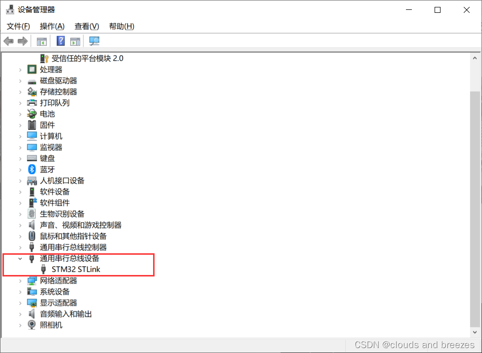
插入stlink检查驱动是否安装好
设备前未有感叹号,驱动安装成功。
二、建立工程文件
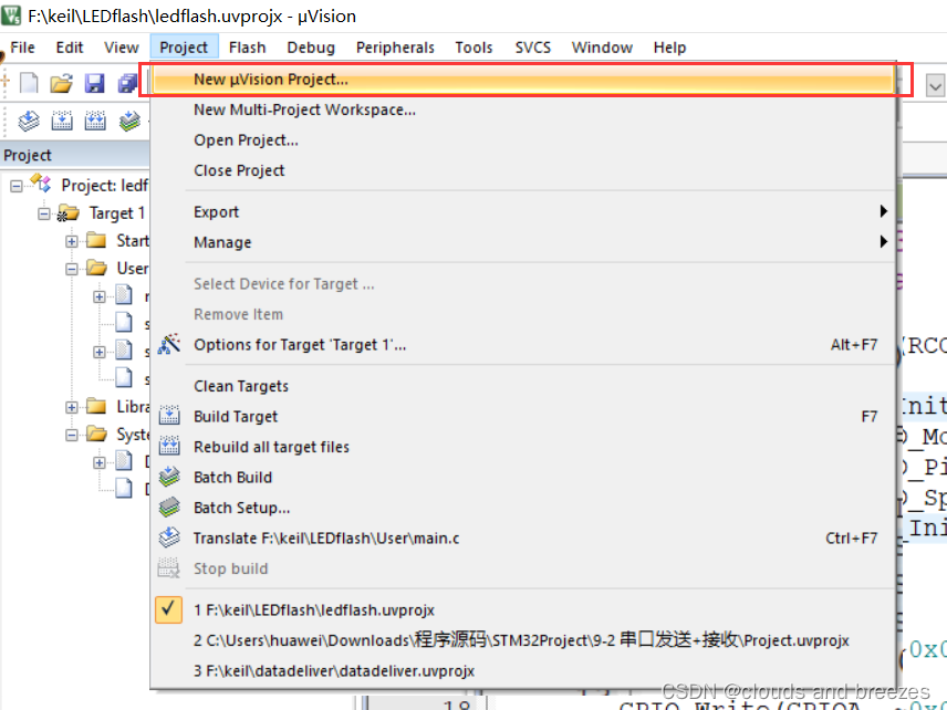
2.1 新建项目
创建项目
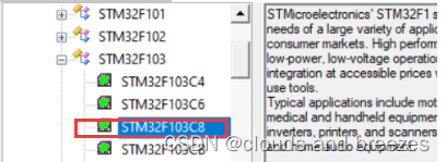
选择STM32F103C8开发板
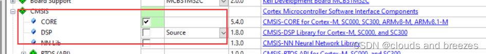
创建项目出现弹窗,勾选core项
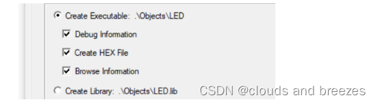
在output里选择create hex file
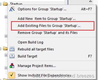
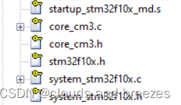
加入启动文件
2.2 写入代码
1.delay函数
#include "stm32f10x.h"

/**
  * @brief  微秒级延时
  * @param  xus 延时时长,范围:0~233015
  * @retval 无
  */
void Delay_us(uint32_t xus)
{
	SysTick->LOAD = 72 * xus;				//设置定时器重装值
	SysTick->VAL = 0x00;					//清空当前计数值
	SysTick->CTRL = 0x00000005;				//设置时钟源为HCLK,启动定时器
	while(!(SysTick->CTRL & 0x00010000));	//等待计数到0
	SysTick->CTRL = 0x00000004;				//关闭定时器
}

/**
  * @brief  毫秒级延时
  * @param  xms 延时时长,范围:0~4294967295
  * @retval 无
  */
void Delay_ms(uint32_t xms)
{
	while(xms--)
	{
		Delay_us(1000);
	}
}

/**
  * @brief  秒级延时
  * @param  xs 延时时长,范围:0~4294967295
  * @retval 无
  */
void Delay_s(uint32_t xs)
{
	while(xs--)
	{
		Delay_ms(1000);
	}
}
2.delay函数头文件
#ifndef __DELAY_H
#define __DELAY_H
#include "stm32f10x.h"
void Delay_us(uint32_t us);
void Delay_ms(uint32_t ms);
void Delay_s(uint32_t  ps);

#endif
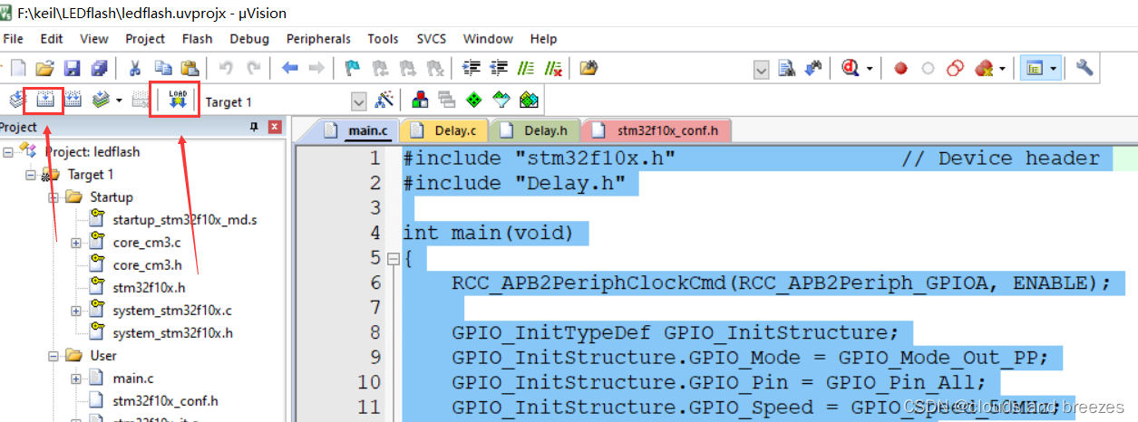
3.main函数
#include "stm32f10x.h"                  // Device header
#include "Delay.h"

int main(void)
{
	RCC_APB2PeriphClockCmd(RCC_APB2Periph_GPIOA, ENABLE);

	GPIO_InitTypeDef GPIO_InitStructure;
	GPIO_InitStructure.GPIO_Mode = GPIO_Mode_Out_PP;
	GPIO_InitStructure.GPIO_Pin = GPIO_Pin_All;
	GPIO_InitStructure.GPIO_Speed = GPIO_Speed_50MHz;
	GPIO_Init(GPIOA, &GPIO_InitStructure);

	while (1)
	{
		GPIO_Write(GPIOA, ~0x0001);	//0000 0000 0000 0001
		Delay_ms(500);
		GPIO_Write(GPIOA, ~0x0002);	//0000 0000 0000 0010
		Delay_ms(500);
		GPIO_Write(GPIOA, ~0x0004);	//0000 0000 0000 0100
		Delay_ms(500);

	}
}
三、写入代码,烧录
3.1 STlink环境配置
-
修改
Define,和Include Paths,勾选c99Mode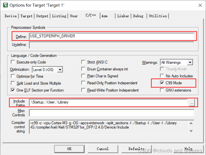
-
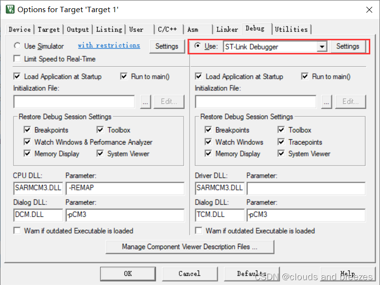
选择
ST-Link Debugger并进入setting
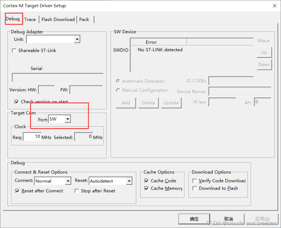
-
Target Com选择SW
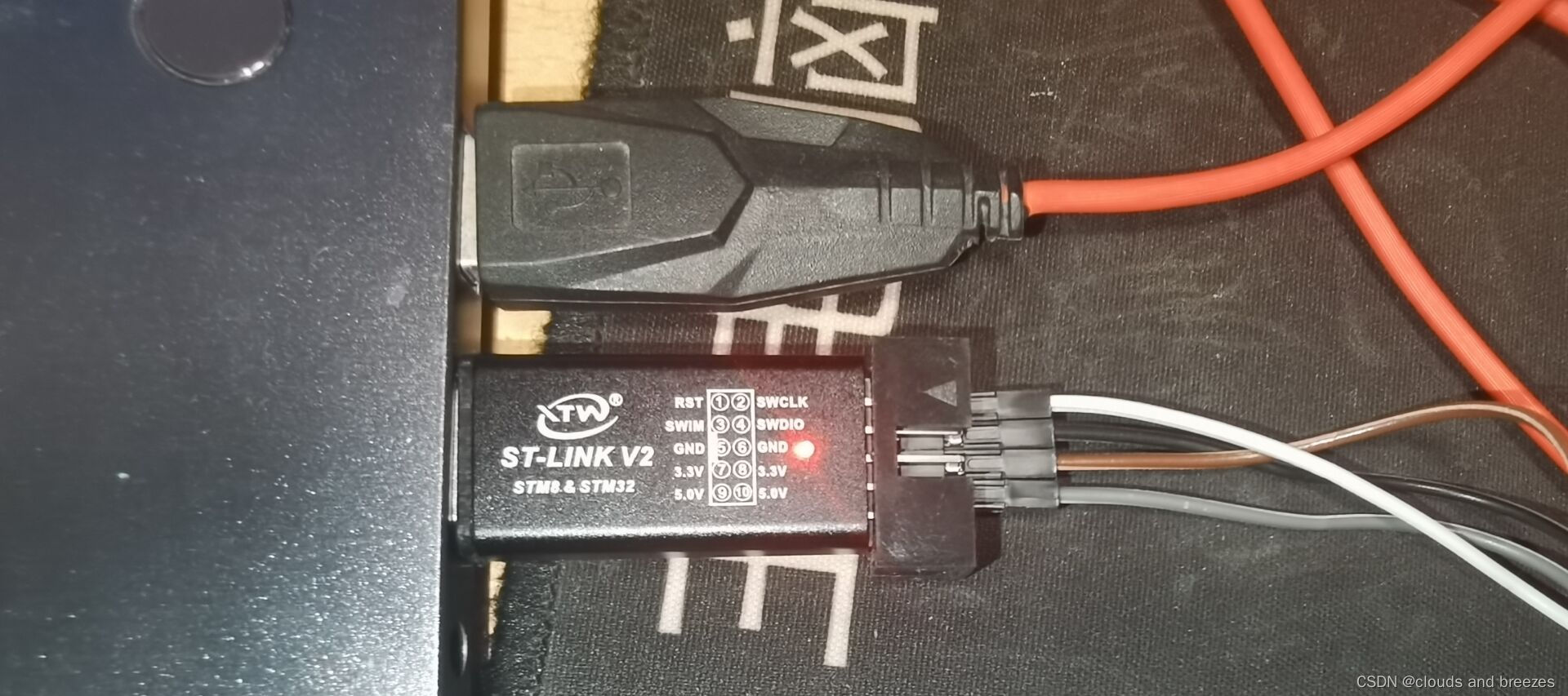
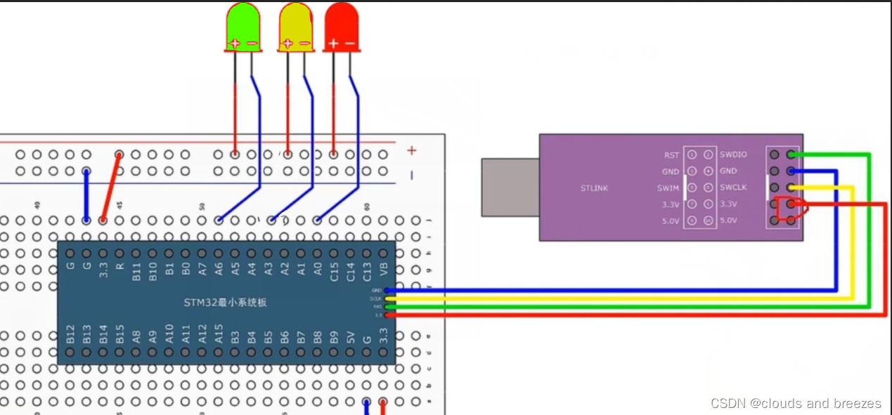
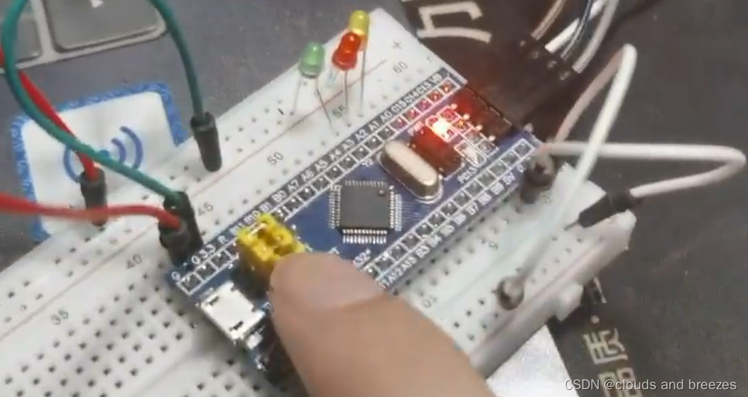
3.2 电路连接
硬件线路连接图如图所示
实物图如下:
3.3 编译烧录
3.4 实验效果

四、总结
通过本次实验学会了如何用代码在STM32上实现流水灯的操作,加强了自己的动手能力。


 被折叠的 条评论
为什么被折叠?
被折叠的 条评论
为什么被折叠?
 到【灌水乐园】发言


