


基于STM32单片机的智能手环系统设计
摘要
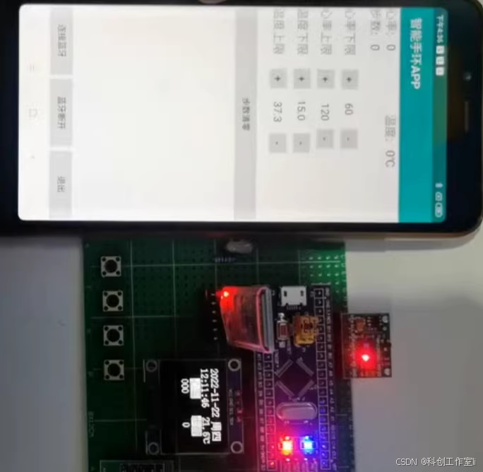
随着可穿戴设备的日益普及,智能手环已成为人们健康监测和日常活动追踪的重要工具。本文旨在设计一款基于STM32单片机的智能手环系统,通过集成多种传感器和无线通信模块,实现心率监测、体温检测、计步、时间显示及跌倒报警等功能。系统选用STM32F103C8T6单片机作为主控制器,结合MAX30102心率血氧传感器、DS18B20温度传感器、HC-05蓝牙模块、OLED显示器等硬件组件,构建了一个功能全面、性能稳定的智能手环系统。该系统能够实时监测用户的生理参数,并通过手机APP接收和查看数据,为用户提供便捷、全面的健康和运动监测服务。
关键词
STM32单片机;智能手环;心率监测;体温检测;计步器;蓝牙通信
Abstract
With the increasing popularity of wearable devices, smart bracelets have become important tools for people to monitor their health and track daily activities. This paper aims to design a smart bracelet system based on the STM32 microcontroller. By integrating various sensors and wireless communication modules, the system realizes functions such as heart rate monitoring, temperature detection, pedometer, time display, and fall alarm. The system selects the STM32F103C8T6 microcontroller as the main controller, combined with hardware components such as the MAX30102 heart rate and blood oxygen sensor, DS18B20 temperature sensor, HC-05 Bluetooth module, and OLED display, to build a smart bracelet system with comprehensive functions and stable performance. The system can monitor users' physiological parameters in real-time and receive and view data through a mobile app, providing users with convenient and comprehensive health and exercise monitoring services.
Keywords: STM32 microcontroller; smart bracelet; heart rate monitoring; temperature detection; pedometer; Bluetooth communication
一、引言
随着科技与时代的不断进步,智能穿戴设备逐渐成为人们日常生活中的重要组成部分。智能手环作为其中的代表产品,集合了多种健康监测和运动追踪功能,不仅提高了人们的健康意识,还在一定程度上保障了人们的生命安全。本文基于STM32单片机设计了一款功能全面的智能手环系统,旨在为用户提供便捷、准确的健康和运动监测服务。
二、系统方案设计
2.1 系统总体架构
本系统以STM32F103C8T6单片机为核心,结合心率血氧传感器MAX30102、温度传感器DS18B20、蓝牙模块HC-05、OLED显示器、实时时间芯片DS1302、计步器ADXL345及蜂鸣器报警模块等硬件组件,构建了智能手环系统的总体架构。系统能够实时监测用户的心率、体温、步数等生理参数,并通过蓝牙模块将手机APP与手环相连,实现数据的无线传输和查看。
2.2 主要功能模块
2.2.1 心率血氧监测模块
心率血氧监测模块采用MAX30102传感器,该传感器集成了红外和可见光LED以及光电探测器,能够同时检测心率和血氧饱和度。通过STM32单片机控制传感器采集数据,并进行处理和分析,最终将心率和血氧饱和度显示在OLED屏幕上,并可通过蓝牙模块传输至手机APP。
2.2.2 体温检测模块
体温检测模块采用DS18B20温度传感器,该传感器具有体积小、精度高、抗干扰能力强等优点。通过STM32单片机读取传感器的温度数据,并进行处理和分析,最终将体温显示在OLED屏幕上,并可通过蓝牙模块传输至手机APP。
2.2.3 计步器模块
计步器模块采用ADXL345加速度传感器,该传感器能够感知人体运动时的加速度变化,并通过算法计算出步数。通过STM32单片机读取传感器的加速度数据,并进行处理和分析,最终将步数显示在OLED屏幕上,同时可根据步数计算走路距离和平均速度。
2.2.4 时间显示模块
时间显示模块采用DS1302实时时间芯片,该芯片具有精度高、功耗低等优点。通过STM32单片机读取芯片的时间数据,并进行处理和分析,最终将当前时间显示在OLED屏幕上。
2.2.5 跌倒报警模块
跌倒报警模块通过ADXL345加速度传感器检测用户姿态变化,当检测到用户跌倒时,触发蜂鸣器报警,并通过蓝牙模块将当前数据和位置发送到手机端进行提醒。
2.2.6 蓝牙通信模块
蓝牙通信模块采用HC-05蓝牙模块,该模块具有传输距离远、稳定性好等优点。通过STM32单片机控制蓝牙模块实现与手机APP的无线通信,将手环采集的数据实时传输至手机端进行显示和提醒。
三、硬件设计
3.1 单片机选型及电路设计
本系统选用STM32F103C8T6单片机作为主控制器。STM32F103C8T6是一款超低功耗的32位混合型单片机,具有高可靠性、低功耗、易扩展、体积小、性价比高、电路简单等优势,非常适合用于智能手环等智能化产品中。单片机电路设计包括电源电路、复位电路、时钟电路等部分,确保单片机能够正常工作。
3.2 传感器选型及电路设计
3.2.1 心率血氧传感器电路设计
心率血氧传感器采用MAX30102模块,该模块通过I2C总线与STM32单片机进行通信。电路设计中需要考虑传感器的供电电压、信号采集电路以及I2C通信接口等部分,确保传感器能够准确采集心率和血氧数据。
3.2.2 温度传感器电路设计
温度传感器采用DS18B20模块,该模块通过单总线与STM32单片机进行通信。电路设计中需要考虑传感器的供电电压、信号采集电路以及单总线通信接口等部分,确保传感器能够准确采集温度数据。
3.2.3 加速度传感器电路设计
加速度传感器采用ADXL345模块,该模块通过I2C总线与STM32单片机进行通信。电路设计中需要考虑传感器的供电电压、信号采集电路以及I2C通信接口等部分,确保传感器能够准确采集加速度数据,并实现计步和跌倒报警等功能。
3.3 显示模块设计
显示模块采用OLED液晶显示屏,该显示屏具有显示清晰、功耗低等优点。通过STM32单片机控制显示屏实现数据的实时显示,包括心率、血氧、体温、步数、时间等数据。电路设计中需要考虑显示屏的供电电压、信号接口以及显示驱动电路等部分。
3.4 蓝牙通信模块设计
蓝牙通信模块采用HC-05模块,该模块通过串口与STM32单片机进行通信。电路设计中需要考虑模块的供电电压、串口通信接口以及天线部分等,确保蓝牙模块能够稳定实现与手机APP的无线通信。
3.5 电源模块设计
电源模块采用直流5V供电,包括一个3脚的电源座子和6脚的电源开关。电源座子用于连接外部的电源插头,电源开关用于控制整个单片机的电路开和关。电路设计中需要考虑电源的滤波和保护等部分,确保电源的稳定性和安全性。
四、软件设计
4.1 软件总体架构
本系统软件设计采用模块化思想,将各个功能模块进行拆分和独立设计。软件总体架构包括主程序、初始化程序、数据采集与处理程序、数据显示与传输程序等部分。主程序负责协调各个模块的工作,初始化程序负责系统的初始化配置,数据采集与处理程序负责采集和处理传感器的数据,数据显示与传输程序负责将数据显示在OLED屏幕上并通过蓝牙模块传输至手机APP。
4.2 数据采集与处理程序设计
数据采集与处理程序负责采集心率血氧传感器、温度传感器和加速度传感器的数据,并进行处理和分析。程序中需要设置传感器的采样频率和数据采集周期,确保数据的准确性和实时性。同时,需要对采集到的数据进行滤波和处理,以提高数据的稳定性和可靠性。
4.3 数据显示与传输程序设计
数据显示与传输程序负责将采集到的数据显示在OLED屏幕上,并通过蓝牙模块传输至手机APP。程序中需要设置显示屏的刷新频率和数据传输周期,确保数据的实时更新和传输。同时,需要对传输的数据进行格式化和加密处理,以提高数据的安全性和可靠性。
4.4 跌倒报警程序设计
跌倒报警程序通过加速度传感器检测用户姿态变化,当检测到用户跌倒时,触发蜂鸣器报警,并通过蓝牙模块将当前数据和位置发送到手机端进行提醒。程序中需要设置跌倒检测的阈值和报警条件,确保跌倒报警的准确性和及时性。
五、系统测试与优化
5.1 系统测试
在系统完成后,需要进行全面的测试以确保系统的稳定性和可靠性。测试内容包括各个功能模块的功能测试、性能测试以及整体系统的联调测试。通过测试可以发现系统中存在的问题和缺陷,并进行相应的优化和改进。
5.2 系统优化
针对测试中发现的问题和缺陷,需要进行相应的优化和改进。优化内容包括硬件电路的改进、软件程序的优化以及系统整体性能的提升。通过优化可以提高系统的稳定性和可靠性,提升用户体验。
六、结论与展望
本文基于STM32单片机设计了一款功能全面的智能手环系统,通过集成多种传感器和无线通信模块,实现了心率监测、体温检测、计步、时间显示及跌倒报警等功能。系统具有稳定性好、准确性高、功耗低等优点,能够为用户提供便捷、全面的健康和运动监测服务。未来,我们将继续优化系统的性能和功能,拓展更多的应用场景,为用户提供更加智能、便捷的健康管理方案。
参考文献
/**
******************************************************************************
* @file stm32f10x_gpio.c
* @author MCD Application Team
* @version V3.5.0
* @date 11-March-2011
* @brief This file provides all the GPIO firmware functions.
******************************************************************************
* @attention
*
* THE PRESENT FIRMWARE WHICH IS FOR GUIDANCE ONLY AIMS AT PROVIDING CUSTOMERS
* WITH CODING INFORMATION REGARDING THEIR PRODUCTS IN ORDER FOR THEM TO SAVE
* TIME. AS A RESULT, STMICROELECTRONICS SHALL NOT BE HELD LIABLE FOR ANY
* DIRECT, INDIRECT OR CONSEQUENTIAL DAMAGES WITH RESPECT TO ANY CLAIMS ARISING
* FROM THE CONTENT OF SUCH FIRMWARE AND/OR THE USE MADE BY CUSTOMERS OF THE
* CODING INFORMATION CONTAINED HEREIN IN CONNECTION WITH THEIR PRODUCTS.
*
* <h2><center>© COPYRIGHT 2011 STMicroelectronics</center></h2>
******************************************************************************
*/
/* Includes ------------------------------------------------------------------*/
#include "stm32f10x_gpio.h"
#include "stm32f10x_rcc.h"
/** @addtogroup STM32F10x_StdPeriph_Driver
* @{
*/
/** @defgroup GPIO
* @brief GPIO driver modules
* @{
*/
/** @defgroup GPIO_Private_TypesDefinitions
* @{
*/
/**
* @}
*/
/** @defgroup GPIO_Private_Defines
* @{
*/
/* ------------ RCC registers bit address in the alias region ----------------*/
#define AFIO_OFFSET (AFIO_BASE - PERIPH_BASE)
/* --- EVENTCR Register -----*/
/* Alias word address of EVOE bit */
#define EVCR_OFFSET (AFIO_OFFSET + 0x00)
#define EVOE_BitNumber ((uint8_t)0x07)
#define EVCR_EVOE_BB (PERIPH_BB_BASE + (EVCR_OFFSET * 32) + (EVOE_BitNumber * 4))
/* --- MAPR Register ---*/
/* Alias word address of MII_RMII_SEL bit */
#define MAPR_OFFSET (AFIO_OFFSET + 0x04)
#define MII_RMII_SEL_BitNumber ((u8)0x17)
#define MAPR_MII_RMII_SEL_BB (PERIPH_BB_BASE + (MAPR_OFFSET * 32) + (MII_RMII_SEL_BitNumber * 4))
#define EVCR_PORTPINCONFIG_MASK ((uint16_t)0xFF80)
#define LSB_MASK ((uint16_t)0xFFFF)
#define DBGAFR_POSITION_MASK ((uint32_t)0x000F0000)
#define DBGAFR_SWJCFG_MASK ((uint32_t)0xF0FFFFFF)
#define DBGAFR_LOCATION_MASK ((uint32_t)0x00200000)
#define DBGAFR_NUMBITS_MASK ((uint32_t)0x00100000)
/**
* @}
*/
/** @defgroup GPIO_Private_Macros
* @{
*/
/**
* @}
*/
/** @defgroup GPIO_Private_Variables
* @{
*/
/**
* @}
*/
/** @defgroup GPIO_Private_FunctionPrototypes
* @{
*/
/**
* @}
*/
/** @defgroup GPIO_Private_Functions
* @{
*/
/**
* @brief Deinitializes the GPIOx peripheral registers to their default reset values.
* @param GPIOx: where x can be (A..G) to select the GPIO peripheral.
* @retval None
*/
void GPIO_DeInit(GPIO_TypeDef* GPIOx)
{
/* Check the parameters */
assert_param(IS_GPIO_ALL_PERIPH(GPIOx));
if (GPIOx == GPIOA)
{
RCC_APB2PeriphResetCmd(RCC_APB2Periph_GPIOA, ENABLE);
RCC_APB2PeriphResetCmd(RCC_APB2Periph_GPIOA, DISABLE);
}
else if (GPIOx == GPIOB)
{
RCC_APB2PeriphResetCmd(RCC_APB2Periph_GPIOB, ENABLE);
RCC_APB2PeriphResetCmd(RCC_APB2Periph_GPIOB, DISABLE);
}
else if (GPIOx == GPIOC)
{
RCC_APB2PeriphResetCmd(RCC_APB2Periph_GPIOC, ENABLE);
RCC_APB2PeriphResetCmd(RCC_APB2Periph_GPIOC, DISABLE);
}
else if (GPIOx == GPIOD)
{
RCC_APB2PeriphResetCmd(RCC_APB2Periph_GPIOD, ENABLE);
RCC_APB2PeriphResetCmd(RCC_APB2Periph_GPIOD, DISABLE);
}
else if (GPIOx == GPIOE)
{
RCC_APB2PeriphResetCmd(RCC_APB2Periph_GPIOE, ENABLE);
RCC_APB2PeriphResetCmd(RCC_APB2Periph_GPIOE, DISABLE);
}
else if (GPIOx == GPIOF)
{
RCC_APB2PeriphResetCmd(RCC_APB2Periph_GPIOF, ENABLE);
RCC_APB2PeriphResetCmd(RCC_APB2Periph_GPIOF, DISABLE);
}
else
{
if (GPIOx == GPIOG)
{
RCC_APB2PeriphResetCmd(RCC_APB2Periph_GPIOG, ENABLE);
RCC_APB2PeriphResetCmd(RCC_APB2Periph_GPIOG, DISABLE);
}
}
}
/**
* @brief Deinitializes the Alternate Functions (remap, event control
* and EXTI configuration) registers to their default reset values.
* @param None
* @retval None
*/
void GPIO_AFIODeInit(void)
{
RCC_APB2PeriphResetCmd(RCC_APB2Periph_AFIO, ENABLE);
RCC_APB2PeriphResetCmd(RCC_APB2Periph_AFIO, DISABLE);
}
/**
* @brief Initializes the GPIOx peripheral according to the specified
* parameters in the GPIO_InitStruct.
* @param GPIOx: where x can be (A..G) to select the GPIO peripheral.
* @param GPIO_InitStruct: pointer to a GPIO_InitTypeDef structure that
* contains the configuration information for the specified GPIO peripheral.
* @retval None
*/
void GPIO_Init(GPIO_TypeDef* GPIOx, GPIO_InitTypeDef* GPIO_InitStruct)
{
uint32_t currentmode = 0x00, currentpin = 0x00, pinpos = 0x00, pos = 0x00;
uint32_t tmpreg = 0x00, pinmask = 0x00;
/* Check the parameters */
assert_param(IS_GPIO_ALL_PERIPH(GPIOx));
assert_param(IS_GPIO_MODE(GPIO_InitStruct->GPIO_Mode));
assert_param(IS_GPIO_PIN(GPIO_InitStruct->GPIO_Pin));
/*---------------------------- GPIO Mode Configuration -----------------------*/
currentmode = ((uint32_t)GPIO_InitStruct->GPIO_Mode) & ((uint32_t)0x0F);
if ((((uint32_t)GPIO_InitStruct->GPIO_Mode) & ((uint32_t)0x10)) != 0x00)
{
/* Check the parameters */
assert_param(IS_GPIO_SPEED(GPIO_InitStruct->GPIO_Speed));
/* Output mode */
currentmode |= (uint32_t)GPIO_InitStruct->GPIO_Speed;
}
/*---------------------------- GPIO CRL Configuration ------------------------*/
/* Configure the eight low port pins */
if (((uint32_t)GPIO_InitStruct->GPIO_Pin & ((uint32_t)0x00FF)) != 0x00)
{
tmpreg = GPIOx->CRL;
for (pinpos = 0x00; pinpos < 0x08; pinpos++)
{
pos = ((uint32_t)0x01) << pinpos;
/* Get the port pins position */
currentpin = (GPIO_InitStruct->GPIO_Pin) & pos;
if (currentpin == pos)
{
pos = pinpos << 2;
/* Clear the corresponding low control register bits */
pinmask = ((uint32_t)0x0F) << pos;
tmpreg &= ~pinmask;
/* Write the mode configuration in the corresponding bits */
tmpreg |= (currentmode << pos);
/* Reset the corresponding ODR bit */
if (GPIO_InitStruct->GPIO_Mode == GPIO_Mode_IPD)
{
GPIOx->BRR = (((uint32_t)0x01) << pinpos);
}
else
{
/* Set the corresponding ODR bit */
if (GPIO_InitStruct->GPIO_Mode == GPIO_Mode_IPU)
{
GPIOx->BSRR = (((uint32_t)0x01) << pinpos);
}
}
}
}
GPIOx->CRL = tmpreg;
}
/*---------------------------- GPIO CRH Configuration ------------------------*/
/* Configure the eight high port pins */
if (GPIO_InitStruct->GPIO_Pin > 0x00FF)
{
tmpreg = GPIOx->CRH;
for (pinpos = 0x00; pinpos < 0x08; pinpos++)
{
pos = (((uint32_t)0x01) << (pinpos + 0x08));
/* Get the port pins position */
currentpin = ((GPIO_InitStruct->GPIO_Pin) & pos);
if (currentpin == pos)
{
pos = pinpos << 2;
/* Clear the corresponding high control register bits */
pinmask = ((uint32_t)0x0F) << pos;
tmpreg &= ~pinmask;
/* Write the mode configuration in the corresponding bits */
tmpreg |= (currentmode << pos);
/* Reset the corresponding ODR bit */
if (GPIO_InitStruct->GPIO_Mode == GPIO_Mode_IPD)
{
GPIOx->BRR = (((uint32_t)0x01) << (pinpos + 0x08));
}
/* Set the corresponding ODR bit */
if (GPIO_InitStruct->GPIO_Mode == GPIO_Mode_IPU)
{
GPIOx->BSRR = (((uint32_t)0x01) << (pinpos + 0x08));
}
}
}
GPIOx->CRH = tmpreg;
}
}
/**
* @brief Fills each GPIO_InitStruct member with its default value.
* @param GPIO_InitStruct : pointer to a GPIO_InitTypeDef structure which will
* be initialized.
* @retval None
*/
void GPIO_StructInit(GPIO_InitTypeDef* GPIO_InitStruct)
{
/* Reset GPIO init structure parameters values */
GPIO_InitStruct->GPIO_Pin = GPIO_Pin_All;
GPIO_InitStruct->GPIO_Speed = GPIO_Speed_2MHz;
GPIO_InitStruct->GPIO_Mode = GPIO_Mode_IN_FLOATING;
}
/**
* @brief Reads the specified input port pin.
* @param GPIOx: where x can be (A..G) to select the GPIO peripheral.
* @param GPIO_Pin: specifies the port bit to read.
* This parameter can be GPIO_Pin_x where x can be (0..15).
* @retval The input port pin value.
*/
uint8_t GPIO_ReadInputDataBit(GPIO_TypeDef* GPIOx, uint16_t GPIO_Pin)
{
uint8_t bitstatus = 0x00;
/* Check the parameters */
assert_param(IS_GPIO_ALL_PERIPH(GPIOx));
assert_param(IS_GET_GPIO_PIN(GPIO_Pin));
if ((GPIOx->IDR & GPIO_Pin) != (uint32_t)Bit_RESET)
{
bitstatus = (uint8_t)Bit_SET;
}
else
{
bitstatus = (uint8_t)Bit_RESET;
}
return bitstatus;
}
/**
* @brief Reads the specified GPIO input data port.
* @param GPIOx: where x can be (A..G) to select the GPIO peripheral.
* @retval GPIO input data port value.
*/
uint16_t GPIO_ReadInputData(GPIO_TypeDef* GPIOx)
{
/* Check the parameters */
assert_param(IS_GPIO_ALL_PERIPH(GPIOx));
return ((uint16_t)GPIOx->IDR);
}
/**
* @brief Reads the specified output data port bit.
* @param GPIOx: where x can be (A..G) to select the GPIO peripheral.
* @param GPIO_Pin: specifies the port bit to read.
* This parameter can be GPIO_Pin_x where x can be (0..15).
* @retval The output port pin value.
*/
uint8_t GPIO_ReadOutputDataBit(GPIO_TypeDef* GPIOx, uint16_t GPIO_Pin)
{
uint8_t bitstatus = 0x00;
/* Check the parameters */
assert_param(IS_GPIO_ALL_PERIPH(GPIOx));
assert_param(IS_GET_GPIO_PIN(GPIO_Pin));
if ((GPIOx->ODR & GPIO_Pin) != (uint32_t)Bit_RESET)
{
bitstatus = (uint8_t)Bit_SET;
}
else
{
bitstatus = (uint8_t)Bit_RESET;
}
return bitstatus;
}
/**
* @brief Reads the specified GPIO output data port.
* @param GPIOx: where x can be (A..G) to select the GPIO peripheral.
* @retval GPIO output data port value.
*/
uint16_t GPIO_ReadOutputData(GPIO_TypeDef* GPIOx)
{
/* Check the parameters */
assert_param(IS_GPIO_ALL_PERIPH(GPIOx));
return ((uint16_t)GPIOx->ODR);
}
/**
* @brief Sets the selected data port bits.
* @param GPIOx: where x can be (A..G) to select the GPIO peripheral.
* @param GPIO_Pin: specifies the port bits to be written.
* This parameter can be any combination of GPIO_Pin_x where x can be (0..15).
* @retval None
*/
void GPIO_SetBits(GPIO_TypeDef* GPIOx, uint16_t GPIO_Pin)
{
/* Check the parameters */
assert_param(IS_GPIO_ALL_PERIPH(GPIOx));
assert_param(IS_GPIO_PIN(GPIO_Pin));
GPIOx->BSRR = GPIO_Pin;
}
/**
* @brief Clears the selected data port bits.
* @param GPIOx: where x can be (A..G) to select the GPIO peripheral.
* @param GPIO_Pin: specifies the port bits to be written.
* This parameter can be any combination of GPIO_Pin_x where x can be (0..15).
* @retval None
*/
void GPIO_ResetBits(GPIO_TypeDef* GPIOx, uint16_t GPIO_Pin)
{
/* Check the parameters */
assert_param(IS_GPIO_ALL_PERIPH(GPIOx));
assert_param(IS_GPIO_PIN(GPIO_Pin));
GPIOx->BRR = GPIO_Pin;
}
/**
* @brief Sets or clears the selected data port bit.
* @param GPIOx: where x can be (A..G) to select the GPIO peripheral.
* @param GPIO_Pin: specifies the port bit to be written.
* This parameter can be one of GPIO_Pin_x where x can be (0..15).
* @param BitVal: specifies the value to be written to the selected bit.
* This parameter can be one of the BitAction enum values:
* @arg Bit_RESET: to clear the port pin
* @arg Bit_SET: to set the port pin
* @retval None
*/
void GPIO_WriteBit(GPIO_TypeDef* GPIOx, uint16_t GPIO_Pin, BitAction BitVal)
{
/* Check the parameters */
assert_param(IS_GPIO_ALL_PERIPH(GPIOx));
assert_param(IS_GET_GPIO_PIN(GPIO_Pin));
assert_param(IS_GPIO_BIT_ACTION(BitVal));
if (BitVal != Bit_RESET)
{
GPIOx->BSRR = GPIO_Pin;
}
else
{
GPIOx->BRR = GPIO_Pin;
}
}
/**
* @brief Writes data to the specified GPIO data port.
* @param GPIOx: where x can be (A..G) to select the GPIO peripheral.
* @param PortVal: specifies the value to be written to the port output data register.
* @retval None
*/
void GPIO_Write(GPIO_TypeDef* GPIOx, uint16_t PortVal)
{
/* Check the parameters */
assert_param(IS_GPIO_ALL_PERIPH(GPIOx));
GPIOx->ODR = PortVal;
}
/**
* @brief Locks GPIO Pins configuration registers.
* @param GPIOx: where x can be (A..G) to select the GPIO peripheral.
* @param GPIO_Pin: specifies the port bit to be written.
* This parameter can be any combination of GPIO_Pin_x where x can be (0..15).
* @retval None
*/
void GPIO_PinLockConfig(GPIO_TypeDef* GPIOx, uint16_t GPIO_Pin)
{
uint32_t tmp = 0x00010000;
/* Check the parameters */
assert_param(IS_GPIO_ALL_PERIPH(GPIOx));
assert_param(IS_GPIO_PIN(GPIO_Pin));
tmp |= GPIO_Pin;
/* Set LCKK bit */
GPIOx->LCKR = tmp;
/* Reset LCKK bit */
GPIOx->LCKR = GPIO_Pin;
/* Set LCKK bit */
GPIOx->LCKR = tmp;
/* Read LCKK bit*/
tmp = GPIOx->LCKR;
/* Read LCKK bit*/
tmp = GPIOx->LCKR;
}
/**
* @brief Selects the GPIO pin used as Event output.
* @param GPIO_PortSource: selects the GPIO port to be used as source
* for Event output.
* This parameter can be GPIO_PortSourceGPIOx where x can be (A..E).
* @param GPIO_PinSource: specifies the pin for the Event output.
* This parameter can be GPIO_PinSourcex where x can be (0..15).
* @retval None
*/
void GPIO_EventOutputConfig(uint8_t GPIO_PortSource, uint8_t GPIO_PinSource)
{
uint32_t tmpreg = 0x00;
/* Check the parameters */
assert_param(IS_GPIO_EVENTOUT_PORT_SOURCE(GPIO_PortSource));
assert_param(IS_GPIO_PIN_SOURCE(GPIO_PinSource));
tmpreg = AFIO->EVCR;
/* Clear the PORT[6:4] and PIN[3:0] bits */
tmpreg &= EVCR_PORTPINCONFIG_MASK;
tmpreg |= (uint32_t)GPIO_PortSource << 0x04;
tmpreg |= GPIO_PinSource;
AFIO->EVCR = tmpreg;
}
/**
* @brief Enables or disables the Event Output.
* @param NewState: new state of the Event output.
* This parameter can be: ENABLE or DISABLE.
* @retval None
*/
void GPIO_EventOutputCmd(FunctionalState NewState)
{
/* Check the parameters */
assert_param(IS_FUNCTIONAL_STATE(NewState));
*(__IO uint32_t *) EVCR_EVOE_BB = (uint32_t)NewState;
}
/**
* @brief Changes the mapping of the specified pin.
* @param GPIO_Remap: selects the pin to remap.
* This parameter can be one of the following values:
* @arg GPIO_Remap_SPI1 : SPI1 Alternate Function mapping
* @arg GPIO_Remap_I2C1 : I2C1 Alternate Function mapping
* @arg GPIO_Remap_USART1 : USART1 Alternate Function mapping
* @arg GPIO_Remap_USART2 : USART2 Alternate Function mapping
* @arg GPIO_PartialRemap_USART3 : USART3 Partial Alternate Function mapping
* @arg GPIO_FullRemap_USART3 : USART3 Full Alternate Function mapping
* @arg GPIO_PartialRemap_TIM1 : TIM1 Partial Alternate Function mapping
* @arg GPIO_FullRemap_TIM1 : TIM1 Full Alternate Function mapping
* @arg GPIO_PartialRemap1_TIM2 : TIM2 Partial1 Alternate Function mapping
* @arg GPIO_PartialRemap2_TIM2 : TIM2 Partial2 Alternate Function mapping
* @arg GPIO_FullRemap_TIM2 : TIM2 Full Alternate Function mapping
* @arg GPIO_PartialRemap_TIM3 : TIM3 Partial Alternate Function mapping
* @arg GPIO_FullRemap_TIM3 : TIM3 Full Alternate Function mapping
* @arg GPIO_Remap_TIM4 : TIM4 Alternate Function mapping
* @arg GPIO_Remap1_CAN1 : CAN1 Alternate Function mapping
* @arg GPIO_Remap2_CAN1 : CAN1 Alternate Function mapping
* @arg GPIO_Remap_PD01 : PD01 Alternate Function mapping
* @arg GPIO_Remap_TIM5CH4_LSI : LSI connected to TIM5 Channel4 input capture for calibration
* @arg GPIO_Remap_ADC1_ETRGINJ : ADC1 External Trigger Injected Conversion remapping
* @arg GPIO_Remap_ADC1_ETRGREG : ADC1 External Trigger Regular Conversion remapping
* @arg GPIO_Remap_ADC2_ETRGINJ : ADC2 External Trigger Injected Conversion remapping
* @arg GPIO_Remap_ADC2_ETRGREG : ADC2 External Trigger Regular Conversion remapping
* @arg GPIO_Remap_ETH : Ethernet remapping (only for Connectivity line devices)
* @arg GPIO_Remap_CAN2 : CAN2 remapping (only for Connectivity line devices)
* @arg GPIO_Remap_SWJ_NoJTRST : Full SWJ Enabled (JTAG-DP + SW-DP) but without JTRST
* @arg GPIO_Remap_SWJ_JTAGDisable : JTAG-DP Disabled and SW-DP Enabled
* @arg GPIO_Remap_SWJ_Disable : Full SWJ Disabled (JTAG-DP + SW-DP)
* @arg GPIO_Remap_SPI3 : SPI3/I2S3 Alternate Function mapping (only for Connectivity line devices)
* When the SPI3/I2S3 is remapped using this function, the SWJ is configured
* to Full SWJ Enabled (JTAG-DP + SW-DP) but without JTRST.
* @arg GPIO_Remap_TIM2ITR1_PTP_SOF : Ethernet PTP output or USB OTG SOF (Start of Frame) connected
* to TIM2 Internal Trigger 1 for calibration (only for Connectivity line devices)
* If the GPIO_Remap_TIM2ITR1_PTP_SOF is enabled the TIM2 ITR1 is connected to
* Ethernet PTP output. When Reset TIM2 ITR1 is connected to USB OTG SOF output.
* @arg GPIO_Remap_PTP_PPS : Ethernet MAC PPS_PTS output on PB05 (only for Connectivity line devices)
* @arg GPIO_Remap_TIM15 : TIM15 Alternate Function mapping (only for Value line devices)
* @arg GPIO_Remap_TIM16 : TIM16 Alternate Function mapping (only for Value line devices)
* @arg GPIO_Remap_TIM17 : TIM17 Alternate Function mapping (only for Value line devices)
* @arg GPIO_Remap_CEC : CEC Alternate Function mapping (only for Value line devices)
* @arg GPIO_Remap_TIM1_DMA : TIM1 DMA requests mapping (only for Value line devices)
* @arg GPIO_Remap_TIM9 : TIM9 Alternate Function mapping (only for XL-density devices)
* @arg GPIO_Remap_TIM10 : TIM10 Alternate Function mapping (only for XL-density devices)
* @arg GPIO_Remap_TIM11 : TIM11 Alternate Function mapping (only for XL-density devices)
* @arg GPIO_Remap_TIM13 : TIM13 Alternate Function mapping (only for High density Value line and XL-density devices)
* @arg GPIO_Remap_TIM14 : TIM14 Alternate Function mapping (only for High density Value line and XL-density devices)
* @arg GPIO_Remap_FSMC_NADV : FSMC_NADV Alternate Function mapping (only for High density Value line and XL-density devices)
* @arg GPIO_Remap_TIM67_DAC_DMA : TIM6/TIM7 and DAC DMA requests remapping (only for High density Value line devices)
* @arg GPIO_Remap_TIM12 : TIM12 Alternate Function mapping (only for High density Value line devices)
* @arg GPIO_Remap_MISC : Miscellaneous Remap (DMA2 Channel5 Position and DAC Trigger remapping,
* only for High density Value line devices)
* @param NewState: new state of the port pin remapping.
* This parameter can be: ENABLE or DISABLE.
* @retval None
*/
void GPIO_PinRemapConfig(uint32_t GPIO_Remap, FunctionalState NewState)
{
uint32_t tmp = 0x00, tmp1 = 0x00, tmpreg = 0x00, tmpmask = 0x00;
/* Check the parameters */
assert_param(IS_GPIO_REMAP(GPIO_Remap));
assert_param(IS_FUNCTIONAL_STATE(NewState));
if((GPIO_Remap & 0x80000000) == 0x80000000)
{
tmpreg = AFIO->MAPR2;
}
else
{
tmpreg = AFIO->MAPR;
}
tmpmask = (GPIO_Remap & DBGAFR_POSITION_MASK) >> 0x10;
tmp = GPIO_Remap & LSB_MASK;
if ((GPIO_Remap & (DBGAFR_LOCATION_MASK | DBGAFR_NUMBITS_MASK)) == (DBGAFR_LOCATION_MASK | DBGAFR_NUMBITS_MASK))
{
tmpreg &= DBGAFR_SWJCFG_MASK;
AFIO->MAPR &= DBGAFR_SWJCFG_MASK;
}
else if ((GPIO_Remap & DBGAFR_NUMBITS_MASK) == DBGAFR_NUMBITS_MASK)
{
tmp1 = ((uint32_t)0x03) << tmpmask;
tmpreg &= ~tmp1;
tmpreg |= ~DBGAFR_SWJCFG_MASK;
}
else
{
tmpreg &= ~(tmp << ((GPIO_Remap >> 0x15)*0x10));
tmpreg |= ~DBGAFR_SWJCFG_MASK;
}
if (NewState != DISABLE)
{
tmpreg |= (tmp << ((GPIO_Remap >> 0x15)*0x10));
}
if((GPIO_Remap & 0x80000000) == 0x80000000)
{
AFIO->MAPR2 = tmpreg;
}
else
{
AFIO->MAPR = tmpreg;
}
}
/**
* @brief Selects the GPIO pin used as EXTI Line.
* @param GPIO_PortSource: selects the GPIO port to be used as source for EXTI lines.
* This parameter can be GPIO_PortSourceGPIOx where x can be (A..G).
* @param GPIO_PinSource: specifies the EXTI line to be configured.
* This parameter can be GPIO_PinSourcex where x can be (0..15).
* @retval None
*/
void GPIO_EXTILineConfig(uint8_t GPIO_PortSource, uint8_t GPIO_PinSource)
{
uint32_t tmp = 0x00;
/* Check the parameters */
assert_param(IS_GPIO_EXTI_PORT_SOURCE(GPIO_PortSource));
assert_param(IS_GPIO_PIN_SOURCE(GPIO_PinSource));
tmp = ((uint32_t)0x0F) << (0x04 * (GPIO_PinSource & (uint8_t)0x03));
AFIO->EXTICR[GPIO_PinSource >> 0x02] &= ~tmp;
AFIO->EXTICR[GPIO_PinSource >> 0x02] |= (((uint32_t)GPIO_PortSource) << (0x04 * (GPIO_PinSource & (uint8_t)0x03)));
}
/**
* @brief Selects the Ethernet media interface.
* @note This function applies only to STM32 Connectivity line devices.
* @param GPIO_ETH_MediaInterface: specifies the Media Interface mode.
* This parameter can be one of the following values:
* @arg GPIO_ETH_MediaInterface_MII: MII mode
* @arg GPIO_ETH_MediaInterface_RMII: RMII mode
* @retval None
*/
void GPIO_ETH_MediaInterfaceConfig(uint32_t GPIO_ETH_MediaInterface)
{
assert_param(IS_GPIO_ETH_MEDIA_INTERFACE(GPIO_ETH_MediaInterface));
/* Configure MII_RMII selection bit */
*(__IO uint32_t *) MAPR_MII_RMII_SEL_BB = GPIO_ETH_MediaInterface;
}
/**
* @}
*/
/**
* @}
*/
/**
* @}
*/
/******************* (C) COPYRIGHT 2011 STMicroelectronics *****END OF FILE****/


 被折叠的 条评论
为什么被折叠?
被折叠的 条评论
为什么被折叠?
 到【灌水乐园】发言


