


目录
题目
需求(所要实现的功能):
(1)R1与R5 MPLS VPN
(2)R6与R7 MPLS VPN
(3)R7可以访问R2/3/4
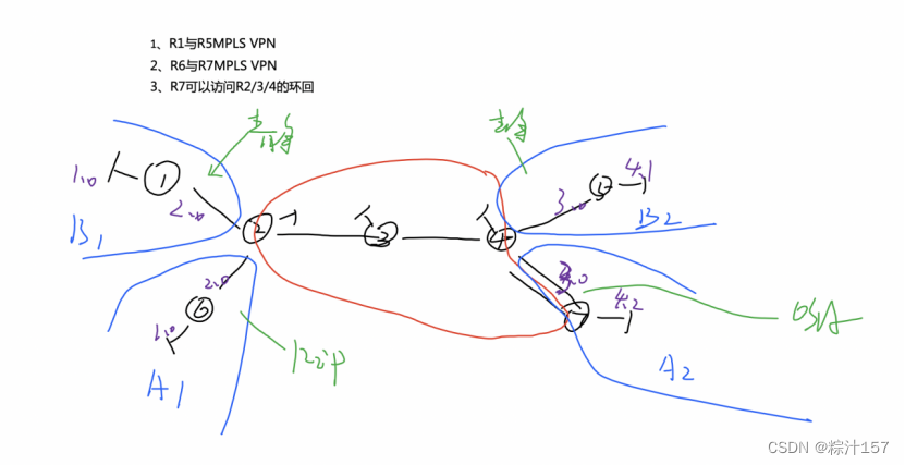
网络部署思路:
1、拓扑设计 -- IP地址规划

【2】配置
「1」底层--所有节点拥有合法ip地址
AR1
AR2 先不要配置g0/0/1和g0/0/2的接口IP地址
AR3
AR4 先不要配置g0/0/1和g4/0/0的接口IP地址
AR5
AR6
AR7


配置MPLS VPN
配置AR2的 g0/0/1和g0/0/2的接口IP地址 AR4的g0/0/1和g4/0/0的接口IP地址
[r2]ip vpn-instance b1
[r2-vpn-instance-b1]ipv4-family
[r2-vpn-instance-b1-af-ipv4]route-distinguisher 1:1
[r2-vpn-instance-b1-af-ipv4]vpn-target 1:1
IVT Assignment result:
Info: VPN-Target assignment is successful.
EVT Assignment result:
Info: VPN-Target assignment is successful.
[r2-vpn-instance-b1-af-ipv4]int g0/0/1
[r2-GigabitEthernet0/0/1]ip binding vpn-instance b1
Info: All IPv4 related configurations on this interface are removed!
Info: All IPv6 related configurations on this interface are removed!
[r2-GigabitEthernet0/0/1]ip add 172.168.2.2 24[r2]ip vpn-instance a1
[r2-vpn-instance-a1]ipv4-family
[r2-vpn-instance-a1-af-ipv4]route-distinguisher 2:2
[r2-vpn-instance-a1-af-ipv4]vpn-target 2:2
IVT Assignment result:
Info: VPN-Target assignment is successful.
EVT Assignment result:
Info: VPN-Target assignment is successful.
[r2-vpn-instance-a1-af-ipv4]int g0/0/2
[r2-GigabitEthernet0/0/2]ip binding vpn-instance a1
Info: All IPv4 related configurations on this interface are removed!
Info: All IPv6 related configurations on this interface are removed!
[r2-GigabitEthernet0/0/2]ip add 192.168.2.4 24
同理 AR4的g0/0/1和g4/0/0的接口IP地址
查看IP可达

「2」路由
AR2/3/4/7的公网IP地址实现IP可达
AR2
[r2]ospf 1 router-id 2.2.2.2
[r2-ospf-1]area 0
[r2-ospf-1-area-0.0.0.0]network 2.2.2.2 0.0.0.0
[r2-ospf-1-area-0.0.0.0]network 23.1.1.1 0.0.0.0AR3
[r3]ospf 1 router-id 3.3.3.3
[r3-ospf-1]area 0
[r3-ospf-1-area-0.0.0.0]network 3.3.3.3 0.0.0.0
[r3-ospf-1-area-0.0.0.0]network 23.1.1.2 0.0.0.0AR4
[r4]ospf 1 router-id 4.4.4.4
[r4-ospf-1]area 0
[r4-ospf-1-area-0.0.0.0]network 4.4.4.4 0.0.0.0
[r4-ospf-1-area-0.0.0.0]network 34.1.1.2 0.0.0.0AR7
[r7]ospf 1 router-id 7.7.7.7
[r7-ospf-1]area 0
[r7-ospf-1-area-0.0.0.0]network 47.1.1.2 0.0.0.0
「3」策略 -- 优化 安全 规则
- MPLS VPN
- CE将私有路由传递到PE端
- PE端在收到不同CE发送过来的相同网段路由时,使用RD值进行区分---格式X:X 32位
- PE端将附上RD的私有路由不能直接装载于本地公有路由表中,需要放置到对应的VRF(虚拟路由转发)空间内;之后再路由付RT值,用于传递到对端PE设备,对端区分信息;VPNV4路由=普通IPV4路由+RD+RT
- VPNV4路由需要MP-BGP来进行传递;对端基于RT值,将路由装载到对应的VRF空间内,再共享给对应的CE;
- 控制层面工作完成后,数据层面需要基于MPLS来工作,由于数据层面不能携带RD/RT值;故mpls将在数据包中压入两层标签,外层标签用于穿越中间设备,打破BGP路由黑洞;内层标签用于对应VRF空间;
(1)配置MPLS – LDP
AR2
[r2]mpls lsr-id 2.2.2.2
[r2]mpls
Info: Mpls starting, please wait... OK!
[r2-mpls]mpls ldp
[r2-mpls-ldp]int g0/0/0
[r2-GigabitEthernet0/0/0]mpls ldpAR3
[r3]mpls lsr-id 3.3.3.3
[r3]mpls
Info: Mpls starting, please wait... OK!
[r3-mpls]mpls ldp
[r3-mpls-ldp]int g0/0/0
[r3-GigabitEthernet0/0/0] mpls ldp
[r3-GigabitEthernet0/0/0]int g0/0/1
[r3-GigabitEthernet0/0/1]mpls
[r3-GigabitEthernet0/0/1] mpls ldpAR4
[r4]mpls lsr-id 4.4.4.4
[r4]mpls
Info: Mpls starting, please wait... OK!
[r4-mpls]mpls ldp
[r4-mpls-ldp]int g0/0/0
[r4-GigabitEthernet0/0/0]mpls
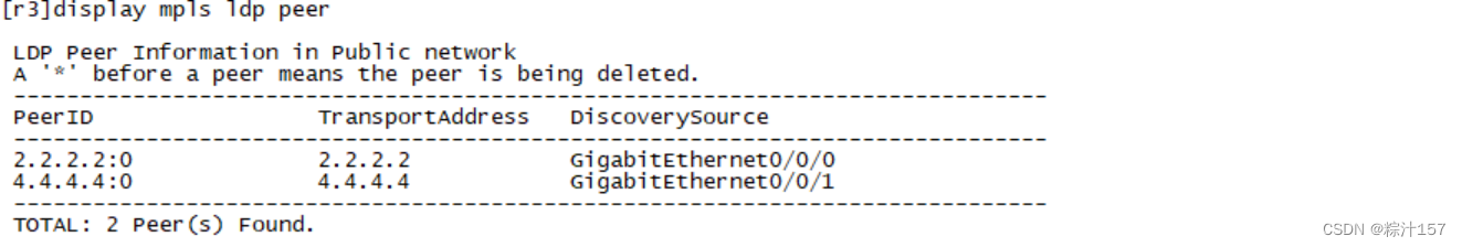
[r4-GigabitEthernet0/0/0] mpls ldp查看mpls ldp表
(2)PE与PE间建立MP-BPG邻居关系
AR2
[r2]bgp 2
[r2-bgp]router-id 2.2.2.2
[r2-bgp]peer 4.4.4.4 as-number 2
[r2-bgp]peer 4.4.4.4 connect-interface LoopBack 0
[r2-bgp]peer 4.4.4.4 next-hop-local
[r2-bgp]ipv4-family vpnv4
[r2-bgp-af-vpnv4]peer 4.4.4.4 enableAR4
[r4]bgp 2
[r4-bgp]router-id 4.4.4.4
[r4-bgp]peer 2.2.2.2 as-number 2
[r4-bgp]peer 2.2.2.2 connect-interface LoopBack 0
[r4-bgp]peer 2.2.2.2 next-hop-local
[r4-bgp]ipv4-family vpnv4同时还需要再在IPV4的家族模式中,与对端建立一个VPNV4的关系,用于传递VPNV4路由
[r4-bgp-af-vpnv4]peer 2.2.2.2 enable
(3)CE端与PE端交互路由
AR1/AR5为静态
CE端直接编写静态路由即可;
[r1]ip route-static 192.168.3.0 24 192.168.2.2
[r1]ip route-static 192.168.4.0 24 192.168.2.2[r5]ip route-static 192.168.1.0 24 192.168.3.2
[r5]ip route-static 192.168.2.0 24 192.168.3.2PE端编写到VRF空间内的静态路由
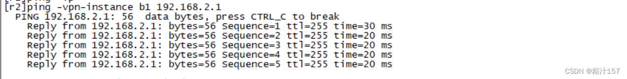
[r2]ip route-static vpn-instance b1 192.168.1.0 24 192.168.2.1
[r4]ip route-static vpn-instance b2 192.168.4.0 24 192.168.3.1
AR6为RIP,AR7为OSPF
CE端直接编写动态路由即可;
[r6]rip 1
[r6-rip-1]ver 2
[r6-rip-1]network 192.168.1.0
[r6-rip-1]network 192.168.2.0[r7]ospf 2 router-id 7.7.7.7
[r7-ospf-2]area 0
[r7-ospf-2-area-0.0.0.0]network 192.168.4.2 0.0.0.0
[r7-ospf-2-area-0.0.0.0]network 192.168.3.3 0.0.0.0PE端编写到VRF空间内的动态路由
[r2]rip 1 vpn-instance a1
[r2-rip-1]ver 2
[r2-rip-1]network 192.168.2.0[r4]ospf 2 vpn-instance a2
[r4-ospf-2]area 0
[r4-ospf-2-area-0.0.0.0]network 192.168.3.4 0.0.0.0
将本地vrf空间内的静态和直连路由重发布到BGP协议传递到对端的PE
之后使用双向重发布,实现路由共享
[r2]bgp 2
[r2-bgp]ipv4-family vpn-instance a1
[r2-bgp-a1]import-route rip 1[r2]bgp 2
[r2-bgp]ipv4-family vpn-instance b1
[r2-bgp-b1]import-route static
[r2-bgp-b1]import-route direct[r4]bgp 2
[r4-bgp]ipv4-family vpn-instance a2
[r4-bgp-a2]import-route ospf 2[r4]bgp 2
[r4-bgp]ipv4-family vpnv4
[r4-bgp]ipv4-family vpn-instance b2
[r4-bgp-b2]import-route static
[r4-bgp-b2]import-route direct
「4」测试
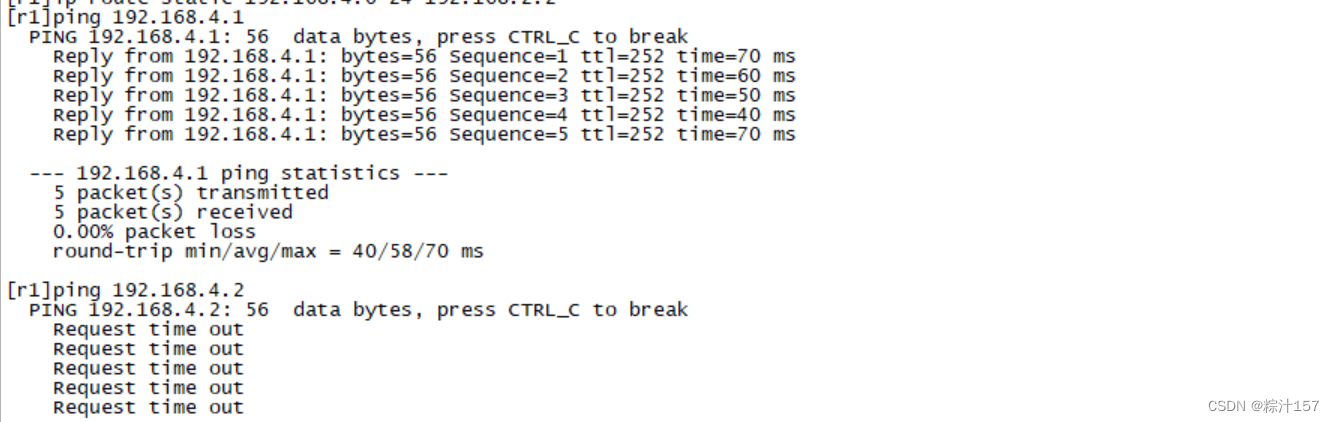
AR1去pingAR5和AR7
R7可以访问R2/3/4

「5」排错
【3】 维护
【4】升级


 782
782


 被折叠的 条评论
为什么被折叠?
被折叠的 条评论
为什么被折叠?
 到【灌水乐园】发言


