


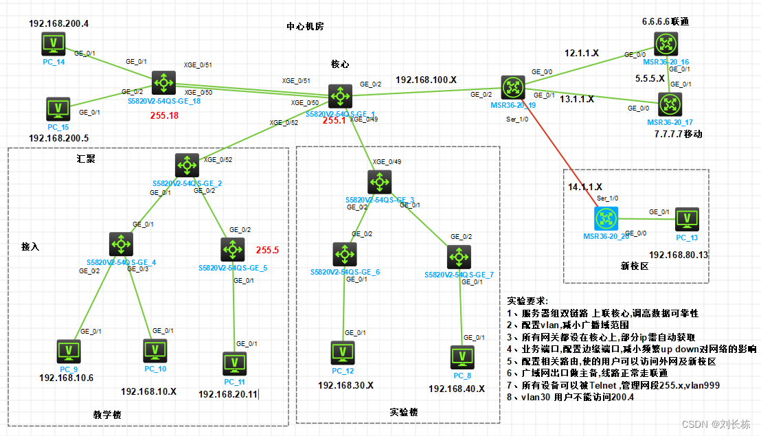
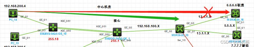
实验要求:
1、服务器组双链路 上联核心,调高数据可靠性
2、配置vlan,减小广播域范围
3、所有网关都设在核心上,部分ip需自动获取
4、业务端口,配置边缘端口,减小频繁up down对网络的影响
5、配置相关路由,使的用户可以访问外网及新校区
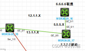
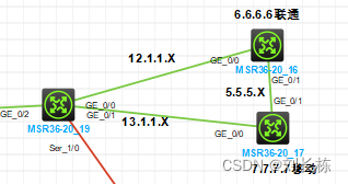
6、广域网出口做主备,线路正常走联通
7、所有设备可以被Telnet ,管理网段255.x,vlan999
8、vlan30 用户不能访问200.4
服务器sw网桥聚合
思路
1、起网桥聚合
2、聚合口为trunk
server-sw
[H3C]SY S-SW
[S-SW]vlan 200
[S-SW-vlan200]port g1/0/1
[S-SW-vlan200]port g1/0/2
dis
[S-SW-vlan200]int b 1
[S-SW-Bridge-Aggregation1]qu
[S-SW]int range Ten-GigabitEthernet1/0/50 to Ten-GigabitEthernet1/0/51
[S-SW-if-range]port link-aggregation group 1
[S-SW-if-range]qu

[S-SW]dis link-aggregation v
  Port             Status  Priority Oper-Key
--------------------------------------------------------------------------------
  XGE1/0/50        S       32768    1
  XGE1/0/51        S       32768    1
没有设置网桥模式为dynamic(动态)就会出现上面情况
[S-SW]int b 1
[S-SW-Bridge-Aggregation1]link mode dynamic ==开启动态模式==
[S-SW-Bridge-Aggregation1]dis link-aggregation v
System ID: 0x8000, 6e7e-6251-1200
Local:
Port Status Priority Oper-Key Flag
--------------------------------------------------------------------------------
XGE1/0/50 S 32768 1 {ACDEFG}
XGE1/0/51 U 32768 1 {ACG}
Remote:
Actor Partner Priority Oper-Key SystemID Flag
--------------------------------------------------------------------------------
XGE1/0/50 0 32768 0 0x8000, 0000-0000-0000 {DEF}
XGE1/0/51 0 32768 0 0x8000, 0000-0000-0000 {DEF}
====================由于对端摸开启 显示上面的 U ====================================
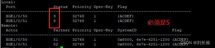
[S-SW-Bridge-Aggregation1]dis link-aggregation v
System ID: 0x8000, 6e7e-6251-1200
Local:
Port Status Priority Oper-Key Flag
--------------------------------------------------------------------------------
XGE1/0/50 S 32768 1 {ACDEF}
XGE1/0/51 S 32768 1 {ACDEF}
Remote:
Actor Partner Priority Oper-Key SystemID Flag
--------------------------------------------------------------------------------
XGE1/0/50 51 32768 1 0x8000, 6e7d-01a4-0100 {ACDEF}
XGE1/0/51 52 32768 1 0x8000, 6e7d-01a4-0100 {ACDEF}
在PC14(服务器)上ping网关 200.1 不通,分析原因为没有设置trunk
[S-SW-Bridge-Aggregation1]qu
[S-SW]in b 1
[S-SW-Bridge-Aggregation1]port link-ty trunk
		Configuring Ten-GigabitEthernet1/0/50 done.    ==这两done要出现==
		Configuring Ten-GigabitEthernet1/0/51 done.
[S-SW-Bridge-Aggregation1]por tr pe v a
		Configuring Ten-GigabitEthernet1/0/50 done.
		Configuring Ten-GigabitEthernet1/0/51 done.
核心sw
这个顺序好像很重要
sy SW1
vlan 200

int vlan 200
ip add 192.168.200.1 24

int b 1
qu

int range Ten-GigabitEthernet1/0/50 to Ten-GigabitEthernet1/0/51
port link-ag gr 1

int b 1
link mode dynamic
port link-ty trunk
port tr pe v all
验证
<H3C>PING 192.168.200.1
Ping 192.168.200.1 (192.168.200.1): 56 data bytes, press CTRL_C to break
56 bytes from 192.168.200.1: icmp_seq=0 ttl=255 time=0.000 ms
56 bytes from 192.168.200.1: icmp_seq=1 ttl=255 time=1.000 ms
56 bytes from 192.168.200.1: icmp_seq=2 ttl=255 time=1.000 m
2、配置vlan,减小广播域范围
思路
1、目标 vlan 10 vlan 20 vlan 30 vlan 40 vlan 80 vlan 200
疑问:服务器支路和pc9支路,如果按需开启vlan200 和999  会怎样 ?
答:就是要按需开启,没有必要开启其他的
2、用dis vlan b
vlan10段
核心sw1 起vlan trunk 虚接口
vlan 10
int vlan 10
ip ad 192.168.10.1 24
qu
iint Ten-GigabitEthernet1/0/52
port link-ty trunk
port trunk pe v all
检测 - vlan
[sw1]dis po tr
Interface             PVID    VLAN Passing
BAGG1                 1       1, 10, 200, 999
XGE1/0/50             1       1, 10, 200, 999
XGE1/0/51             1       1, 10, 200, 999
XGE1/0/52             1       1, 10, 200, 999
检测 -trunk
10        VLAN 0010                        BAGG1  XGE1/0/50  XGE1/0/51
                                           XGE1/0/52
200       VLAN 0200                        BAGG1  XGE1/0/50  XGE1/0/51
                                           XGE1/0/52
999       VLAN 0999                        BAGG1  XGE1/0/50  XGE1/0/51
                                           XGE1/0/52
检测 -虚接口
[sw1]dis ip in b
*down: administratively down
(s): spoofing  (l): loopback
Interface                Physical Protocol IP Address      Description
MGE0/0/0                 down     down     --              --
Vlan10                   up       up       192.168.10.1    --
Vlan200                  up       up       192.168.200.1   --
汇聚sw2 起vlan, 并三个trunk口
1、起vlan, 并三个trunk口 就ok
[sw-核心]sy sw-汇聚
[sw-汇聚]vlan 10
[sw-汇聚-vlan10]vlan 20
[sw-汇聚-vlan20]vlan 999
[sw-汇聚-vlan999]qu

[sw-汇聚]int Ten-GigabitEthernet1/0/52
[sw-汇聚-Ten-GigabitEthernet1/0/52]port link-ty trunk
[sw-汇聚-Ten-GigabitEthernet1/0/52]port tr pe v a
[sw-汇聚-GigabitEthernet1/0/1]qu

[sw-汇聚]int g1/0/1
[sw-汇聚-GigabitEthernet1/0/1]port link-ty trunk
[sw-汇聚-GigabitEthernet1/0/1]port tr pe v a
[sw-汇聚-GigabitEthernet1/0/1]int g1/0/2
[sw-汇聚-GigabitEthernet1/0/2]port link-ty trunk
[sw-汇聚-GigabitEthernet1/0/2]port tr pe v a
[sw2]dis vlan b
.......
10        VLAN 0010                        GE1/0/1  GE1/0/2  XGE1/0/52
20        VLAN 0020                        GE1/0/1  GE1/0/2  XGE1/0/52
999       VLAN 0999                        GE1/0/1  GE1/0/2  XGE1/0/52

[sw-汇聚]dis por tr
Interface             PVID    VLAN Passing
GE1/0/1               1       1, 10, 20, 999
GE1/0/2               1       1, 10, 20, 999
XGE1/0/52             1       1, 10, 20, 999
接入sw4 起vlan 开trunk
开通vlan10 (不用全部)并纳口 , 开通trunk 并all
[H3C]sy sw-接入
[sw-接入]vlan 10
[sw-接入-vlan10]port g1/0/2
[sw-接入-vlan10]port g1/0/3
[sw-接入-vlan10]int g1/0/1
[sw-接入-GigabitEthernet1/0/1]port link-ty tr
[sw-接入-GigabitEthernet1/0/1]port tr pe v a

========= 顺便业务端口
[sw4-vlan10]qu
[sw4]int range g1/0/2 to g1/0/3
[sw4-if-range]stp edged-port
10        VLAN 0010                        GE1/0/1  GE1/0/2  GE1/0/3
999       VLAN 0999                        GE1/0/1
pc9 能ping通网关10.1和200.1
<H3C>ping 192.168.10.1
Ping 192.168.10.1 (192.168.10.1): 56 data bytes, press CTRL_C to break
56 bytes from 192.168.10.1: icmp_seq=0 ttl=255 time=1.000 ms

<H3C>ping 192.168.200.1
Ping 192.168.200.1 (192.168.200.1): 56 data bytes, press CTRL_C to break
56 bytes from 192.168.200.1: icmp_seq=0 ttl=255 time=1.000 ms
56 bytes from 192.168.200.1: icmp_seq=1 ttl=255 time=1.000 ms
至此接入sw不能ping通 网关
[sw-接入]ping 192.168.10.1
Ping 192.168.10.1 (192.168.10.1): 56 data bytes, press CTRL_C to break
Request time out
Request time out
vlan 20段
sw1 起vlan 虚拟口
[sw1]vlan 20
[sw1-vlan20]int vlan 20
[sw1-Vlan-interface20]ip address 192.168.20.1 24
汇聚 sw 不用设置
sw5接入 起vlan 配trunk
[sw]sy sw5-接入
[sw5-接入]vlan 20
[sw5-接入-vlan20]por g1/0/1
[sw5-接入-vlan20]int g1/0/2
[sw5-接入-GigabitEthernet1/0/2]port link-ty tr
[sw5-接入-GigabitEthernet1/0/2]por tr pe v a
验证 ping 10.1 20.1 200.1都ok
<H3C>ping 192.168.200.1
Ping 192.168.200.1 (192.168.200.1): 56 data bytes, press CTRL_C to break
56 bytes from 192.168.200.1: icmp_seq=0 ttl=255 time=1.000 ms
vlan 30 40段
sw1起vlan 设虚拟口 配trunk
[sw1]vlan 30
[sw1-vlan30]int vlan 30
[sw1-Vlan-interface30]ip ad 192.168.30.1 24
[sw1-Vlan-interface30]vlan 40
[sw1-vlan40]int vlan 40
[sw1-Vlan-interface40]ip ad 192.168.40.1 24
[sw1-Vlan-interface40]qu

[sw1]int Ten-GigabitEthernet1/0/49
[sw1-Ten-GigabitEthernet1/0/49]port link-ty tr
[sw1-Ten-GigabitEthernet1/0/49]port link-ty trunk
[sw1-Ten-GigabitEthernet1/0/49]port tr pe v a
汇聚sw3 三个trunk
[sw-汇聚]int Ten-GigabitEthernet1/0/49
[sw-汇聚-Ten-GigabitEthernet1/0/49]port link-ty tr
[sw-汇聚-Ten-GigabitEthernet1/0/49]po tr pe v a
[sw-汇聚-Ten-GigabitEthernet1/0/49]qu

[sw-汇聚]int range g1/0/1 to g1/0/2
[sw-汇聚-if-range]port link-ty tr
[sw-汇聚-if-range]po tr pe v a
接入sw6 vlan30
[H3C]sy sw-接入
[sw-接入]vlan 30
[sw-接入-vlan30]por g1/0/1

[sw-接入-vlan30]int g1/0/2
[sw-接入-GigabitEthernet1/0/2]port link-ty tr
[sw-接入-GigabitEthernet1/0/2]po tr pe v a
验证vlan30
<H3C>ping 192.168.200.5
Ping 192.168.200.5 (192.168.200.5): 56 data bytes, press CTRL_C to break
56 bytes from 192.168.200.5: icmp_seq=0 ttl=254 time=2.000 ms
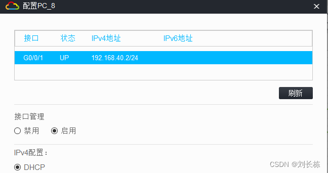
接入sw vlan40
[H3C]sy sw-接入
[sw-接入]vlan 40
[sw-接入-vlan40]port g1/0/1

[sw-接入-vlan4int g1/0/2
[sw-接入-GigabitEthernet1/0/2]port link-ty tr
[sw-接入-GigabitEthernet1/0/2]port tr pe v a
验证 vlan40 因未配置DHCP 不能 分配IP
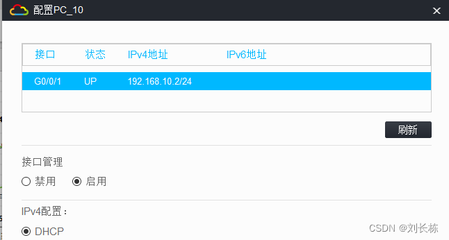
3、配置DHCP 使部分PC自动获取ip
核心 sw1 起dhcp 设地址段和网关
[sw1]dhcp enable
[sw1]dhcp server ip-pool 10
[sw1-dhcp-pool-10]network 192.168.10.0 mask 255.255.255.0
[sw1-dhcp-pool-10]gateway-list 192.168.10.1 24
[sw1-dhcp-pool-10]dns-list 8.8.8.8

[sw1]dhcp server ip-pool 40
[sw1-dhcp-pool-40]network 192.168.40.0 mask 255.255.255.0
[sw1-dhcp-pool-40]gateway-list 192.168.40.1
[sw1-dhcp-pool-40]dns-list 8.8.8.8
验证 等几分钟后
4 STP 协议树
核心为根网桥 优先级改成0
[sw1]stp priority 0
业务口配置边缘口
使得pc up down不影响网络
依次
[sw-接入]in g1/0/1
[sw-接入-GigabitEthernet1/0/1]stp edged-port
5、配置ospf 联通新校区
思路
1、核心sw1 起ospf ,宣告网段
[sw1]ospf 1
[sw1-ospf-1]area 1
[sw1-ospf-1-area-0.0.0.1]network 192.168.10.0 0.0.0.255
[sw1-ospf-1-area-0.0.0.1]network 192.168.20.0 0.0.0.255
[sw1-ospf-1-area-0.0.0.1]network 192.168.30.0 0.0.0.255
[sw1-ospf-1-area-0.0.0.1]network 192.168.40.0 0.0.0.255
[sw1-ospf-1-area-0.0.0.1]network 192.168.200.0 0.0.0.255
[sw1-ospf-1-area-0.0.0.1]network 192.168.100.0 0.0.0.255
2、外网R起ospf ,宣告网段
[R-外网]ospf 1
[R-外网-ospf-1]area 1
[R-外网-ospf-1-area-0.0.0.1]network 192.168.100.0 0.0.0.255
[R-外网-ospf-1-area-0.0.0.1]network 12.1.1.0 0.0.0.255
[R-外网-ospf-1-area-0.0.0.1]network 13.1.1.0 0.0.0.255
[R-外网-ospf-1-area-0.0.0.1]network 14.1.1.0 0.0.0.255
3、新校区 R 配IP 起ospf ,宣告网段
[R-新]int s1/0
[R-新-Serial1/0]ip address 14.1.1.2 24

[R-新-Serial1/0]int g0/0
[R-新-GigabitEthernet0/0]ip address 192.168.80.1 24

[R-新]ospf 1
[R-新-ospf-1-area-0.0.0.1]network 192.168.14.0 0.0.0.255  ======错误
[R-新-ospf-1-area-0.0.0.1]network 14.1.1.1  0.0.0.255
[R-新-ospf-1-area-0.0.0.1]dis this
#
 area 0.0.0.1
  network 14.1.1.0 0.0.0.255
  network 192.168.14.0 0.0.0.255
#
[R-新-ospf-1-area-0.0.0.1]un network 192.168.14.0 0.0.0.255
[R-新-ospf-1-area-0.0.0.1]dis this
#
 area 0.0.0.1
  network 14.1.1.0 0.0.0.255
#
return
[R-新-ospf-1-area-0.0.0.1]network 192.168.80.0 0.0.0.255
验证 用新校区路由器及PC_13可以ping通 服务器200.4
[R-新-Serial1/0]ping 192.168.200.4
Ping 192.168.200.4 (192.168.200.4): 56 data bytes, press CTRL+C to break
56 bytes from 192.168.200.4: icmp_seq=0 ttl=253 time=2.000 ms

[R-新-Serial1/0]ping 192.168.20.11
Ping 192.168.20.11 (192.168.20.11): 56 data bytes, press CTRL+C to break
56 bytes from 192.168.20.11: icmp_seq=0 ttl=253 time=1.000 ms
<H3C>ping 192.168.200.1
Ping 192.168.200.1 (192.168.200.1): 56 data bytes, press CTRL_C to break
56 bytes from 192.168.200.1: icmp_seq=0 ttl=253 time=1.000 ms
**PC_9pingPC_13
<H3C>ping 192.168.80.13
Ping 192.168.80.13 (192.168.80.13): 56 data bytes, press CTRL_C to break
56 bytes from 192.168.80.13: icmp_seq=0 ttl=252 time=2.000 ms
6、访问外网
1) 核心 sw1 改02口为route模式,并设置地址
[sw1]int g1/0/2
[sw1-GigabitEthernet1/0/2]port link-mode route
[sw1-GigabitEthernet1/0/2]ip address 192.168.100.1 24
2) R-外网 设各口IP地址
[R-外网]int g0/2
[R-外网-GigabitEthernet0/2]ip a 192.168.100.2 24

[R-外网-GigabitEthernet0/2]int g0/0
[R-外网-GigabitEthernet0/0]ip a 12.1.1.1 24
[R-外网-GigabitEthernet0/0]int g0/1
[R-外网-GigabitEthernet0/1]ip a 13.1.1.1 24

[R-外网-GigabitEthernet0/1]int s1/0
[R-外网-Serial1/0]ip ad 14.1.1.1 24
至此 PC_可以访问到12.1.1.1 但到不了 12.1.1.2 更到不了 6.6.6.6
<H3C>ping 192.168.80.13
Ping 192.168.80.13 (192.168.80.13): 56 data bytes, press CTRL_C to break
56 bytes from 192.168.80.13: icmp_seq=0 ttl=252 time=2.000 ms
56 bytes from 192.168.80.13: icmp_seq=0 ttl=252 time=2.000 ms

ping 12.1.1.1
Ping 12.1.1.1 (12.1.1.1): 56 data bytes, press CTRL_C to break
56 bytes from 12.1.1.1: icmp_seq=0 ttl=254 time=1.000 ms
56 bytes from 12.1.1.1: icmp_seq=0 ttl=254 time=1.000 ms

ping 12.1.1.2
Ping 12.1.1.2 (12.1.1.2): 56 data bytes, press CTRL_C to break
Request time out
Request time out

[H3C]PING 6.6.6.6
Ping 6.6.6.6 (6.6.6.6): 56 data bytes, press CTRL_C to break
Request time out
应该配置 直连路由了吧
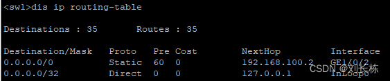
3) 核心sw1 设置默认路由,下一条100.2
[sw1]ip route-static 0.0.0.0 0 192.168.100.2
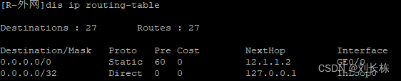
4) R-外网设置默认路由 ,吓一跳 12.1.1.2
[R-外网]ip route-static 0.0.0.0 0 12.1.1.2
5) R_联通 设置ip
[R-联通]int g0/0
[R-联通-GigabitEthernet0/0]ip address 12.1.1.2 24

[R-联通]int LoopBack 1
[R-联通-LoopBack1]ip address 6.6.6.6 24
至此连不通 6 6 6 6,应起acl
[H3C]PING 6.6.6.6
Ping 6.6.6.6 (6.6.6.6): 56 data bytes, press CTRL_C to break
Request time out
Request time out
6) R_外网 起acl NAT地址转换
[R-外网]acl basic 2000
[R-外网-acl-ipv4-basic-2000]rule permit source 192.168.0.0 0.0.255.255
# 规则:允许192.168.0.0段,通过无条件通过
[R-外网-acl-ipv4-basic-2000]int g0/0
[R-外网-GigabitEthernet0/0]nat outbound 2000
# 0/0端口 ,调用2000规则
7) 验证
验证 可以 ping 6.6.6.6
PING 6.6.6.6
Ping 6.6.6.6 (6.6.6.6): 56 data bytes, press CTRL_C to break
56 bytes from 6.6.6.6: icmp_seq=0 ttl=253 time=1.000 ms
56 bytes from 6.6.6.6: icmp_seq=1 ttl=253 time=2.000 ms
==R-外网
[R-外网]dis  ip in b
*down: administratively down
(s): spoofing  (l): loopback
Interface           Physical Protocol IP address/Mask    VPN instance Description
GE0/0               up       up       12.1.1.1/24        --           --
GE0/1               up       up       13.1.1.1/24        --           --
GE0/2               up       up       192.168.100.2/24   --           --
GE5/0               down     down     --                 --           --
GE5/1               down     down     --                 --           --
GE6/0               down     down     --                 --           --
GE6/1               down     down     --                 --           --
Ser1/0              up       up       14.1.1.1/24        --           --
Ser2/0              down     down     --                 --           --
Ser3/0              down     down     --                 --           --
Ser4/0              down     down     --                 --           -


[R-外网dis ip routing-table
Destinations : 27       Routes : 27
Destination/Mask   Proto   Pre Cost        NextHop         Interface
0.0.0.0/0          Static  60  0           12.1.1.2        GE0/0
0.0.0.0/32         Direct  0   0           127.0.0.1       InLoop0
12.1.1.0/24        Direct  0   0           12.1.1.1        GE0/0
12.1.1.1/32        Direct  0   0           127.0.0.1       InLoop0
12.1.1.255/32      Direct  0   0           12.1.1.1        GE0/0
13.1.1.0/24        Direct  0   0           13.1.1.1        GE0/1
13.1.1.1/32        Direct  0   0           127.0.0.1       InLoop0
13.1.1.255/32      Direct  0   0           13.1.1.1        GE0/1
14.1.1.0/24        Direct  0   0           14.1.1.1        Ser1/0
14.1.1.1/32        Direct  0   0           127.0.0.1       InLoop0
14.1.1.2/32        Direct  0   0           14.1.1.2        Ser1/0
14.1.1.255/32      Direct  0   0           14.1.1.1        Ser1/0
127.0.0.0/8        Direct  0   0           127.0.0.1       InLoop0
127.0.0.1/32       Direct  0   0           127.0.0.1       InLoop0
127.255.255.255/32 Direct  0   0           127.0.0.1       InLoop0
192.168.10.0/24    O_INTRA 10  2           192.168.100.1   GE0/2
192.168.20.0/24    O_INTRA 10  2           192.168.100.1   GE0/2
192.168.30.0/24    O_INTRA 10  2           192.168.100.1   GE0/2
192.168.40.0/24    O_INTRA 10  2           192.168.100.1   GE0/2
192.168.80.0/24    O_INTRA 10  1563        14.1.1.2        Ser1/0
192.168.100.0/24   Direct  0   0           192.168.100.2   GE0/2
192.168.100.2/32   Direct  0   0           127.0.0.1       InLoop0
192.168.100.255/32 Direct  0   0           192.168.100.2   GE0/2
192.168.200.0/24   O_INTRA 10  2           192.168.100.1   GE0/2
224.0.0.0/4        Direct  0   0           0.0.0.0         NULL0
224.0.0.0/24       Direct  0   0           0.0.0.0         NULL0
255.255.255.255/32 Direct  0   0           127.0.0.1       InLoop0
R-联通
<R-联通>dis ip in b
*down: administratively down
(s): spoofing  (l): loopback
Interface           Physical Protocol IP address/Mask    VPN instance Description
GE0/0               up       up       12.1.1.2/24        --           --
GE0/1               up       up       --                 --           --
GE0/2               down     down     --                 --           --
GE5/0               down     down     --                 --           --
GE5/1               down     down     --                 --           --
GE6/0               down     down     --                 --           --
GE6/1               down     down     --                 --           --
Loop1               up       up(s)    6.6.6.6/24         --           --
Ser1/0              down     down     --                 --           --
Ser2/0              down     down     --                 --           --
Ser3/0              down     down     --                 --           --
Ser4/0              down     down     --                 --           0


<R-联通>dis ip routing-table
Destinations : 13       Routes : 13
Destination/Mask   Proto   Pre Cost        NextHop         Interface
0.0.0.0/32         Direct  0   0           127.0.0.1       InLoop0
6.6.6.0/24         Direct  0   0           6.6.6.6         Loop1
6.6.6.6/32         Direct  0   0           127.0.0.1       InLoop0
6.6.6.255/32       Direct  0   0           6.6.6.6         Loop1
12.1.1.0/24        Direct  0   0           12.1.1.2        GE0/0
12.1.1.2/32        Direct  0   0           127.0.0.1       InLoop0
12.1.1.255/32      Direct  0   0           12.1.1.2        GE0/0
127.0.0.0/8        Direct  0   0           127.0.0.1       InLoop0
127.0.0.1/32       Direct  0   0           127.0.0.1       InLoop0
127.255.255.255/32 Direct  0   0           127.0.0.1       InLoop0
224.0.0.0/4        Direct  0   0           0.0.0.0         NULL0
224.0.0.0/24       Direct  0   0           0.0.0.0         NULL0
255.255.255.255/32 Direct  0   0           127.0.0.1       InLoop0
R_移动
<R_移动>dis ip in b
*down: administratively down
(s): spoofing  (l): loopback
Interface           Physical Protocol IP address/Mask    VPN instance Description
GE0/0               up       up       13.1.1.2/24        --           --
GE0/1               up       up       --                 --           --
GE0/2               down     down     --                 --           --
GE5/0               down     down     --                 --           --
GE5/1               down     down     --                 --           --
GE6/0               down     down     --                 --           --
GE6/1               down     down     --                 --           --
Loop3               up       up(s)    7.7.7.7/24         --           --
Ser1/0              down     down     --                 --           --
Ser2/0              down     down     --                 --           --
Ser3/0              down     down     --                 --           --
Ser4/0              down     down     --                 --           --
<R_移动>dis ip rou
<R_移动>dis ip routing-table

Destinations : 13       Routes : 13

Destination/Mask   Proto   Pre Cost        NextHop         Interface
0.0.0.0/32         Direct  0   0           127.0.0.1       InLoop0
7.7.7.0/24         Direct  0   0           7.7.7.7         Loop3
7.7.7.7/32         Direct  0   0           127.0.0.1       InLoop0
7.7.7.255/32       Direct  0   0           7.7.7.7         Loop3
13.1.1.0/24        Direct  0   0           13.1.1.2        GE0/0
13.1.1.2/32        Direct  0   0           127.0.0.1       InLoop0
13.1.1.255/32      Direct  0   0           13.1.1.2        GE0/0
127.0.0.0/8        Direct  0   0           127.0.0.1       InLoop0
127.0.0.1/32       Direct  0   0           127.0.0.1       InLoop0
127.255.255.255/32 Direct  0   0           127.0.0.1       InLoop0
224.0.0.0/4        Direct  0   0           0.0.0.0         NULL0
224.0.0.0/24       Direct  0   0           0.0.0.0         NULL0
255.255.255.255/32 Direct  0   0           127.0.0.1       InLoop0
7、外网双线备份 ,联通为主,移动为副 ,自动切换
1) R_外网 设路由 设优先级
ip route-static 0.0.0.0 0 13.1.1.2 preference 70
2) R_移动 设置ip
[R_移动]int LoopBack 3
[R_移动-LoopBack3]ip a 7.7.7.7 24

[R_移动-LoopBack3]int g0/0
[R_移动-GigabitEthernet0/0]ip a 13.1.1.2 24
检验
[R_移动]dis ip in b
*down: administratively down
(s): spoofing  (l): loopback
Interface           Physical Protocol IP address/Mask    VPN instance Description
GE0/0               up       up       13.1.1.2/24        --           --
GE0/1               up       up       --                 --           --
GE0/2               down     down     --                 --           --
GE5/0               down     down     --                 --           --
GE5/1               down     down     --                 --           --
GE6/0               down     down     --                 --           --
GE6/1               down     down     --                 --           --
Loop3               up       up(s)    7.7.7.7/24         --           --
3) 断开联通6.6.6.6 线路后,自动切换到 7.7.7.7
断开后 R_外网 路由表边长 注意第一行 优先级70
[R-外 dis ip routing-table
Destinations : 25       Routes : 25
Destination/Mask   Proto   Pre Cost        NextHop         Interface
0.0.0.0/0          Static  70  0           13.1.1.2        GE0/1
0.0.0.0/32         Direct  0   0           127.0.0.1       InLoop0
12.1.1.1/32        Direct  1   0           0.0.0.0         NULL0
13.1.1.0/24        Direct  0   0           13.1.1.1        GE0/1
13.1.1.1/32        Direct  0   0           127.0.0.1       InLoop0
13.1.1.255/32      Direct  0   0           13.1.1.1        GE0/1
14.1.1.0/24        Direct  0   0           14.1.1.1        Ser1/0
14.1.1.1/32        Direct  0   0           127.0.0.1       InLoop0
14.1.1.2/32        Direct  0   0           14.1.1.2        Ser1/0
14.1.1.255/32      Direct  0   0           14.1.1.1        Ser1/0
127.0.0.0/8        Direct  0   0           127.0.0.1       InLoop0
127.0.0.1/32       Direct  0   0           127.0.0.1       InLoop0
127.255.255.255/32 Direct  0   0           127.0.0.1       InLoop0
192.168.10.0/24    O_INTRA 10  2           192.168.100.1   GE0/2
192.168.20.0/24    O_INTRA 10  2           192.168.100.1   GE0/2
192.168.30.0/24    O_INTRA 10  2           192.168.100.1   GE0/2
192.168.40.0/24    O_INTRA 10  2           192.168.100.1   GE0/2
192.168.80.0/24    O_INTRA 10  1563        14.1.1.2        Ser1/0
192.168.100.0/24   Direct  0   0           192.168.100.2   GE0/2
192.168.100.2/32   Direct  0   0           127.0.0.1       InLoop0
192.168.100.255/32 Direct  0   0           192.168.100.2   GE0/2
192.168.200.0/24   O_INTRA 10  2           192.168.100.1   GE0/2
224.0.0.0/4        Direct  0   0           0.0.0.0         NULL0
224.0.0.0/24       Direct  0   0           0.0.0.0         NULL0
255.255.255.255/32 Direct  0   0           127.0.0.1       InLoop0
3.1)但是 ping不通 7.7.7.7 ,重新到R_外网NAT
ping不通 7.7.7.7 也不通 13.1.1.2 13.1.1.1通 ,说明没有配NAT
4) 返回 R_外网 匹配acl 规则
[R-外网]int g0/1
[R-外网-GigabitEthernet0/1]dis thi
# c发现 确实没有配置 NAT
interface GigabitEthernet0/1
 port link-mode route
 combo enable copper
 ip address 13.1.1.1 255.255.255.0

[R-外网-GigabitEthernet0/1]nat outbound 2000
# c再次检测

[R-外网-GigabitEthernet0/1]DIS THI
#
interface GigabitEthernet0/1
 port link-mode route
 combo enable copper
 ip address 13.1.1.1 255.255.255.0
 nat outbound 2000
# c返现有nat 规则
==用pc-14 ping7.7.7.7=
PING 7.7.7.7
Ping 7.7.7.7 (7.7.7.7): 56 data bytes, press CTRL_C to break
56 bytes from 7.7.7.7: icmp_seq=0 ttl=253 time=1.000 ms
56 bytes from 7.7.7.7: icmp_seq=1 ttl=253 time=1.000 ms
5) 再次接通 6.6.6.6 PC14 自动切换到 6.6.6.6
[H3C]PING 7.7.7.7
Ping 7.7.7.7 (7.7.7.7): 56 data bytes, press CTRL_C to break
56 bytes from 7.7.7.7: icmp_seq=0 ttl=253 time=2.000 ms
56 bytes from 7.7.7.7: icmp_seq=1 ttl=253 time=2.000 ms
Request time out
Request time out
Request time out
# c正连通的7在接通6.6后,断了
PING 6.6.6.6
Ping 6.6.6.6 (6.6.6.6): 56 data bytes, press CTRL_C to break
56 bytes from 6.6.6.6: icmp_seq=0 ttl=253 time=1.000 ms
56 bytes from 6.6.6.6: icmp_seq=1 ttl=253 time=1.000 ms
# c此时6.6 通路
[H3C]PING 7.7.7.7
Ping 7.7.7.7 (7.7.7.7): 56 data bytes, press CTRL_C to break
Request time out
Request time out
# c此时7.7 断路
8、所有设备科Telnet ,管理网段255.x,vlan999
1)所有设备可Telnet 每个设备都要配置 都一样
# c开启telnat服务
[sw1]telnet server enable
# c新增用户abc 设为管理员组,密码123  服务类型为Telnet
[sw1]local-user abc class mange
[sw1-luser-manage-abc]password simple 123
[sw1-luser-manage-abc]service-type telnet

# c改用户role 为网络管理员
[sw1-luser-manage-abc]authorization-attribute user-role network-admin

# c设用户登录方式为 账号密码  有意复制了 提示==
[sw1]use
[sw1]user-?
  user-group      Specify user group configuration information
  user-interface  Configure the line
  user-profile    Specify a user profile

[sw1]user-in
[sw1]user-interface ?
  INTEGER<0-147>  Number of the first line
  aux             AUX line
  class           Specify the line class to modify the default configuration
  console         Console line
  tty             Async serial line
  vty             Virtual type terminal (VTY) line

[sw1]user-interface vty ?
  INTEGER<0-63>  Number of the first line

[sw1]user-interface vty 0 4
[sw1-line-vty0-4]a
[sw1-line-vty0-4]authentication-mode ?
  none      Login without authentication
  password  Password authentication
  scheme    Authentication use AAA

[sw1-line-vty0-4]authentication-mode sc
[sw1-line-vty0-4]authentication-mode scheme
2) 通用代码 复制后 在每台设备上粘贴
telnet serv en
local-user abc class manage

pas sim 123
service-type telnet
authorization-attribute user-role network-admin
qu
user-interface vty 0 4
authentication-mode scheme
3)设置管理vlan 999和255.x的可以telnet
核心交换机和接入交换机以及路由器 , 要可被Telnet ,就必须有地址(虚接口),
故要设置管理vlan999.并给他一个255.x的地址
使得  所有pc都可以访问各交换机和路由器
① 核心sw 起管理vlan999 +ip
[sw1-luser-manage-abc]int vlan 999
[sw1-Vlan-interface999]ip address 192.168.255.1 24
②汇聚和接入交换机都要起管理vlan和管理地址
int vlan 999
ip add 192.168.255.x 24
③除主核心外 ,其他设备还要配置缺省路由 【不懂】
[sw14]ip route-static 0.0.0.0 0 192.168.255.1;用于管理流量的回包
总结以下,除了核心交换机,都应该这么设置
[sw-汇聚]vlan 999
[sw-汇聚-vlan999]int vlan 999
[sw-汇聚-Vlan-interface999]ip a 192.168.255.2 24
[sw-汇聚-Vlan-interface999]qu
[sw-汇聚]ip rou 0.0.0.0 0 192.168.255.1
# c默认路由的目的是为了管理流量回包,要不pc访问不了
检验排查
# c先看vlan999
[sw-接入]dis vlan
 Total VLANs: 3
 The VLANs include:
 1(default), 10, 999
# c2 排查 ip
[sw-接入]dis ip in b
*down: administratively down
(s): spoofing  (l): loopback
Interface                Physical Protocol IP Address      Description
MGE0/0/0                 down     down     --              --
Vlan999                  up       up       192.168.110.4   --
# c2 查看默认路由
[sw-接入]dis ip rou
Destinations : 13       Routes : 13
Destination/Mask   Proto   Pre Cost        NextHop         Interface
0.0.0.0/0          Static  60  0           192.168.255.1   Vlan999
9、vlan30 用户不能访问200.5 ACL NAT 是packet-filer
核心sw 设置高级阻断规则 acl
[sw1]acl advanced 3000
[sw1-acl-ipv4-adv-3000]rule deny ip source 192.168.30.0 0.0.0.255 destination 19
2.168.200.5 0.0.0.0
# 0.0.0.255? 是否合适
[sw1-acl-ipv4-adv-3000]qu
[sw1]int vlan 30
# 要设置  vlan
[sw1-Vlan-interface30]packet-filter 3000 inbound
# 不是nat  是packet-filer
检测
用192.168.30.12 ping 20.4 和200.5 成功
<H3C>ping 192.168.200.4
Ping 192.168.200.4 (192.168.200.4): 56 data bytes, press CTRL_C to break
56 bytes from 192.168.200.4: icmp_seq=0 ttl=254 time=2.000 ms
56 bytes from 192.168.200.4: icmp_seq=1 ttl=254 time=2.000 ms

ping 192.168.200.5
Ping 192.168.200.5 (192.168.200.5): 56 data bytes, press CTRL_C to break
Request time out
Request time out
用192.168.200.4 ping 30.12 通
ping 192.168.30.12
Ping 192.168.30.12 (192.168.30.12): 56 data bytes, press CTRL_C to break
56 bytes from 192.168.30.12: icmp_seq=0 ttl=254 time=1.000 ms
56 bytes from 192.168.30.12: icmp_seq=1 ttl=254 time=1.000 ms
用200.5 ping 30.12 不通
<H3C>ping 192.168.30.12
Ping 192.168.30.12 (192.168.30.12): 56 data bytes, press CTRL_C to break
Request time out
Request time out
结果很 ok 一切合乎设计要求
另 实验 如果 192.168.200.5 0.0.0.0.0 改成 0.0.0.255
[sw1-acl-ipv4-adv-3000]rule deny ip source 192.168.30.0 0.0.0.255 destination 19
2.168.200.5 0.0.0.0
[sw1-acl-ipv4-adv-3000]rule deny ip source 192.168.30.0 0.0.0.255 destination 19
2.168.200.5 0.0.0.255
#【结果】 0.0.0.255? 是否合适 255 就使得200段的所有ip都不能ping通
<H3C>ping 192.168.200.4
Ping 192.168.200.4 (192.168.200.4): 56 data bytes, press CTRL_C to break
Request time out
Request time out

ping 192.168.200.5
Ping 192.168.200.5 (192.168.200.5): 56 data bytes, press CTRL_C to break
Request time out
Request time out
查看sw1相关配置
[sw1]int vlan 30
[sw1-Vlan-interface30]dis thi
#
interface Vlan-interface30
 ip address 192.168.30.1 255.255.255.0
 packet-filter 3000 inbound
[sw1]acl advanced 3000
[sw1-acl-ipv4-adv-3000]dis th
#
acl advanced 3000
 rule 0 deny ip source 192.168.30.0 0.0.0.255 destination 192.168.200.0 0.0.0.255
再次改回来
[sw1]acl a 3000
[sw1-acl-ipv4-adv-3000]rule deny ip source 192.168.30.0 0.0.0.255 destination 19
2.168.200.5 0.0.0.0
[sw1-acl-ipv4-adv-3000]dis thi
#
acl advanced 3000
 rule 0 deny ip source 192.168.30.0 0.0.0.255 destination 192.168.200.5 0
30.12ping 200.5 互不通 ping’ 200.4 互通


 3701
3701


 被折叠的 条评论
为什么被折叠?
被折叠的 条评论
为什么被折叠?
 到【灌水乐园】发言


