


2.1.1 Ladder Logic
2.1.1梯形逻辑
Ladder logic is the main programming method used for PLCs. As mentioned before, ladder logic has been developed to mimic relay logic. The decision to use the relay logic diagrams was a strategic one. By selecting ladder logic as the main programming method, the amount of retraining needed for engineers and tradespeople was greatly reduced.
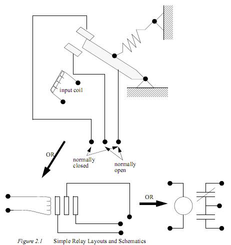
Modern control systems still include relays, but these are rarely used for logic. A relay is a simple device that uses a magnetic field to control a switch, as pictured in Figure 2.1. When a voltage is applied to the input coil, the resulting current creates a magnetic field. The magnetic field pulls a metal switch (or reed) towards it and the contacts touch, closing the switch. The contact that closes when the coil is energized is called normally open. The normally closed contacts touch when the input coil is not energized. Relays are normally drawn in schematic form using a circle to represent the input coil. The output contacts are shown with two parallel lines. Normally open contacts are shown as two lines, and will be open (non-conducting) when the input is not energized. Normally closed contacts are shown with two lines with a diagonal line through them. When the input coil is not energized the normally closed contacts will be closed (conducting).
梯形逻辑是PLC使用的主要编程方法。如前所述之前,梯形逻辑的发展是模仿继电器逻辑的。决定使用的继电器逻辑图是一个战略之一。通过选择梯形逻为主要辑编程方法,为培训所需的工程师和技工的资 金大大减少。
现代控制系统仍然包括继电器,但它们很少用在逻辑控制。继电器是一个简单的装置,它使用一个磁场来控制开关,如图图2.1 所示。当电压施加于输入线圈,产生的电流产生一个磁场。磁场拉动一个金属开关(或簧片),触电闭合,关闭开关。当线圈充电时触点闭合,称为常开触点。通闭触点当输入线圈不通电时闭合。在电路原理图中,继电器通常使用一个圆圈来表示输入线圈。输出触点以两条平行线表示。当输入线圈不通电时,常开触点显示为两条竖线,并会打开(不导电)。常闭触点显示为通过两条竖线的对角斜线。当输入线圈不通电通时,常闭触点将会闭合(导电)。
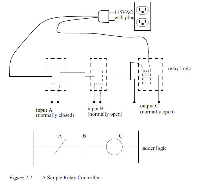
Relays are used to let one power source close a switch for another (often high current) power source, while keeping them isolated. An example of a relay in a simple control application is shown in Figure 2.2. In this system the first relay on the left is used as normally closed, and will allow current to flow until a voltage is applied to the input A. The second relay is normally open and will not allow current to flow until a voltage is applied to the input B. If current is flowing through the first two relays then current will flow through the coil in the third relay, and close the switch for output C. This circuit would normally be drawn in the ladder logic form. This can be read logically as C will be on if A
is off and B is on.
继电器用来让一个电源关闭另一个(通常高电流)电源,同时保持他们隔离。一个继电器控制程序简单的例子显示在图2.2。在这个系统中,左边第一个继电器使用常闭点,当电压加到输入点A时允许电流流过。第二个继电器是常开的,当电压加到输入B时,不允许电流流过。如果电流流过前两个继电器,那么电流将流过第三个继电器的线圈,并关闭输出C的开关。此电路通常被绘制成梯形逻辑形式。这可以被逻辑的解读为如果A off并且B on那么C on。
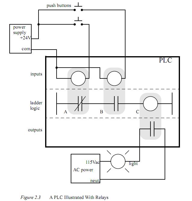
The example in Figure 2.2 does not show the entire control system, but only the logic. When we consider a PLC there are inputs, outputs, and the logic. Figure 2.3 shows a more complete representation of the PLC. Here there are two inputs from push buttons. We can imagine the inputs as activating 24V DC relay coils in the PLC. This in turn drives an output relay that switches 115V AC, that will turn on a light. Note, in actual PLCs inputs are never relays, but outputs are often relays. The ladder logic in the PLC is actually a computer program that the user can enter and change. Notice that both of the input push buttons are normally open, but the ladder logic inside the PLC has one normally open contact, and one normally closed contact. Do not think that the ladder logic in the PLC needs to match the inputs or outputs. Many beginners will get caught trying to make the ladder logic match the input types.
图2.2中的例子没有显示整个控制系统,只有逻辑。当我们考虑一个PLC应该有输入,输出和逻辑。图2.3显示了PLC更全面的表示。这里有两个输入形式的按钮。我们可以想像为输入是24V直流驱动PLC继电器线圈。这反过来驱动另一个输出继电器,开关115伏交流,这将打开一盏灯。请注意,在实际的PLC 系统中输入从来不用继电器,但输出常常是继电器。PLC梯形图逻辑其实是一种计算机程序,用户可以输入和变化。注意,两个输入的推按钮是常开,但在PLC梯形图逻辑有一个常开触点和一个常闭触点。不要认为在PLC梯形图逻辑需要匹配实际的输入或输出。许多初学者会试图使梯形图逻辑匹配实际的输入类型。
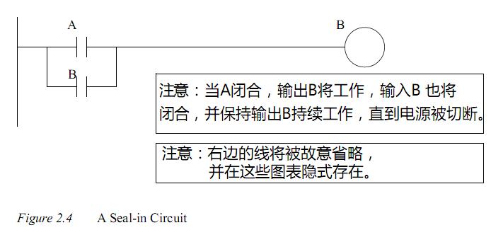
Many relays also have multiple outputs (throws) and this allows an output relay to also be an input simultaneously. The circuit shown in Figure 2.4 is an example of this, it is called a seal in circuit. In this circuit the current can flow through either branch of the circuit, through the contacts labelled A or B. The input B will only be on when the output B
is on. If B is off, and A is energized, then B will turn on. If B turns on then the input B will turn on, and keep output B on even if input A goes off. After B is turned on the output B will not turn off.
许多继电器也有多个输出(开关),这使一个输出继电器也可以同时输入。在图2.4所示的电路是一个例子,它是称为在保持电路。在此电路中的电流流过任一分支,通过标签为A的触点或B的触点。当输出端ON,输入端B将只能是ON。如果B是关闭的,而A通电,则B将打开。如果B打开,则输入B将打开,并且即使输入A关闭,输出B将保持ON。在ON后,输出B也不会关闭。


 1219
1219

 被折叠的 条评论
为什么被折叠?
被折叠的 条评论
为什么被折叠?
 到【灌水乐园】发言


