


VXLAN Primer-Part 1
http://www.borgcube.com/blogs/2011/11/vxlan-primer-part-1/
There has been a lot of chatter in the bloggersphere about the advent ofVirtual eXtensibleLocalAreaNetwork (VXLAN) and all the vendors that contributed to the standard as well as those that are planning on supporting the proposed IETF draft standard. In the next couple of articles I will attempt to describe how VXLAN is supposed to work as well as give you an idea of when you should consider implementing it, and how to implement it in your VMware Infrastructure (VI).
VXLAN Basics:
The basic use case for VXLAN is to connect two or more layer three (L3) networks and make them look like they share the same layer two (L2) domain. This would allow for virtual machines to live in two disparate networks yet still operate as if they were attached to the same L2. See section 3 of the VXLAN IETF draft as it addresses the networking problems that VXLAN is attempting to solve a lot better than I ever could.
To operate a VXLAN needs a couple of components in place:
-
Multicast support, IGMP and PIM
-
VXLAN Network Identifier (VNI)
-
VXLAN Gateway
-
VXLAN Tunnel End Point (VTEP)
-
VXLAN Segment/VXLAN Overlay Network
VXLAN is an L2 overlay over an L3 network. Each overlay network is known as a VXLAN Segment and identified by a unique 24-bit segment ID called a VXLAN Network Identifier (VNI). Only virtual machine on the same VNI are allowed to communicate with each other. Virtual machines are identified uniquely by the combination of their MAC addresses and VNI. As such it is possible to have duplicate MAC addresses in different VXLAN Segments without issue, but not in the same VXLAN Segments.

VXLAN Transport Header Format
Figure 1: VXLAN Packet Header
The original L2 packet that the virtual machines send out is encapsulated in a VXLAN header that includes the VNI associated with the VXLAN Segments that the virtual machine belongs to. The resulting packet is then wrapped in a UDP->IP->Ethernet packet for final delivery on the transport network. Due to this encapsulation you can think of VXLAN as a tunneling scheme with the ESX hosts making up the VXLAN Tunnel End Points (VTEP). The VTEPs are responsible for encapsulating the virtual machine traffic in a VXLAN header as well as stripping it off and presenting the destination virtual machine with the original L2 packet.
The encapsulation is comprised of the following modifications from standard UDP, IP and Ethernet frames:
Ethernet Header:
Destination Address – This is set to the MAC address of the destination VTEP if it is local of to that of the next hop device, usually a router, when the destination VTEP is on a different L3 network.
VLAN – This is optional in a VXLAN implementation and will be designated by an ethertype of 0×8100 and have an associated VLAN ID tag.
Ethertype – This is set to 0×0800 as the payload packet is an IPv4 packet. The initial VXLAN draft does not include an IPv6 implementation, but it is planned for the next draft.
IP Header:
Protocol – Set 0×11 to indicate that the frame contains a UDP packet
Source IP – IP address of originating VTEP
Destination IP – IP address of target VTEP. If this is not known, as in the case of a target virtual machine that the VTEP has not targeted before, a discovery process needs to be done by originating VTEP. This is done in a couple of steps:
-
Destination IP is replaced with the IP multicast group corresponding to the VNI of the originating virtual machine
-
All VTEPs that have subscribed to the IP multicast group receive the frame and decapsulate it learning the mapping of source virtual machine MAC address and host VTEP
-
The host VTEP of the destination virtual machine will then send the virtual machines response to the originating VTEP using its destination IP address as it learned this from the original multicast frame
-
The Source VTEP adds the new mapping of VTEP to virtual machine MAC address to its tables for future packets
-
UDP Header:
Source Port – Set by transmitting VTEP
VXLAN Port – IANA assigned VXLAN Port. This has not been assigned yet
UDP Checksum – This should be set to 0×0000. If the checksum is not set to 0×0000 by the source VTEP, then the receiving VTEP should verify the checksum and if not correct, the frame must be dropped and not decapsulated.
VXLAN Header:
VXLAN Flags – Reserved bits set to zero except bit 3, the I bit, which is set to 1 to for a valid VNI
VNI – 24-bit field that is the VXLAN Network Identifier
Reserved – A set of fields, 24 bits and 8 bits, that are reserved and set to zero
Putting it Together:

VXLAN: VM to VM communication
Figure 2: VM to VM communication
When VM1 wants to send a packet to VM2, it needs the MAC address of VM2 this is the process that is followed:
-
VM1 sends a ARP packet requesting the MAC address associated with 192.168.0.101
-
This ARP is encapsulated by VTEP1 into a multicast packet to the multicast group associated with VNI 864
-
All VTEPs see the multicast packet and add the association of VTEP1 and VM1 to its VXLAN tables
-
VTEP2 receives the multicast packet decapsulates it, and sends the original broadcast on portgroups associated with VNI 864
-
VM2 sees the ARP packet and responds with its MAC address
-
VTEP2 encapsulates the response as a unicast IP packet and sends it back to VTEP1 using IP routing
-
VTEP1 decapsulates the packet and passes it on to VM1
At this point VM1 knows the MAC address of VM2 and can send directed packets to it as shown in inFigure 2: VM to VM communication:
-
VM1 sends the IP packet to VM2 from IP address 192.168.0.100 to 192.168.0.101
-
VTEP1 takes the packet and encapsulates it by adding the following headers:
-
VXLAN header with VNI=864
-
Standard UDP header and sets the UDP checksum to 0×0000, and the destination port being the VXLAN IANA designated port. Cisco N1KV is currently using port ID 8472.
-
Standard IP header with the Destination being VTEP2’s IP address and Protocol 0×011 for the UDP packet used for delivery
-
Standard MAC header with the MAC address of the next hop. In this case it is the router Interface with MAC address 00:10:11:FE:D8:D2 which will use IP routing to send it to the destination
-
-
VTEP2 receives the packet as it has it’s MAC address as the destination. The packet is decapsulated and found to be a VXLAN packet due to the UDP destination port. At this point the VTEP will look up the associated portgroups for VNI 864 found in the VXLAN header. It will then verify that the target, VM2 in this case, is allowed to receive frames for VNI 864 due to it’s portgroup membership and pass the packet on if the verification passes.
-
VM2 receives the packet and deals with it like any other IP packet.
The return path for packet from VM2 to VM1 would follow the same IP route through the router on the way back.
VXLAN Primer-Part 2: Let’s Get Physical
http://www.borgcube.com/blogs/2012/03/vxlan-primer-part-2-lets-get-physical/
Now that the basics are in place with regards toVXLAN andMulticast, we can move on to what needs to be done to get your physical infrastructure ready for VXLAN. The promise of VXLAN is that you do not need to “upgrade” your physical network gear for VXLAN capable gear in order to be up and running, in reality there is very little you need to do. The basic things that need to be addressed are:
-
MTU increase
-
Multicast support
Let us cover this in a little more detail.
MTU Increase
Looking back to theVXLAN Primer-Part 1 we found that the encapsulation of an IPv4 packet will add an extra 50 bytes to the original frame. The recommendation is to increase the MTU to 1600 bytes. Why 1600 bytes when the VXLAN overhead is only 50 bytes? The reason for this is that the Guest could be doing VLAN tagging, on a max MTU packet of 1514 bytes, adding 4 bytes to the resulting packet. If the transport network requires that the VXLAN traffic be VLAN tagged, this will add another 4 bytes to the final packet. As such:
for IPv4:
1514(Guest) + 4(Guest VLAN tag) + 50(VXLAN) + 4(VXLAN Transport VLAN Tag) = 1572
for IPv6 (IPv6 headers add another 20 bytes):
1514(Guest) + 4(Guest VLAN) + 70(VXLAN IPv6) + 4(VXLAN Transport VLAN Tag) = 1592
IPv6 adds an extra 8 bytes of data and control packets bring this up to 1600 bytes.
The MTU change needs to be made at the vSwitch and on all physical gear that VXLAN traffic will traverse. On the physical gear, this will usually include the TOR switches, Core Switches and routers.
Caution should be taken if one is considering using VXLAN to transport virtual machine traffic that is already configured for jumbo frames and or jumbograms due to the resulting fragmentation.
Multicast Support
Multicast is required by VXLAN in order to transport virtual machine originated traffic such as unknown destination MAC packets, broadcasts, multicast or non IP traffic. It is also used for endpoint discovery by the VTEPs. For details on how multicast works have a look at the previous blog entry onmulticast.
There are a couple of ways to get started with multicasting for VXLAN use on the physical network, the simple way and the right way.
The Simple Way
For a simple one-datacenter configuration, you could take the simple route and put all your VTEPs on the same L2 network. This will allow you to run VXLAN without any changes to your network for multicast support. This is also an option to get you started as you prepare to do the right thing as detailed below.
You should be very aware in this configuration, that all multicast traffic will be treated like broadcast traffic by the physical switches. This traffic will be flooded to all ports in the L2 network they are in. This is not a terrible thing in a small VXLAN installation, or if the L2 is dedicated to the VTEPs, as it will get you up and running with no changes on the physical network.
The Right Way
The right way to prepare for VXLAN on the physical network is by enabling multicast support on the switches and routers.
-
On the layer 2 switches, you will need to enable IGMP snooping
-
On the routers you will need to setup an IGMP queryer
IGMP snooping is needed on the physical switches in order to build a map of the physical ports to multicast addresses in use by the end clients. This allows for multicast pruning on ports that have not subscribed to groups being distributed by the switch. For IGMP snooping to work there has to be at least one IGMP queryer on the network.
An IGMP enabled router sends out IGMP multicast queries to the networks it has configured for multicast. These queries are used to find active multicast groups. The end clients, in the case of VXLAN the VTEPs, will respond with an IGMP Report to join/rejoin or leave an active multicast group that maps to a VXLAN Network Identifier (VNI) associated with a VXLAN segment. The VTEP will respond with the IGMP reply for all the multicast groups that are associated with the various VNIs for the VMs it hosts. These join and leave messages are noted by the switch which modifies it’s multicast tables to match. See this detailed explanation onPIM for a detailed explanation on how this works for multicast clients and sources.
Typical VXLAN Use Case
http://it20.info/2012/05/typical-vxlan-use-case/
One of the problems VXLAN is supposed to solve is the possibility to decouple (and abstract) the compute capacity from the underling network configuration. A lot of people whose background is solely in the compute space now know that there is a solution but don’t really get why there is a problem in the first place.
In this post I’ll attempt to describe the problem first and (in brief) the solution later.
Problem statement
The typical example of this scenario is that a VM needs to be deployed in a specific segment of the network. By that I mean a layer 2 broadcast domain. Free compute capacity should ideally drive the placement of this VM. Instead what happens is that what drives the placement is “where that specific network is available” across the number of clusters deployed. In fact, typically, each cluster has its own set of networks available. So if a specific network “is available” in a cluster that is utilized at 80% that’s where you need to deploy your workload, despite there may be another cluster sitting somewhere else doing pretty much nothing.
Why can’t you make that network available to the idle cluster one may argue? That’s the problem I’d like to double click on now.
When people talk about this they tend to mention “the VLAN is not available in that idle cluster”. I believe talking about VLANs confuses the people that don’t have a good networking background (like myself).
What happens here is that your access layer (TOR switches for example) is configured for one or more VLANs with a specific network. For example VLAN 200 is configured to use a specific network such as 192.168.10.0/24. This VLAN is routed at layer 3 to the other VLANs (or to other networks if you will) available in the infrastructure by means of a router. In a vSphere environment a PortGroup on a vSwitch represents this VLAN and the VLAN 200 (along with potentially others) needs to be made available to a pNIC through a trunk on the Access Layer switch.
In a rack far away there may be another TOR switch serving another vSphere cluster. Let’s assume VLAN 300 is available (along others) on this Access Layer switch and, through a trunk on the pNICs, to the cluster. This VLAN is configured with a 10.11.11.0/24 network segment. As you can imagine, placing a VM in either one of the clusters will determine its network personality. In other words it’s not the same thing.

So can’t you just configure VLAN 200 on this TOR? That is the confusing part. This isn’t so much a VLAN problem but rather a routing problem. You could indeed create a VLAN 200 but which IP network are you going to configure it with? If you assign a 192.168.10.0/24 class that doesn’t mean you have created a single layer 2 domain that spans those two VLANs per se (they are considered two distinct separate broadcast domains). You can possibly configure both of them with the very same IP schema but the end result is that:
- VMs in one network won’t broadcast to the VMs in the other network.
- A VM in one network can’t reach a VM in the other network (given the address of the other VM is considered a local address so the default gateway won’t attempt to route it)
- Every other router/L3 switch will be confused because they won’t know whether to send the packets for 192.168.10.0/24 to the left or right VLAN.
The picture below depicts the limitation mentioned.

If you assign a 10.11.11.0/24 schema to the VLAN 200 in the second cluster you can certainly route between this and the VLAN 200 on the first cluster (whose class is 192.168.10.0/24) but what would the point be if the objective is to create a flat layer 2 across these two switches and ultimately, across these clusters?
So as you can see it’s not so much about “VLANs not being available”. It’s more about routing and segmentations of VLANs based on the configured IP classes the core of the problem.
Can we create a flat layer 2 network across these elements? Yes we can do this by, for example, creating a GRE tunnel (or EtherIP, L2TPv3 or OTV for that matter) that needs to be configured on the ingress and egress aggregation switches. These protocols, in a nutshell, can extend a layer 2 domain across a layer 3 tunnel.

Doing so you are essentially stretching VLAN 200 to the other side of the datacenter. This is different than having two “standalone” VLAN 200’s in different locations of the data center.
This sounds all good but this isn’t usually seen well by network admins because it involves a lot of operational troubles. Consider that in order to create this tunnel all network gears involved in this tunnel (ingress and egress aggregation switches) need to be configured (perhaps manually, perhaps one by one) for this to happen.
The net result is that this doesn’t get done (usually) and the only option is to deploy the VM on the cluster that has visibility of the VLANs that represents the IP network segment the VM needs to end up in.
The Solution
VXLAN provides the solution for the aforementioned problem. By creating an abstraction layer on top of the networking physical infrastructure, the VXLAN technology can bind the two separate layer 2 domains and make them look like one. It essentially presents to the application (or the VM if you will) a contiguous flat layer 2 by connecting (over layer 3) two distinct domains.

This is not different than what the GRE protocol we described above would do. The difference here is that we do this in the software running on the servers leveraging the standard layer 3 routing in the network.
In other words VXLAN encapsulate the layer 2 traffic and send it over traditional layer 3 connectivity. GRE does a similar thing (conceptually at least) but requires the network to be reconfigured to do this encapsulation. VXLAN does this in an abstraction layer running on the server.
A lot has been already said on the technicality VXLAN uses to achieve this (multicasting) and I appreciate there is space for improvements in how it works. This post is not intended to go deep into the solution, as it was more of a double click on the problem and why we need a “solution”.
Please note what we discussed here is one of the two main use cases for VXLAN: creating a flat layer 2 network across a physical layer 3 network.
There is another use case we haven’t mentioned in this brief article: being able to carve out a number of virtual wires from a single VLAN.
Deja Vu
As I was writing this post my mind sort of went back 10 years and I thought this is exactly the same thing VMware did with server virtualization: a static inflexible server infrastructure that couldn’t be adapted easily to run workloads dynamically. The deployment of a new physical server would have taken weeks.
We resorted to a layer of software that could provide the flexibility on top of a static set of resources that was difficult to provision and reconfigure.
The first wave of change came with ESX where you could take an arbitrarily big server and slice it on the fly to create virtual instances out of that static server. In a way this reminds me what VMware did with the Lab Manager logical networks (and now with VXLAN) in the early days where you could take a VLAN a slice it with a right click of the mouse within the context of an application running on the server.
The second wave came with vMotion and DRS where not only you could apply that abstraction at the single server only but we started to tie together loosely coupled physical resources and make them appear as one to the application. In a way this reminds me what we are doing with VXLAN where we take a static routed network backbone and we create these abstracted and flexible virtual wires to make it appear the way we want.
I understand and appreciate this may not be the most efficient way, from a performance perspective, to consume a network. And I hear lots of networking expert saying that. I don’t argue with that. But wasn’t this the same argument for server virtualization in the early days?
Interesting times ahead. Time will tell.
VXLAN Deep Dive
http://www.definethecloud.net/vxlan-deep-dive/
I’ve been spending my free time digging into network virtualization and network overlays. This is part 1 of a 2 part series, part 2 can be found here:http://www.definethecloud.net/vxlan-deep-divepart-2. By far the most popular virtualization technique in the data center is VXLAN. This has as much to do with Cisco and VMware backing the technology as the tech itself. That being said VXLAN is targeted specifically at the data center and is one of many similar solutions such as: NVGRE and STT.) VXLAN’s goal is allowing dynamic large scale isolated virtual L2 networks to be created for virtualized and multi-tenant environments. It does this by encapsulating frames in VXLAN packets. The standard for VXLAN is under the scope of the IETF NVO3 working group.
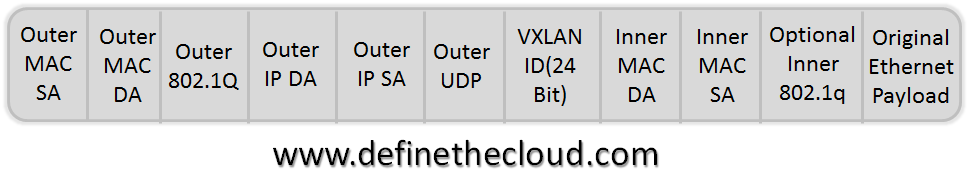
The VXLAN encapsulation method is IP based and provides for a virtual L2 network. With VXLAN the full Ethernet Frame (with the exception of the Frame Check Sequence: FCS) is carried as the payload of a UDP packet. VXLAN utilizes a 24-bit VXLAN header, shown in the diagram, to identify virtual networks. This header provides for up to 16 million virtual L2 networks.
Frame encapsulation is done by an entity known as a VXLAN Tunnel Endpoint (VTEP.) A VTEP has two logical interfaces: an uplink and a downlink. The uplink is responsible for receiving VXLAN frames and acts as a tunnel endpoint with an IP address used for routing VXLAN encapsulated frames. These IP addresses are infrastructure addresses and are separate from the tenant IP addressing for the nodes using the VXLAN fabric. VTEP functionality can be implemented in software such as a virtual switch or in the form a physical switch.
VXLAN frames are sent to the IP address assigned to the destination VTEP; this IP is placed in the Outer IP DA. The IP of the VTEP sending the frame resides in the Outer IP SA. Packets received on the uplink are mapped from the VXLAN ID to a VLAN and the Ethernet frame payload is sent as an 802.1Q Ethernet frame on the downlink. During this process the inner MAC SA and VXLAN ID is learned in a local table. Packets received on the downlink are mapped to a VXLAN ID using the VLAN of the frame. A lookup is then performed within the VTEP L2 table using the VXLAN ID and destination MAC; this lookup provides the IP address of the destination VTEP. The frame is then encapsulated and sent out the uplink interface.

Using the diagram above for reference a frame entering the downlink on VLAN 100 with a destination MAC of 11:11:11:11:11:11 will be encapsulated in a VXLAN packet with an outer destination address of 10.1.1.1. The outer source address will be the IP of this VTEP (not shown) and the VXLAN ID will be 1001.
In a traditional L2 switch a behavior known as flood and learn is used for unknown destinations (i.e. a MAC not stored in the MAC table. This means that if there is a miss when looking up the MAC the frame is flooded out all ports except the one on which it was received. When a response is sent the MAC is then learned and written to the table. The next frame for the same MAC will not incur a miss because the table will reflect the port it exists on. VXLAN preserves this behavior over an IP network using IP multicast groups.
Each VXLAN ID has an assigned IP multicast group to use for traffic flooding (the same multicast group can be shared across VXLAN IDs.) When a frame is received on the downlink bound for an unknown destination it is encapsulated using the IP of the assigned multicast group as the Outer DA; it’s then sent out the uplink. Any VTEP with nodes on that VXLAN ID will have joined the multicast group and therefore receive the frame. This maintains the traditional Ethernet flood and learn behavior.
VTEPs are designed to be implemented as a logical device on an L2 switch. The L2 switch connects to the VTEP via a logical 802.1Q VLAN trunk. This trunk contains an VXLAN infrastructure VLAN in addition to the production VLANs. The infrastructure VLAN is used to carry VXLAN encapsulated traffic to the VXLAN fabric. The only member interfaces of this VLAN will be VTEP’s logical connection to the bridge itself and the uplink to the VXLAN fabric. This interface is the ‘uplink’ described above, while the logical 802.1Q trunk is the downlink.

Summary
VXLAN is a network overlay technology design for data center networks. It provides massively increased scalability over VLAN IDs alone while allowing for L2 adjacency over L3 networks. The VXLAN VTEP can be implemented in both virtual and physical switches allowing the virtual network to map to physical resources and network services. VXLAN currently has both wide support and hardware adoption in switching ASICS and hardware NICs, as well as virtualization software.
In part one of this post I covered the basic theory of operations and functionality of VXLAN (http://www.definethecloud.net/vxlan-deep-dive.) This post will dive deeper into how VXLAN operates on the network.
Let’s start with the basic concept that VXLAN is an encapsulation technique. Basically the Ethernet frame sent by a VXLAN connected device is encapsulated in an IP/UDP packet. The most important thing here is that it can be carried by any IP capable device. The only time added intelligence is required in a device is at the network bridges known as VXLAN Tunnel End-Points (VTEP) which perform the encapsulation/de-encapsulation. This is not to say that benefit can’t be gained by adding VXLAN functionality elsewhere, just that it’s not required.

Providing Ethernet Functionality on IP Networks:
As discussed in Part 1, the source and destination IP addresses used for VXLAN are the Source VTEP and destination VTEP. This means that the VTEP must know the destination VTEP in order to encapsulate the frame. One method for this would be a centralized controller/database. That being said VXLAN is implemented in a decentralized fashion, not requiring a controller. There are advantages and drawbacks to this. While utilizing a centralized controller would provide methods for address learning and sharing, it would also potentially increase latency, require large software driven mapping tables and add network management points. We will dig deeper into the current decentralized VXLAN deployment model.
VXLAN maintains backward compatibility with traditional Ethernet and therefore must maintain some key Ethernet capabilities. One of these is flooding (broadcast) and ‘Flood and Learn behavior.’ I cover some of this behavior here (http://www.definethecloud.net/data-center-101-local-area-network-switching) but the summary is that when a switch receives a frame for an unknown destination (MAC not in its table) it will flood the frame to all ports except the one on which it was received. Eventually the frame will get to the intended device and a reply will be sent by the device which will allow the switch to learn of the MACs location. When switches see source MACs that are not in their table they will ‘learn’ or add them.
VXLAN is encapsulating over IP and IP networks are typically designed for unicast traffic (one-to-one.) This means there is no inherent flood capability. In order to mimic flood and learn on an IP network VXLAN uses IP multi-cast. IP multi-cast provides a method for distributing a packet to a group. This IP multi-cast use can be a contentious point within VXLAN discussions because most networks aren’t designed for IP multi-cast, IP multi-cast support can be limited, and multi-cast itself can be complex dependent on implementation.
Within VXLAN each VXLAN segment ID will be subscribed to a multi-cast group. Multiple VXLAN segments can subscribe to the same ID, this minimizes configuration but increases unneeded network traffic. When a device attaches to a VXLAN on a VTEP that was not previously in use, the VXLAN will join the IP multi-cast group assigned to that segment and start receiving messages.

In the diagram above we see the normal operation in which the destination MAC is known and the frame is encapsulated in IP using the source and destination VTEP address. The frame is encapsulated by the source VTEP, de-encapsulated at the destination VTEP and forwarded based on bridging rules from that point. In this operation only the destination VTEP will receive the frame (with the exception of any devices in the physical path, such as the core IP switch in this example.)

In the example above we see an unknown MAC address (the MAC to VTEP mapping does not exist in the table.) In this case the source VTEP encapsulates the original frame in an IP multi-cast packet with the destination IP of the associated multicast group. This frame will be delivered to all VTEPs participating in the group. VTEPs participating in the group will ideally only be VTEPs with connected devices attached to that VXLAN segment. Because multiple VXLAN segments can use the same IP multicast group this is not always the case. The VTEP with the connected device will de-encapsulate and forward normally, adding the mapping from the source VTEP if required. Any other VTEP that receives the packet can then learn the source VTEP/MAC mapping if required and discard it. This process will be the same for other traditionally flooded frames such as ARP, etc. The diagram below shows the logical topologies for both traffic types discussed.

As discussed in Part 1 VTEP functionality can be placed in a traditional Ethernet bridge. This is done by placing a logical VTEP construct within the bridge hardware/software. With this in place VXLANs can bridge between virtual and physical devices. This is necessary for physical server connectivity, as well as to add network services provided by physical appliances. Putting it all together the diagram below shows physical servers communicating with virtual servers in a VXLAN environment. The blue links are traditional IP links and the switch shown at the bottom is a standard L3 switch or router. All traffic on these links is encapsulated as IP/UDP and broken out by the VTEPs.

Summary:
VXLAN provides backward compatibility with traditional VLANs by mimicking broadcast and multicast behavior through IP multicast groups. This functionality provides for decentralized learning by the VTEPs and negates the need for a VXLAN controller.
Digging Deeper into VXLAN
http://blogs.cisco.com/datacenter/digging-deeper-into-vxlan/
Yes, I am still talking aboutVXLAN, rather you folks are still talking about VXLAN, so I thought its worthwhile digging deeper into the topic since there is so much interest out there. There also still seem to be a fair number of misconceptions around VXLAN, so let’s see what we can do to clear things up.
This time around, I have some partners in crime for the discussion:
Larry Kreeger is currently a Principal Engineer at Cisco Systems’ SAVTG working on Nexus 1000V architecture. Larry has a wide ranging background in networking accumulated from over 25 years of experience in developing networking products. His recent focus is data center networking, especially as it relates to data center virtualization.
Ajit Sanzgiri has worked on various networking technologies at Cisco and other bay area networking companies over the last 16 years. His interests include hardware based switching and routing solutions, Ethernet and wireless LANs and virtual networking. Currently he works on the Nexus1000v and related network virtualization products.
So, Larry and Ajit have put together this VXLAN primer--its fairly dense stuff, so we are breaking this into three posts. In this initial post, we’ll cover the basics--why VXLANs and what is VXLAN. I know I’ve covered this to some degreealready, but Larry and Ajit are going to dig a little deeper, which will hopefully help clarify the lingering questions and misconceptions. In the next post, we’ll discuss how VXLAN compares with the other tools in your networking arsenal, and, in the final post, we’ll cover more of the common questions we are seeing.
1 Why VXLANs ?
VLANs have been used in networking infrastructures for many years now to solve different problems. They can be used to enforce L2 isolation, as policy enforcement points and as routing interface identifiers. Network services like firewalls have used them in novel ways for traffic steering purposes
Support for VLANs is now available in most operating systems, NICs, network equipment (e.g. switches, routers, firewalls etc.) and also in most virtualization solutions. As virtualized data centers proliferate and grow, some shortcomings of the VLAN technology are beginning to make themselves felt.Cloud providers need some extensions to the basic VLAN mechanism if these are to be overcome.
The first is the VLAN namespace itself. 802.1q specifies a VLAN ID to be 12 bits which restricts the number of VLANs in a single switched L2 domain to 4096 at best. (Usually some VLAN IDs are reserved for ‘well-known’ uses, which restricts the range further.) Cloud provider environments require accommodating different tenants in the same underlying physical infrastructure. Each tenant may in turn create multiple L2/L3 networks within their own slice of the virtualized data center. This drives the need for a greater number of L2 networks.
The second issue has to do with the operational model for deploying VLANs. Although VTP exists as a protocol for creating, disseminating and deleting VLANs as well as for pruning them for optimal extent, most networks disable it. That means some sort of manual coordination is required among the network admin, the cloud admin and the tenant admin to transport VLANs over existing switches. Any proposed extension to VLANs must figure out a way to avoid such coordination. To be more precise, adding each new L2 network must not require incremental config changes in the transport infrastructure.
Third, VLANS today are too restrictive for virtual data centers in terms of physical constraints of distance and deployment. The new standard should ideally be free (at least ‘freer’) of these constraints. This would allow data centers more flexibility in distributing workloads, for instance, across L3 boundaries.
Finally, any proposed extension to the VLAN mechanism should not necessarily require a wholesale replacement of existing network gear. The reason for this should be self-evident.
VXLAN is the proposed technology to support these requirements.
2 What are VXLANs ?
2.1 What’s in a name?
As the name VXLANs (Virtual eXtensible LANs) implies, the technology is meant to provide the same services to connected Ethernet end systems that VLANs do today, but in a more extensible manner. Compared to VLANs, VXLANs are extensible with regard to scale, and extensible with regard to the reach of their deployment.
As mentioned, the 802.1Q VLAN Identifier space is only 12 bits. The VXLAN Identifier space is 24 bits. This doubling in size allows the VXLAN Id space to increase by over 400,000 percent to over 16 million unique identifiers. This should provide sufficient room for expansion for years to come.
VXLANs use Internet Protocol (both unicast and multicast) as the transport medium. The ubiquity of IP networks and equipment allows the end to end reach of a VXLAN segment to be extended far beyond the typical reach of VLANs using 802.1Q today. There is no denying that there are other technologies that can extend the reach of VLANs (Cisco FabricPath/TRILL is just one), but none are as ubiquitously deployed as IP.
2.2 Protocol Design Considerations
When it comes to networking, not every problem can be solved with the same tool. Specialized tools are optimized for specific environments (e.g. WAN, MAN, Campus, Datacenter). In designing the operation of VXLANs, the following deployment environment characteristics were considered for its deployment. These characteristics are based on large datacenters hosting highly virtualized workloads providing Infrastructure as a Service offerings.
- Highly distributed systems. VXLANs should work in an environment where there could be many thousands of networking nodes (and many more end systems connected to them). The protocol should work without requiring a centralized control point, nor without a hierarchy of protocols.
- Many highly distributed segments with sparse connectivity. Each VXLAN segment could be highly distributed among the networking nodes. Also, with so many segments, the number of end systems connected to any one segment is expected to be relatively low, and therefore the percentage of networking nodes participating in any one segment would also be low.
- Highly dynamic end systems. End systems connected to VXLANs can be very dynamic, both in terms of creation/deletion/power-on/off and in terms ofmobility across the network nodes.
- Work with existing, widely deployed network equipment. This translates into Ethernet switches and IP routers.
- Network infrastructure administered by a single administrative domain. This is consistent with operation within a datacenter, and not across the internet.
- Low network node overhead / simple implementation. With the requirement to support very large numbers of network nodes, the resource requirements on each node should not be intensive both in terms of memory footprint or processing cycles. This also means consideration for hardware offload.
2.3 How does it work?
The VXLAN draft defines the VXLAN Tunnel End Point (VTEP) which contains all the functionality needed to provide Ethernet layer 2 services to connected end systems. VTEPs are intended to be at the edge of the network, typically connecting an access switch (virtual or physical) to an IP transport network. It is expected that the VTEP functionality would be built into the access switch, but it is logically separate from the access switch. The figure below depicts the relative placement of the VTEP function.
Each end system connected to the same access switch communicates through the access switch. The access switch acts as any learning bridge does, by flooding out its ports when it doesn’t know the destination MAC, or sending out a single port when it has learned which direction leads to the end station as determined by source MAC learning. Broadcast traffic is sent out all ports. Further, the access switch can support multiple “bridge domains” which are typically identified as VLANs with an associated VLAN ID that is carried in the 802.1Q header on trunk ports. In the case of a VXLAN enabled switch, the bridge domain would instead by associated with a VXLAN ID.

Each VTEP function has two interfaces. One is a bridge domain trunk port to the access switch, and the other is an IP interface to the IP network. The VTEP behaves as in IP host to the IP network. It is configured with an IP address based on the subnet its IP interface is connected to. The VTEP uses this IP interface to exchange IP packets carrying the encapsulated Ethernet frames with other VTEPs. A VTEP also acts as an IP host by using the Internet Group Membership Protocol (IGMP) to join IP multicast groups.
In addition to a VXLAN ID to be carried over the IP interface between VTEPs, each VXLAN is associated with an IP multicast group. The IP multicast group is used as communication bus between each VTEP to carry broadcast, multicast and unknown unicast frames to every VTEP participating in the VXLAN at a given moment in time. This is illustrated in the figure below.

The VTEP function also works the same way as a learning bridge, in that if it doesn’t know where a given destination MAC is, it floods the frame, but it performs this flooding function by sending the frame to the VXLAN’s associated multicast group. Learning is similar, except instead of learning the source interface associated with a frame’s source MAC, it learns the encapsulating source IP address. Once it has learned this MAC to remote IP association, frames can be encapsulated within a unicast IP packet directly to the destination VTEP.
The initial use case for VXLAN enabled access switches are for access switches connected to end systems that are Virtual Machines (VMs). These switches are typically tightly integrated with the hypervisor. One benefit of this tight integration is that the virtual access switch knows exactly when a VM connects to or disconnects from the switch, and what VXLAN the VM is connected to. Using this information, the VTEP can decide when to join or leave a VXLAN’s multicast group. When the first VM connects to a given VXLAN, the VTEP can join the multicast group and start receiving broadcasts/multicasts/floods over that group. Similarly, when the last VM connected to a VXLAN disconnects, the VTEP can use IGMP to leave the multicast group and stop receiving traffic for the VXLAN which has no local receivers.
Note that because the potential number of VXLANs (16M!) could exceed the amount of multicast state supported by the IP network, multiple VXLANs could potentially map to the same IP multicast group. While this could result in VXLAN traffic being sent needlessly to a VTEP that has no end systems connected to that VXLAN, inter VXLAN traffic isolation is still maintained. The same VXLAN Id is carried in multicast encapsulated packets as is carried in unicast encapsulated packets. It is not the IP network’s job to keep the traffic to the end systems isolated, but the VTEP’s. Only the VTEP inserts and interprets/removes the VXLAN header within the IP/UDP payload. The IP network simply sees IP packets carrying UDP traffic with a well-known destination UDP port.
So, that was the first installment--if you have questions, post them as comments and we’ll get back to you.
Hey folks--this is the second of three posts looking a little more closely atVXLAN. If you missed the first post, you can find it here. In this installment we are going to look at the some of the other options out there. Two of the most common questions we see are ”why do I need yet another protocol?” and “can I now get rid of X?” This should help you answer these questions.So, let’s dig in…
3 Comparison with other technologies
3.1 Overlay Transport Virtualization (OTV)
If one were to look carefully at the encapsulation format of VXLAN one might notice that it is actually a subset of the IPv4 OTV encapsulation in draft-hasmit-ovt-03, except the Overlay ID field is not used (and made reserved) and the well-known destination UDP port is not yet allocated by IANA (but will be different).
If one were to look even closer, they would notice that OTV is actually a subset of the IPv4 LISP encapsulation, but carrying an Ethernet payload instead of an IP payload.
Using a common (overlapping) encapsulation for all these technologies simplifies the design of hardware forwarding devices and prevents reinvention for its own sake.
Given that the packet on the wire is very similar between VXLAN and OTV, what is different? OTV was designed to solve a different problem. OTV is meant to be deployed on aggregation devices (the ones at the top of an structured hierarchy of 802.1Q switches) to interconnect all (up to 4094) VLANs in one hierarchy with others either in the same or in another datacenter, creating a single stretched 4K VLAN domain. It is optimized to operate over the capital I Internet as a Data Center Interconnect. Cisco’s latest version is able to interconnect datacenters without relying on IP multicast, which is not always available across the Internet. It prevents flooding of unknown destinations across the Internet by advertising MAC address reachability using routing protocol extensions (namely IS-IS). Each OTV device peers with each other using IS-IS. There is expected to be a limited number of these OTV devices peering with each other over IS-IS (because of where they are placed -- at a layer 2 aggregation point). Within a given layer 2 domain below this aggregation point, there are still only 4K VLANs available, so OTV does not create more layer 2 network segments. Instead it extends the existing ones over the Internet.
Since VXLAN is designed to be run within a single administrative domain (e.g. a datacenter), and not across the Internet, it is free to use Any Source Multicast (ASM) (a.k.a. (*,G) forwarding) to flood unknown unicasts. Since a VXLAN VTEP may be running in every host in a datacenter, it must scale to numbers far beyond what IS-IS was designed to scale to.
Note that OTV can be complimentary to VXLANs as a Data Center Interconnect. This is helpful in two ways. For one, the entire world is not poised to replace VLANs with VXLANs any time soon. All physical networking equipment supports VLANs. The first implementations of VXLANs will be only in virtual access switches (the ones Virtual Machines connect to), so this means that only VMs can connect to VXLANs. If a VM wants to talk with a physical device such as a physical server, layer 3 switch, router, physical network appliance, or even a VM running on a hypervisor that does not support a VXLAN enabled access switch -- then it must use a VLAN. So, if you have a VM that wants to talk with something out on the Internet…it must go through a router, and that router will communicate with the VM over a VLAN. Given that some VMs will still need to connect to VLANs, they will still exist and if layer 2 adjacency is desired across datacenters, then OTV works well to interconnect them. The layer 2 extension provided by OTV can be used, not just to interconnect VLANs with VMs and physical devices connected to them, but also by VTEPs as well. Since VTEPs require the use of ASM forwarding, and this may not be available across the Internet, OTV can be used to extend the transport VLAN(s) used by the VTEPs across the Internet between multiple datacenters.
3.2 MAC-in-GRE
Why did VXLANs use a MAC-in-UDP encapsulation instead of MAC-in-GRE? The easy answer is to say, for the same reasons OTV and LISP use UDP instead of GRE. The reality of the world is that the vast majority (if not all) switches and routers do not parse deeply into GRE packets for applying policies related to load distribution (Port Channel and ECMP load spreading) and security (ACLs).
Let’s start with load distribution. Port Channels (or Cisco’s Virtual Port Channels) are used to aggregate the bandwidth of multiple physical links into one logical link. This technology is used both at access ports and on inter-switch trunks. Switches using Cisco’s FabricPath can get even greater cross-sectional bandwidth by combining Port Channels with ECMP forwarding -- but only if the switches can identify flows (this is to prevent out-of-order delivery which can kill L4 performance). If one of today’s switches were to try to distribute GRE flows between two VTEPs that used a GRE encapsulation, all the traffic would be polarized to use only one link within these Port Channels. Why? Because the physical switches only see two IP endpoints communicating, and cannot parse the GRE header to identify the individual flows from each VM. Fortunately, these same switches all support parsing of UDP all the way to the UDP source and destination port numbers. By configuring the switches to use the hash of source IP/dest IP/L4 protocol/source L4 port/dest L4 port (typically referred to as a 5-tuple), they can spread each UDP flow out to a different link of a Port Channel or ECMP route. While VXLAN does use a well-known destination UDP port, the source UDP port can be any value. A smart VTEP can spread the all the VMs 5-tuple flows over many source UDP ports. This allows the intermediate switches to spread the multiple flows (even between the same two VMs!) out over all the available links in the physical network. This is an important feature for data center network design. Note that this does not just apply to layer 2 switches, since VXLAN traffic is IP and can cross routers as well, it applies to ECMP IP routing in the core as well.
Note that MAC-in-GRE based schemes can perform a similar trick as mentioned above by creating flow-based entropy within a sub-portion of the GRE key (as opposed to the source UDP port), but it is a moot point unless all the switches and routers along the path can parse the GRE Key field and use it to generate a hash for Port Channel / ECMP load distribution
Next comes security. As soon as you start carrying your layer 2 traffic over IP routers, you open yourself up for packet injection on to a layer 2 segment from anywhere there is IP access…unless you use firewalls and/or ACLs to protect the VXLAN traffic. Similar to the load balancing issue above, if GRE is used, firewalls and layer 3 switches and routers with ACLs will typically not parse deeply into the GRE header enough to differentiate one type of tunneled traffic from another. This means all GRE would need to be blocked indiscriminately. Since VXLAN uses UDP with a well-known destination port, firewalls and switch/router ACLs can be tailored to block only VXLAN traffic.
Note that one downside to any encapsulation approach, whether it is based on UDP or GRE is that by having the hypervisor software add an encapsulation, today’s NICs and/or NIC drivers do not have a mechanism to be informed about the presence of the encapsulation for performing NIC hardware offloads. It will be a performance benefit for either of these encapsulation methods for NIC vendors to update their NICs and/or NIC drivers and for hypervisor vendors to allow access to these capabilities. Given that NIC vendors (Intel, Broadcom and Emulex) have given public support to both VXLAN and GRE based encapsulations, I can only guess that support for both schemes will be forthcoming.
3.3 LISP
Locator/ID Separation Protocol (LISP) is a technology that allows end systems to keep their IP address (ID) even as they move to a different subnet within the Internet (Location). It breaks the ID/Location dependency that exists in the Internet today by creating dynamic tunnels between routers (Ingress and Egress Tunnel Routers). Ingress Tunnel Routers (ITRs) tunnel packets to Egress Tunnel Routers (ETRs) by looking up the mapping of an end system’s IP address (ID) to its adjacent ETR IP address (Locator) in the LISP mapping system.
LISP provides true end systemmobility while maintaining shortest path routing of packets to the end system. With traditional IP routing, an end station’s IP address must match the subnet it is connected to. While VXLAN can extend a layer 2 segment (and therefore the subnet it is congruent with), across hosts which are physically connected to different subnets, when a VM on a particular host needs to communicate out through a physical router via a VLAN, the VMs IP address must match the subnet of that VLAN -- unless the router supports LISP.
If a VXLAN is extended across a router boundary, and the IP Gateway for the VXLAN’s congruent subnet is a VM on the other side of the router, this means traffic will flow from the originating VMs server, across the IP network to the IP Gateway VM residing on another host, and then back up into the physical IP network via a VLAN. This phenomenon is sometime referred to as “traffic tromboning” (alluding to the curved shape of a trombone). Thus, while VXLANs support VMs moving across hosts connected to different layer 2 domains (and therefore subnets), it doesn’t provide the direct path routing of traffic that LISP does.
3.4 MAC-in-MAC
VMware has an existing proprietary equivalent of VXLAN which is deployed today with vCloud Director, called vCloud Director Network Isolation (vCDNI). vCDNI uses a MAC-in-MAC encapsulation. Cisco and VMware, along with others in the hypervisor and networking industry have worked together on a common industry standard to replace vCDNI -- namely VXLAN. VXLAN has been designed to overcome the shortcomings of the vCDNI MAC-in-MAC encapsulation -- namely load distribution, and limited span of a layer 2 segment.
The first one is the same issue that GRE has with load distribution across layer 2 switch Port Channels (and ECMP for FabricPath). The second is that because the outer encapsulation is a layer 2 frame (not an IP packet), all network nodes (hypervisors in the case vCDNI), MUST be connected to the same VLAN. This limits the flexibility in placing VMs within your datacenter if you have any routers interconnecting your server pods unless you use a layer 2 extension technology such as OTV to do it.
So, a couple of points to wrap things up. Hopefully, this gives you a better understanding of why VXLAN instead of some of the existing options. Beyond that, I hope it becomes clear that while VXLAN is immensely useful, it is not magical--it relies on a well-built, well-operating L2/L3 infrastructure so other technologies and protocols are going to come into play in the real world. As usual, post questions to either of these blog entires and we will get them answered as best we can.
So, here is our final installment--we are wrapping up with some of the more common questions were are seeing. In you missed the earlier posts, be sure to check outPart 1 and Part 2. I also have a couple of earlier posts introducing VXLAN and answering some of the initial questions.
So, onto the FAQs…
How do VXLANs relate to VN-tags ?
Some people have asked what is the relationship between VN-tags (aka 802.1Qbh) and VXLANs. Does one rule out the other ? The answer is a definite ‘no’. The VN-tag exists on the link between a VM and the virtual switch (or ‘VM-switch’). If such a switch has support for VXLANs then the VMs in question can get connectivity through VXLANs. A packet will never need to have both at the same time. In the context of Cisco products, VM-FEX technology remains complementary to VXLANs.
So now we can migrate VMs across subnets ?
There is also some confusion over what implications VXLANs have for VMmobility. Claims such as “VXLANs permit mobility across L3 boundaries” have been taken to mean different things.
We want to make clear that VMs connected to VXLANs do not need to change their own IP addresses as a consequence of this technology. Essentially, VMs connected to a VXLAN remain unaware that they are on a VXLAN -- just as they are usually unaware of running on VLANs. It is up to the underlying network to ensure connectivity between such VMs and provide layer-2 semantics such as mac-layer broadcast and unicast traffic. As a consequence, any mobility event -- live or otherwise -- has no effect on the internals of the VM.
At the same time, since the native Ethernet frames are carried over an IP encapsulation, the tunnel endpoints themselves do not need to be on the same VLAN or IP subnet in order to ensure connectivity of the VXLAN. This creates the potential for a VM on a certain VXLAN to move between hosts which are themselves on different subnets. It is important however not to interpret this to mean live VM migration is now immediately possible across subnets, since other factors can get in the way. As an example, live VM migration itself requires transfer of VM data between two hosts. This transfer may not be possible or officially supported across subnets. All that VXLANs ensure is connectivity to the same perceived layer 2 broadcast network regardless of which host it is on (assuming of course that the network supports VXLANs) and regardless of which subnet the host connects to. However, VXLANs do not, by themselves, circumvent other impediments to live VM migration -- such as the transfer issue mentioned above.
What about routing across VXLANs ?
So, you are thinking “This is all well and good to interconnect VMs at layer-2 in a scalable way, but how do they talk to the real world of corporate networks and the internet” ? In other words, who routes between VXLANs ? Or between VXLANs and VLANs or VXLANs and the global internet ?
The answer to this will evolve over time just as it did with VLAN technology. If a router is ignorant of 802.1Q tagging it cannot route across VLANs unless someone else terminates VLAN tagging on its behalf. For instance an 802.1Q-capable L2 switch can strip the tag and forward native Ethernet frames to/from the router. The router would then only support one “VLAN interface” on each physical interface.
With VXLANs, too, VXLAN capable devices could take the responsibility for stripping the encapsulation before forwarding the packet to the router for routing. If VXLAN functionality remains confined to virtual switches, the router, too, will need to be a virtual router i.e. routing software running inside a VM. As and when non-virtual physical switches support the VXLAN format, real physical router boxes can connect to them. Of course, as in the VLAN case, this will limit the number of routable VXLAN interfaces on the router. A better solution would be for the router itself to encap/decap the VXLAN tunneled packets so it can support a large number of VXLAN interfaces on the same physical interface.
One intermediate step between using purely virtual routers and having physical routers support the VXLAN encapsulation would be for the L2 network to permit bridging between VXLANs and VLANs. This will allow both physical and virtual devices -- whether routers or other nodes -- to connect into VXLANs without requiring an upgrade to their software. Such a bridging functionality is defined in theproposed draft standard for just such purposes.
In many cloud provider environments, tenants may be able to directly create VXLANs within their portion of the public data center (sometimes called an Organization’s Virtual Data Center). The IP addressing of the tenant-administered VMs on these VXLANs will in general not be coordinated across different tenants. This makes NAT a very desirable feature on the router or routers directly attached to such client administered VXLANs. Ditto for VPN connectivity to the tenant’s own network.
Are VXLANs secure ?
With proper precautions they can be just as secure as regular networks. It is true however, that there is a greater risk of attacks and users must understand this and take measures to guard against it. In the worst case, an attacker can inject himself into a VXLAN by sending IP-encapsulated packets from anywhere. Of course this requires access to the IP network. A first line of defense is to have a perimeter firewall that denies IP traffic with the VXLAN encapsulation from the outside.
This does not prevent attacks from the inside. For that users would need to control access at internal routers to ensure that only authorized tunnel endpoints can inject packets into VXLAN tunnels. This can be done statically (knowing the physical topology of the network) or by employing additional IP security mechanisms that guarantee encryption and/or authentication.
Rather than re-invent this particular wheel, the VXLAN draft lets users make use of existing methods to secure VXLAN tunneled traffic, while pointing out where the risks lie.
What about network services ?
Since VXLANs are expected to be deployed in hosted environments people naturally want to know how to enable network services (firewalls, IPS, load balancing, WAN optimization) for VXLANs. The answer to this is pretty much the same as for routers. Either the services need to be enabled in endpoints that can be attached to VXLANs (i.e. virtual in the immediate future), or these services need to become VXLAN aware or someone needs to perform a bridging function between VXLANs and whatever it is that the services understand (physical interfaces, VLANs etc.)
So, if you are intrigued by VXLANs, you may want to ping you Cisco account team--we will be kicking off a closed beta soon.
Openstack Neutron using VXLAN
The networking part of Openstack provides several models for the L2 networks to be used as L2 tenant broadcast domains. An overlay network can be used to separate the MAC addresses and “vlans” of the tenant networks from the transport layer network.
Openstack neutron in Havana supports two overlay network technologies, GRE and VXLAN. VXLAN is my preferred solution, because it provides more entropie on the receiving NIC, which results in a higher performance, because multiple CPU cores are used to process ingress packets.
In this article I’ll show the implementation of VXLAN on three nodes. Two nodes are used as compute hosts, one node is used as the network node. On the network node (NN) several Neutron agents are running:
- L3 agent: This one is responsible to build tenant routers using Linux network namespaces
- DHCP agent: This one is responsible to build DHCP servers for tenant networks using Linux network namespaces
- L2 (OVS) agent: This one configures and provisions the OVS
The Neutron metadata services is also deployed to provide cloudinit support for started VMs.
On the compute nodes (CN), only the L2 (OVS) agent is necessary.
A typical Openstack deployment is using one instance of the OVS, br-int, as the point to connect all VMs, DHCP servers and the “non default gateway” side of all routers. br-int is using classic Vlans to separate the broadcast domains.
br-tun is a second OVS instance, and is used to provide the VXLAN function. br-tun is connected to br-int via an internal link. This links is a trunking port, it is using dot1q tagging to transport vlan ids-
When configuring Openstack Neutron (Havana not using ML2 ) I recommend to change the value of the tunnel ids in the neutron config to:
tunnel_id_ranges = 65537:69999
Changing this from the default values, which are below 4096, has the great advantage, that it easy to distinguish vlans ids from vxlan tunnel ids. This helps to understand the Openflow rules provisioned by neutron on br-tun. Why using 65537 as the first tunnel id? Well, 65537 in hex is 0×10001 and the OVS shows tunnel ids as hex values. It’s easy to read….
When using Openstack Icehouse on Ubuntu with ML2, the openvswitch plugin is not longer used. Any openvswitch config must be put in the ml2 plugin config file, using the section “ovs”.
/etc/neutron/plugins/ml2/ml2_conf.ini
[ml2]
type_drivers = vxlan,local
tenant_network_types = vxlan
mechanism_drivers = openvswitch
[ml2_type_vxlan]
vni_ranges = 65537:69999
[ml2_type_gre]
tunnel_id_ranges = 32769:34000
[ovs]
local_ip = <set IP for the tunnelinterface>
tunnel_type = vxlan
tunnel_bridge = br-tun
integration_bridge = br-int
tunnel_id_ranges = 65537:69999
tenant_network_type = vxlan
enable_tunneling = true
[agent]
root_helper = sudo neutron-rootwrap /etc/neutron/rootwrap.conf
tunnel_types = vxlan
vxlan_udp_port = 4789
l2_population = False
[securitygroup]
enable_security_group = True
firewall_driver = neutron.agent.linux.iptables_firewall.OVSHybridIptablesFirewallDriver
My recommendation is, to use different ranges for vlans, vxlan tunnelid’s (vni’s) and gre id’s.
This leads to the following setup as shown in the drawing (without showing the second compute node), which is using eth1 as the IP interface to transport the VXLAN traffic and br-ex to attach the routers to the public address pool 198.18.1.0/24.

On the VXLAN transport network it is very important to use jumbo frames. If you choose 1600 instead of the default 1500 you’re on the safe side. The VXLAN tunnel overlay requires an additional UDP header on top of a full sized ip packet. Without jumbo frames the performance of GRE and VXLAN overlays drop to less than 100 MBit/s – instead of using 10 GBit/s and more. This performance drop is caused by the required packet fragmentation and defragmentation CPU processing needed on the sending and receiving side of the tunnel.
br-tun Openflow rules
Now we take a look at br-tun. First we get the ports using the commandovs-ofctl show br-tunand a following grep to filter unnecessary output.
ovs-ofctl show br-tun | grep -v -E "REPLY|n_tables|capabilities:|actions:|config:|state:"
1(patch-int): addr:6e:72:61:71:d9:02
speed: 0 Mbps now, 0 Mbps max
2(vxlan-2): addr:ee:bb:80:d1:90:0a
speed: 0 Mbps now, 0 Mbps max
3(vxlan-3): addr:f2:be:77:6f:66:e6
speed: 0 Mbps now, 0 Mbps max
LOCAL(br-tun): addr:1e:8c:fc:76:b2:4b
speed: 0 Mbps now, 0 Mbps max
br-tun has three ports:
- port 1 is the connection to br-int
- port 2 is the connection to compute node 1
- port 2 is the connection to compute node 2
- port LOCAL is an internal OVS port
The openflow rules can be shown using the commandovs-ofctl dump-flows br-tun:
ovs-ofctl dump-flows br-tun
NXST_FLOW reply (xid=0x4):
cookie=0x0, duration=1806.214s, table=0, n_packets=0, n_bytes=0, idle_age=1806, priority=1,in_port=1 actions=resubmit(,1)
cookie=0x0, duration=1044.587s, table=0, n_packets=0, n_bytes=0, idle_age=1044, priority=1,in_port=3 actions=resubmit(,3)
cookie=0x0, duration=1320.063s, table=0, n_packets=0, n_bytes=0, idle_age=1320, priority=1,in_port=2 actions=resubmit(,3)
cookie=0x0, duration=1806.18s, table=0, n_packets=0, n_bytes=0, idle_age=1806, priority=0 actions=drop
cookie=0x0, duration=1806.114s, table=1, n_packets=0, n_bytes=0, idle_age=1806, priority=0,dl_dst=01:00:00:00:00:00/01:00:00:00:00:00 actions=resubmit(,21)
cookie=0x0, duration=1806.146s, table=1, n_packets=0, n_bytes=0, idle_age=1806, priority=0,dl_dst=00:00:00:00:00:00/01:00:00:00:00:00 actions=resubmit(,20)
cookie=0x0, duration=1806.082s, table=2, n_packets=0, n_bytes=0, idle_age=1806, priority=0 actions=drop
cookie=0x0, duration=1806.049s, table=3, n_packets=0, n_bytes=0, idle_age=1806, priority=0 actions=drop
cookie=0x0, duration=1806.017s, table=10, n_packets=0, n_bytes=0, idle_age=1806, priority=1
actions=learn(table=20,hard_timeout=300,priority=1,
NXM_OF_VLAN_TCI[0..11],NXM_OF_ETH_DST[]=NXM_OF_ETH_SRC[],
load:0->NXM_OF_VLAN_TCI[],load:NXM_NX_TUN_ID[]->NXM_NX_TUN_ID[],
output:NXM_OF_IN_PORT[]),output:1
cookie=0x0, duration=1805.985s, table=20, n_packets=0, n_bytes=0, idle_age=1805, priority=0 actions=resubmit(,21)
cookie=0x0, duration=1805.953s, table=21, n_packets=0, n_bytes=0, idle_age=1805, priority=0 actions=drop
The Openflow rules shown, use different tables. table 0 is processed as the first one. Each table has rules with different priorities, the rules with the highest priority are checked first. At this stage, the rules do not make much sense.
The output below shows the checks done for an unicast packet entering from port=1.

Openflow rules after the installation or br-tun
As we have seen above, port 1 is the port to br-int. Any packet entering port 1 is resubmitted to table 1. The first rule of table 1 checks if the packet is a multicast or broadcast ethernet packet. As we have an unicast packet, the rule does not match. The next rule is true for all unicast ethernet packets, so the packet is resubmitted to table 20. We have at this stage only one rule in table 20 and the action is resubmit to table 21. In table 21 the packet is dropped, because the action is drop.
At this stage, br-tun drops all traffic entering on one of the three ports. This is fine, as we did not configure anything as a tenant within Openstack.
Add a router, one network and one subnet.
Now it ‘s time to add networking from the tenant’s perspective within Openstack. The tasks are:
- Add a router
- Connect the router to the public network by setting a default gateway
- Add a network as a broadcast domain
- Add a subnet to the network. Within Openstack a subnet is an IP network.
The router is deployed as a Linux network namespace on the network node, as soon as there is an interfaces connected to the router. Do not use any agent stuff without enabled network namespaces. The first interface we added to the router in our example is the default gateway.
VXLAN to Vlan mapping
After creating the tenant network, the Openflow rules on the nodes for br-tun looks like:

Openflow rules on br-int after creating one tenant network
Two rules have been added:
- In Openflow table 3 a rule has been added to map the globally unique tunnel_id to the vlan_id, which has only node local scope. Any traffic which matches this rule is forwarded to Openflow table 10. The action of the first rule of Openflow table 10 has two actions. The first one performs MAC learning and inserts the learned MAC addresses together with a vlan_id to tunnel_id mapping and the egress vlxlan port to Openflow table 20. Openflow table 20 is used for egress traffic. The second action is to output the traffic to Openflow port 1, which is the port to br-int.
- In Openflow table 21 a rule has been added to map the local vlan_id to the global tunnel_id. This rule is only used for broadcast, multicast or unknown unicast traffic. Unknown unicast traffic is flooded by default. These packets are sent by default to ALL nodes in the vxlan mesh. This is a very bad behaviour. The network implementation does not support VLAN pruning.
Start a VM on compute node 1
After starting a VM on compute node 1, the Openflow table on br-tun looks like.

Openflow rules on the compute node after learning the MAC addresses of the DHCP server and the router
Openflow table 20 contains two new rules, which have been inserted by the learning action of the Openflow rule in table 10. The two new rules contain the MAC addresses of the router and the DHCP server. Port 2 is the VXLAN tunnel to Compute node 1.
On the network node, a similar learned Openflow rule appears in table 20. This rule contains the MAC address of the VM.
Unicast packet transmission from the VM on the compute node
When the started VM on the compute node transmits a packet with the destination “router MAC address”, the walk through the Openflow rules on br-tun looks like:

Openflow rule walktrough when the VM transmits an unicast packet to the router MAC
- The packet enters br-tun on port 1, which is the connection to br-int. The first prio=1 rule of table 0 matches and the packet is resubmitted to table 1.
- In table 1 the second rule matches, because the packet is an unicast packet. The packet is resubmitted to table 20, which is the table for learned MAC addresses.
- In table 20 the first rule of priority=1 matches, because of the destination MAC address. The action sets the tunnel_id to 0×10001, sets the vlan_id to zero (which removes the vlan dot1q tag) and transmits the packet through port 2, which is the vxlan virtual port to the network node.
Any packet entering table 20, which does NOT match any of the rules with priority=1 is processed by the priority=0 rules of table 20 and resubmitted to table 21. The prio=1 rule in table 21 “floods” the packet to ALL nodes in the mesh using unicast.
Packet sent to the VM
When the started VM on the compute node receives a packet, the walk through the Openflow rules on br-tun looks like:

Openflow rule walkthrough when a packet is transmitted to the VM
- The packet enters br-tun on port 2, which is the vxlan connection to the network node. The third prio=1 rule of table 0 matches and the packet is resubmitted to table 3.
- In table 3 the first rule matches, because the tunnel_id is 0×10001. The vlan_id of the packet is set to 1 (which is the local vlan_id for the global tunnel_id). The packet is resubmitted to table 10
- In table 10 the only rule is processed. This rule has two actions. Action one performs MAC learning. If the MAC address of the sender is not in the MAC learning Openflow table 20, it is added to the table including the mapping tunnel_id to vlan_id. The second action is to transmit the packet out of port 1, which is the port to br-int.
Conclusion
The implementation of the vxlan mesh in Openstack Havana is straight forward. It provides a working L2 connectivity when running IPV4. Anyhow, it misses features, which are delivered even with cheap hardware switches. These are:
- no Vlan pruning. It is quite simple to overflow the whole infrastructure using broadcast traffic (or multicast traffic). Traffic replication for target systems reachable only via vxlan tunnels, is done on the egress Openvswitch. This does not scale in large environments (>> 30 nodes)
- no IGMP and MLDv2 snooping. Together with the missing Vlan pruning, this makes it impossible to run applications which require IP multicast.
To optimize the traffic handling other features must be implemented to allow scaling to high node numbers.
- MAC preprovisioning (addressed by ML2 and/or Openstack Icehouse) to avoid flooding of traffic
- ARP preprovisioning to avoid flooding of traffic
- preprovisioned IPV6 neighbor entries to avoid flooding of traffic
- use a multicast address to flood traffic (addressed by Openstack Icehouse), but still no Vlan pruning
- support IGMP and MLDv2 snooping on the OVS
- support the mapping of multicast traffic in the overlay network to PIM-SSM in the underlay network
Is VXLAN the Answer to the Network Virtualization Question?
Network virtualization is a growing topic of interest and for some good reasons as networks scale to meet the challenges of cloud computing they are running up against VLAN scaling limitations. There have been several network overlay technologies released that seek to address the challenges with network scaling and to enable workload mobility. One of these technologies is VXLAN. It has a few proponents who say that it can meet the requirements for network virtualization. While it sounds good on the surface, it is worth it to take a closer look. With VMWorld happening this week in San Francisco I’m sure that network virtualization will be a hot topic, especially considering the VMware Nicera news, so I thought I’d comment on it and offer some thoughts and options.
The Origins of VXLAN
The VXLAN buzz started during a keynote at VMworld in August 2011, when VMware CTO Steve Herrod announced the Virtual eXtensible LAN protocol, which VMware positions as a technology that “enables multi-tenant networks at scale, as the first step towards logical, software-based networks that can be created on-demand, enabling enterprises to leverage capacity wherever it’s available. Networking vendors Cisco and Arista are actively promoting VXLAN and have collaborated with VMware to develop and test the technology on their products. Cisco highlighted VXLAN at their Cisco Live user conference again in June 2012 and Arista is demoing it at VMWorld, however with the Nicira announcement VMWare seems to have taken that next step. VXLAN sounds interesting, so let's see how good of an idea it is.
What VXLAN Is and What it Does
VXLAN is a new framework that requires the creation of overlay networks for virtual machines (VMs) to communicate with each other and/or to move VMs over an overlay network both within a data center and between data centers. VXLAN implements a Layer 2 network isolation technology that uses a 24-bit segment identifier to scale beyond the 4K limitations of VLANs. VXLAN technology creates LAN segments by using an overlay approach with MAC in IP encapsulation. Vendors who promote VXLAN say that traditional data center/cloud networks fall short in two key areas and VXLAN will solve these issues:
1. Multi-Tenancy IaaS Scalability: Network isolation technologies such as VLAN and VRF may not provide enough network segments for large cloud deployments.
2. Virtual Machine Mobility: Layer 3 boundaries create silos that virtual machines (VMs) cannot cross, limiting the scalability of the VM resource pools that cloud deployments rely on.
The primary goals behind this network architecture are to:
1. Increase traditional VLAN limits from 4,094 to a larger, as yet undetermined, number of virtual networks in a multi-tenant (Cloud IaaS) deployment.
2. Enable VM mobility across Layer 3 subnets as cloud deployments grow into multiple L3 subnets.
The proposed solution is a new protocol, VXLAN, which is captured in an IETF draft version 00, see linkhttp://tools.ietf.org/html/draft-mahalingam-dutt-dcops-vxlan-00. The proposal is still in an experimental state and there is no confirmed date for ratification.
Some Issues with VXLAN
Multicast: A complicating aspect is that VXLAN expects multicast to be enabled on physical networks, and it does MAC flooding to learn end points.This will impact the performance and scalability of existing physical network segments in the data center, and over the WAN, creating design, scalability and operational challenges.
Overlay Tunnels: Since VXLAN is an overlay tunnel, it adds a layer to the network that must be managed, and creates operational and scaling challenges. It imposes new end-points, usually a vSwitch, that takes the L2 frames from the VMs, encapsulate them and attaches an IP header. VXLAN creates considerations around what the IP address termination device should be.
Lack of Control Plane: Most of the control plane complexities such as segment ID allocation, and multi-cast are not addressed by VXLAN. To solve these issues you need a control plane, but VXLAN does not have one so it puts the problem on the network. A control plane mechanism is needed to solve this problem. The question is if it should be an SDN controller or the router.
Tunnels in Tunnels: Interoperability with the widely used VPLS/MPLS network segmentation scheme is not yet defined with VXLAN and VXLAN tunnels can’t prevent themselves from being tunneled further, creating complexity as well as a lack of visibility in to network traffic, hindering application performance management, as well as potentially impacting the benefits of VXLAN.
Security: VXLAN security is not addressed in the draft yet. Typically, security for overlay protocols is addressed with IPSec tunnels. This will add additional overhead and the solutions will become burdensome to implement and manage.
Scalability: The VXLAN overlay network originates from a VM on a server at the software level and this could impact overall performance as administrators scale their VM deployments. In addition, many best practices and protocols developed for physical infrastructure need to be replicated for VXLAN in software, adding more performance and scalability challenges. Potentially this process should be off loaded to the physical switch using a technology such as VEPA.
Physical Devices: A challenge with the end points being vSwitches is that you can only connect virtual ports to VXLAN segments, so you can’t connect your physical firewall, server load balancer, or router directly. You have to use virtualized versions that run in VMs, so performance could be an issue and you need to manage server load. Deploying virtualized appliances has some advantages but we still need to sort out interoperability with the physical network.
Some Consideration and Takeaways
The ability to stretch L2 adjacencies to accommodate the live migration of VMs is considered important for IaaS. Currently the viable construct to provide isolation / separation for L2 is the VLAN, so a large number of VLANs is seen as desirable. Most network switching equipment only supports 4,096 VLANs, however, several of Juniper’s product lines scale beyond the VLAN limitation. The MX Series routers support 256,000 VLANs for example. There are ways to overcome VLAN limitations such as QinQ, or VLAN stacking, vCDNI, and Provider Backbone Bridging.
Preservation of private IP subnets while enabling VM mobility across Layer 3 boundaries is seen as desirable for large-scale cloud deployments. Juniper provides technologies that enable L2 stretch like Virtual Chassis on the Juniper EX systems and VPLS on the MX series and the QFabric System, with integrated L2 and L3, which scales massively .
VXLAN does not have a control plane and it uses multi-cast to flood the network for endpoint discovery, so it poses control plane scalability and network manageability issues. This could be addressed by integrating VXLAN with an SDN controller or by deploying another overlay tunneling protocol that is managed from an SDN controller instead. There are a number of such devices on the market and Juniper is evaluating some of them for interoperability with our equipment.
Since it runs in the hypervisor VXLAN uses shared resources and performance cannot be guaranteed. A method is needed to ensure priority allocation of compute resources in a hypervisor environment if this type of technology is going to scale or the tunnel processing needs to be offloaded to the physical switch perhaps using VEPA technology. Juniper partners with IBM that provides a VEPA enable soft switch for example and Juniper has included VEPA in JUNOS 12.1.
At Juniper we continue to evaluate the overlay network technology as it evolves and we are working to find answers that fit the needs of our customers as we develop technologies to support network virtualization. We are taking a close look at VXLAN and the value that it can deliver for our customer's networks.
I know that I have not covered everything but I hope that this post has provided some valuable information to help you evaluate your technology choices and see the value that VXLAN can bring to your network.
Scalable Cloud Networking with Cisco Nexus 1000V Series Switches and VXLAN
What You Will Learn
Many enterprise and service provider customers are building private or public clouds. Intrinsic to cloud computing is the presence of multiple tenants with numerous applications using the on-demand cloud infrastructure. Each of these tenants and applications needs to be logically isolated from the others, even at the network level. For example, a three-tier application can have multiple virtual machines in each tier and requires logically isolated networks between these tiers. Traditional network isolation techniques such as IEEE 802.1Q VLAN provide 4096 LAN segments (through a 12-bit VLAN identifier) and may not provide enough segments for large cloud deployments.
Cisco and a group of industry vendors, including VMware, Citrix, and Red Hat, are working together to address new requirements for scalable LAN segmentation and for transport of virtual machines across a broader network range. The underlying technology, referred to as Virtual Extensible LAN (VXLAN), defines a 24-bit LAN segment identifier that provides segmentation at cloud scale. In addition, VXLAN provides an architecture that customers can use to expand their cloud deployments with repeatable pods in different Layer 2 domains. VXLAN can also enable migration of virtual machines between servers across Layer 3 networks. With Cisco Nexus® 1000V Series Switches supporting VXLAN, customers can quickly, confidently, and securely deploy their applications in a multi‑tenant cloud infrastructure.
Cloud Computing Demands More Logical Networks
An infrastructure for a service cloud computing environment can have a large number of tenants, each with its own applications. In fact, each tenant requires a logical network isolated from all other tenants. Furthermore, each application from a tenant also requires its own logical network, to isolate it from other applications. To provide instant provisioning, cloud management tools, such as VMware vCloud Director, clone the application’s virtual machines, including the virtual machines’ network addresses, that demands a logical network for each instance of the application.
Challenges of Existing Network Isolation Techniques
The VLAN has been the traditional mechanism for providing logical network isolation. Because of the ubiquity of the IEEE 802.1Q standard, numerous switches and tools are available that provide robust network troubleshooting and monitoring capabilities, enabling mission-critical applications to depend on the network. The IEEE 802.1Q standard specifies a 12-bit VLAN identifier, which limits the scalability of cloud networks beyond 4K VLANs. Some in the industry have proposed incorporation of a longer logical network identifier in a MAC-in-MAC or MAC in Generic Route Encapsulation (MAC-in-GRE) encapsulation as a way to expand scalability. Unfortunately, these techniques transport network packets inefficiently because they cannot make use of all the links in a PortChannel, which is typically implemented in data center networks.
VXLAN Solution
VXLAN meets these challenges with a MAC in User Datagram Protocol (MAC-in-UDP) encapsulation technique and a 24-bit segment identifier in the form of a VXLAN ID (Figure 1). The larger VXLAN ID allows LAN segments to scale to 16 million in a cloud network. In addition, the UDP encapsulation allows each LAN segment to be extended across Layer 3 and helps ensure even distribution of traffic across PortChannel links (see Figure 2 later in this document).
VXLAN uses an IP multicast network to send broadcast, multicast, and unknown unicast flood frames. When a virtual machine joins a VXLAN segment, the server joins a multicast group. Broadcast traffic from the virtual machine is encapsulated and is sent using multicast to all the servers in the same multicast group. Subsequent unicast packets are encapsulated and unicast directly to the destination server without multicast. In effect, traditional switching takes place within each VXLAN segment.
Figure 1. VXLAN Packet Format

The VXLAN solution provides these capabilities:
● Logical networks can be extended among virtual machines placed in different Layer 2 domains (Figure 2).
● Flexible, scalable cloud architecture enables addition of new server capacity over Layer 3 networks and accommodates elastic cloud workloads (Figure 2).
● If a virtual machine is connected only through VXLAN, then it can migrate across the Layer 3 network (gray virtual machine in Figure 3).
● If a virtual machine is connected to a VLAN (as in the case of the red virtual machine with VLAN and VXLAN connections in Figure 3), then it is restricted to migration within the Layer 2 domain. Note that a virtual machine on a VXLAN segment needs to be connected to a VLAN network in order to interact with external networks. To migrate such a virtual machine across Layer 3, you can use Overlay Transport Virtualization (OTV), discussed in more detail later in this document.
Figure 2. Segmentation with VXLAN

Figure 3. Migration Range with VLAN and VXLAN

Since VXLAN is a tunneling technique, the VXLAN gateway is required to send traffic to and from VXLAN to a traditional VLAN. In fact, for VXLAN traffic to use network services on physical devices, such as a physical firewall, the traffic needs to go through a VXLAN gateway, as shown in Figure 4. Cisco® ASA 1000V Cloud Firewall and VMware vShield Edge can all serve as VXLAN gateways.
Figure 4. VXLAN and Physical Network Services

Cisco Nexus 1000V Series with VXLAN
The Cisco Nexus 1000V Series supports VXLAN and provides significant additional benefits for virtual machine network traffic in a VXLAN segment:
● Fully supports VMware vCloud Director 1.5
◦ Cisco Nexus 1000V Series 1.5 [4.2(1)SV1(5.1)] is fully integrated into VMware vCloud Director, providing on-demand provisioning of the network.
● Supports tenant-specific networking policy, helping cloud service providers to differentiate their services
◦ Cloud providers can provide different network policies for customized service-level agreements (SLAs).
● Supports advanced quality of service (QoS) for VXLAN
◦ The Cisco Nexus 1000V Series provides Layer 3 QoS for VXLAN traffic with UDP encapsulation, helping ensure proper treatment of the packet on physical networks.
● Extends the existing operational model to the cloud
◦ The Cisco Nexus 1000V Series offers a nondisruptive operational model for network and server administrators. With the Cisco Nexus 1000V Series supporting VXLAN, the existing operational model can now be extended to the cloud, accelerating cloud deployment.
● Supports Cisco vPath technology for virtualized network services
◦ The Cisco Nexus 1000V Series supports Cisco virtual service data path (vPath) architecture, which supports a variety of virtualized network services, such as Cisco Virtual Security Gateway (VSG) and Virtual Wide Area Application Services (vWAAS). These virtualized network services can also be applied to traffic on VXLAN.
● Provides an XML API for customization and integration
◦ The Cisco Nexus 1000V Series is based on Cisco NX-OS Software, which has a comprehensive XML API that allows customers to customize a solution and integrate with existing management tools.
● Supports VMware vSphere 4.1 and 5.0
◦ Broader VMware vSphere support options.
Working with OTV and LISP
VXLAN is intended for automated provisioning of logical networks in a cloud environment. OTV, using a frame format similar to that used by VXLAN, is a data center interconnect technology for extending Layer 2 domains across data centers over Layer 3. However, OTV has simpler deployment requirements than VXLAN since it does not mandate multicast-enabled transport network. OTV also contains faults within a data center and provide more robust data center interconnection. Applications in a VXLAN segment are often accessed through external networks based on VLANs, and hence OTV is required to extend such applications over Layer 3 so that both VXLAN and VLAN segments are extended.
Locator ID Separation Protocol (LISP) goes a step further by providing IP address mobility between data centers with dynamic routing updates, thus providing highly efficient routing networks for LAN segment traffic stretched across Layer 3 networks. Although VXLAN, OTV, and LISP frame formats share a similar-looking packet encapsulation structure, they serve very different networking purposes and are hence complementary to each other.
Standardization of VXLAN
VXLAN has been submitted to IETF for standardization[1], and Cisco, VMware, Citrix, and Red Hat have all jointly contributed to the standard. Hence, the networking and virtualization industries have come together to solve the scalability problem for cloud deployments with the same common standard.
Conclusion
Cloud computing requires significantly more logical networks than traditional models. Traditional network isolation techniques such as the VLAN cannot scale adequately for the cloud. VXLAN resolves these challenges with a MAC-in-UDP approach and a 24-bit segment identifier. This solution enables scalable cloud network architecture with replicated server pods in different Layer 2 domains. Because of the UDP transport of VXLAN segments, virtual machines in a VXLAN segment can have their own LANs, but the traffic can cross Layer 3 boundaries. Cisco Nexus 1000V Series Switches with VXLAN support provide numerous advantages for customers, enabling customers to use LAN segments in a robust and customizable way without disrupting existing operational models. Cisco vPath technology enables virtualized network services to support virtual machines on VXLAN. In short, the Cisco Nexus 1000V Series with VXLAN helps ensure that customers can deploy mission-critical applications in the cloud with confidence.
For More Information
● For more information about Cisco Nexus 1000V Series Switches, visithttp://www.cisco.com/go/1000v.
● For more information about Cisco Virtual Security Gateway, visithttp://www.cisco.com/go/vsg.
● For more information about Cisco Virtual Wide Area Application Services, visithttp://www.cisco.com/go/vwaas.
● For more information about OTV, please visithttp://www.cisco.com/go/otv.
● For more information about LISP, please visithttp://www.cisco.com/go/lisp.
● For more information about VMware vCloud Director, visithttp://www.vmware.com/products/vcloud-director.
● For more information about VMware vSphere, visithttp://www.vmware.com/go/vsphere.
VXLAN: A Framework for Overlaying Virtualized Layer 2 Networks over
http://tools.ietf.org/html/draft-mahalingam-dutt-dcops-vxlan-09
Layer 3 Networks
draft-mahalingam-dutt-dcops-vxlan-09.txt
Status of this Memo
This Internet-Draft is submitted in full conformance with the
provisions of BCP 78 and BCP 79.
Internet-Drafts are working documents of the Internet Engineering
Task Force (IETF), its areas, and its working groups. Note that
other groups may also distribute working documents as Internet-
Drafts.
Internet-Drafts are draft documents valid for a maximum of six
months and may be updated, replaced, or obsoleted by other documents
at any time. It is inappropriate to use Internet-Drafts as
reference material or to cite them other than as "work in progress."
The list of current Internet-Drafts can be accessed at
http://www.ietf.org/ietf/1id-abstracts.txt
The list of Internet-Draft Shadow Directories can be accessed at
http://www.ietf.org/shadow.html
This Internet-Draft will expire on October 10, 2014.
Mahalingam, Dutt et al. Expires October 2014 [Page 1]
Internet-Draft VXLAN April 2014
Copyright Notice
Copyright (c) 2014 IETF Trust and the persons identified as the
document authors. All rights reserved.
This document is subject to BCP 78 and the IETF Trust's Legal
Provisions Relating to IETF Documents
(http://trustee.ietf.org/license-info) in effect on the date of
publication of this document. Please review these documents
carefully, as they describe your rights and restrictions with
respect to this document.
Abstract
This document describes Virtual eXtensible Local Area Network
(VXLAN), which is used to address the need for overlay networks
within virtualized data centers accommodating multiple tenants. The
scheme and the related protocols can be used in cloud service
provider and enterprise data center networks. This memo documents the
deployed VXLAN protocol for the benefit of the IETF community.
Table of Contents
1. Introduction...................................................3
1.1. Acronyms & Definitions....................................4
2. Conventions used in this document..............................5
3. VXLAN Problem Statement........................................5
3.1. Limitations imposed by Spanning Tree & VLAN Ranges........5
3.2. Multitenant Environments..................................6
3.3. Inadequate Table Sizes at ToR Switch......................6
4. Virtual eXtensible Local Area Network (VXLAN)..................7
4.1. Unicast VM to VM communication............................8
4.2. Broadcast Communication and Mapping to Multicast..........9
4.3. Physical Infrastructure Requirements.....................10
5. VXLAN Frame Format............................................10
6. VXLAN Deployment Scenarios....................................16
6.1. Inner VLAN Tag Handling..................................19
7. Security Considerations.......................................19
8. IANA Considerations...........................................21
9. References....................................................21
Mahalingam, Dutt et al. Expires October 2014 [Page 2]
Internet-Draft VXLAN April 2014
9.1. Normative References.....................................21
9.2. Informative References...................................21
10. Acknowledgments..............................................22
1. Introduction
Server virtualization has placed increased demands on the physical
network infrastructure. A physical server now has multiple virtual
machines (VMs) each with its own MAC address. This requires larger
MAC address tables in the switched Ethernet network due to potential
attachment of and communication among hundreds of thousands of VMs.
In the case when the VMs in a data center are grouped according to
their Virtual LAN (VLAN, one might need thousands of VLANs to
partition the traffic according to the specific group that the VM
may belong to. The current VLAN limit of 4094 is inadequate in such
situations.
Data centers are often required to host multiple tenants, each with
their own isolated network domain. Since it is not economical to
realize this with dedicated infrastructure, network administrators
opt to implement isolation over a shared network. In such scenarios,
a common problem is that each tenant may independently assign MAC
addresses and VLAN IDs leading to potential duplication of these on
the physical network.
An important requirement for virtualized environments using a Layer
2 physical infrastructure is having the Layer 2 network scale across
the entire data center or even between data centers for efficient
allocation of compute, network and storage resources. In such
networks, using traditional approaches like the Spanning Tree
Protocol (STP) for a loop free topology can result in a large number
of disabled links.
The last scenario is the case where the network operator prefers to
use IP for interconnection of the physical infrastructure (e.g. to
achieve multipath scalability through Equal Cost Multipath (ECMP),
thus avoiding disabled links). Even in such environments, there is a
need to preserve the Layer 2 model for inter-VM communication.
The scenarios described above lead to a requirement for an overlay
network. This overlay is used to carry the MAC traffic from the
individual VMs in an encapsulated format over a logical "tunnel".
Mahalingam, Dutt et al. Expires October 2014 [Page 3]
Internet-Draft VXLAN April 2014
This document details a framework termed Virtual eXtensible Local
Area Network (VXLAN) which provides such an encapsulation scheme to
address the various requirements specified above. This memo
documents the deployed VXLAN protocol for the benefit of the IETF
community.
1.1. Acronyms & Definitions
ACL - Access Control List
ECMP - Equal Cost Multipath
IGMP - Internet Group Management Protocol
MTU - Maximum Transmission Unit
PIM - Protocol Independent Multicast
SPB - Shortest Path Bridging
STP - Spanning Tree Protocol
ToR - Top of Rack
TRILL - Transparent Interconnection of Lots of Links
VXLAN - Virtual eXtensible Local Area Network
VXLAN Segment - VXLAN Layer 2 overlay network over which VMs
communicate
VXLAN Overlay Network - VXLAN Segment
VXLAN Gateway - an entity which forwards traffic between VXLAN
and non-VXLAN environments
VTEP - VXLAN Tunnel End Point - an entity which originates
and/or terminates VXLAN tunnels
VLAN - Virtual Local Area Network
Mahalingam, Dutt et al. Expires October 2014 [Page 4]
Internet-Draft VXLAN April 2014
VM - Virtual Machine
VNI - VXLAN Network Identifier (or VXLAN Segment ID)
2. Conventions used in this document
The key words "MUST", "MUST NOT", "REQUIRED", "SHALL", "SHALL NOT",
"SHOULD", "SHOULD NOT", "RECOMMENDED", "MAY", and "OPTIONAL" in this
document are to be interpreted as described in RFC-2119 [RFC2119].
3. VXLAN Problem Statement
This section provides further details on the areas that VXLAN is
intended to address. The focus is on the networking infrastructure
within the data center and the issues related to them.
3.1. Limitations imposed by Spanning Tree & VLAN Ranges
Current Layer 2 networks use the IEEE 802.1D Spanning Tree Protocol
(STP) [802.1D] to avoid loops in the network due to duplicate paths.
STP blocks the use of links to avoid the replication and looping of
frames. Some data center operators see this as a problem with Layer
2 networks in general since with STP they are effectively paying for
more ports and links than they can really use. In addition,
resiliency due to multipathing is not available with the STP model.
Newer initiatives such as TRILL [RFC6325] and SPB[802.1aq]) have
been proposed to help with multipathing and thus surmount some of
the problems with STP. STP limitations may also be avoided by
configuring servers within a rack to be on the same Layer 3 network
with switching happening at Layer 3 both within the rack and between
racks. However, this is incompatible with a Layer 2 model for inter-
VM communication.
A key characteristic of Layer 2 data center networks is their use of
Virtual LANs (VLANs) to provide broadcast isolation. A 12 bit VLAN
ID is used in the Ethernet data frames to divide the larger Layer 2
network into multiple broadcast domains. This has served well for
several data centers which require fewer than 4094 VLANs. With the
growing adoption of virtualization, this upper limit is seeing
pressure. Moreover, due to STP, several data centers limit the
number of VLANs that could be used. In addition, requirements for
Mahalingam, Dutt et al. Expires October 2014 [Page 5]
Internet-Draft VXLAN April 2014
multitenant environments accelerate the need for larger VLAN limits,
as discussed in Section 3.3.
3.2. Multitenant Environments
Cloud computing involves on demand elastic provisioning of resources
for multi-tenant environments. The most common example of cloud
computing is the public cloud, where a cloud service provider offers
these elastic services to multiple customers/tenants over the same
physical infrastructure.
Isolation of network traffic by tenant could be done via Layer 2 or
Layer 3 networks. For Layer 2 networks, VLANs are often used to
segregate traffic - so a tenant could be identified by its own VLAN,
for example. Due to the large number of tenants that a cloud
provider might service, the 4094 VLAN limit is often inadequate. In
addition, there is often a need for multiple VLANs per tenant, which
exacerbates the issue.
A related use case is cross pod expansion. A pod typically consists
of one or more racks of servers with associated network and storage
connectivity. Tenants may start off on a pod and, due to expansion,
require servers/VMs on other pods, especially in the case when
tenants on the other pods are not fully utilizing all their
resources. This use case requires a "stretched" Layer 2 environment
connecting the individual servers/VMs.
Layer 3 networks are not a comprehensive solution for multi tenancy
either. Two tenants might use the same set of Layer 3 addresses
within their networks which requires the cloud provider to provide
isolation in some other form. Further, requiring all tenants to use
IP excludes customers relying on direct Layer 2 or non-IP Layer 3
protocols for inter VM communication.
3.3. Inadequate Table Sizes at ToR Switch
Today's virtualized environments place additional demands on the MAC
address tables of Top of Rack (ToR) switches which connect to the
servers. Instead of just one MAC address per server link, the ToR
now has to learn the MAC addresses of the individual VMs (which
could range in the 100s per server). This is needed because traffic
from/to the VMs to the rest of the physical network will traverse
Mahalingam, Dutt et al. Expires October 2014 [Page 6]
Internet-Draft VXLAN April 2014
the link between the server and the switch. A typical ToR switch
could connect to 24 or 48 servers depending upon the number of its
server facing ports. A data center might consist of several racks,
so each ToR switch would need to maintain an address table for the
communicating VMs across the various physical servers. This places a
much larger demand on the table capacity compared to non-virtualized
environments.
If the table overflows, the switch may stop learning new addresses
until idle entries age out, leading to significant flooding of
subsequent unknown destination frames.
4. Virtual eXtensible Local Area Network (VXLAN)
VXLAN (Virtual eXtensible Local Area Network) addresses the above
requirements of the Layer 2 and Layer 3 data center network
infrastructure in the presence of VMs in a multi-tenant environment.
It runs over the existing networking infrastructure and provides a
means to "stretch" a Layer 2 network. In short, VXLAN is a Layer 2
overlay scheme over a Layer 3 network. Each overlay is termed a
VXLAN segment. Only VMs within the same VXLAN segment can
communicate with each other. Each VXLAN segment is identified
through a 24 bit segment ID, hereafter termed the VXLAN Network
Identifier (VNI). This allows up to 16M VXLAN segments to coexist
within the same administrative domain.
The VNI identifies the scope of the inner MAC frame originated by
the individual VM. Thus, you could have overlapping MAC addresses
across segments but never have traffic "cross over" since the
traffic is isolated using the VNI. The VNI is in an outer header
which encapsulates the inner MAC frame originated by the VM. In the
following sections, the term "VXLAN segment" is used interchangeably
with the term "VXLAN overlay network".
Due to this encapsulation, VXLAN could also be termed a tunneling
scheme to overlay Layer 2 networks on top of Layer 3 networks. The
tunnels are stateless, so each frame is encapsulated according to a
set of rules. The end point of the tunnel (VXLAN Tunnel End Point or
VTEP) discussed in the following sections is located within the
hypervisor on the server which hosts the VM. Thus, the VNI and VXLAN
related tunnel/outer header encapsulation are known only to the VTEP
- the VM never sees it (see Figure 1). Note that it is possible that
VTEPs could also be on a physical switch or physical server and
Mahalingam, Dutt et al. Expires October 2014 [Page 7]
Internet-Draft VXLAN April 2014
could be implemented in software or hardware. One use case where
the VTEP is a physical switch is discussed in Section 6 on VXLAN
deployment scenarios.
The following sections discuss typical traffic flow scenarios in a
VXLAN environment using one type of control scheme - data plane
learning. Here, the association of VM's MAC to VTEP's IP address is
discovered via source address learning. Multicast is used for
carrying unknown destination, broadcast and multicast frames.
In addition to a learning based control plane, there are other
schemes possible for the distribution of the VTEP IP to VM MAC
mapping information. Options could include a central
authority/directory based lookup by the individual VTEPs,
distribution of this mapping information to the VTEPs by the central
authority, and so on. These are sometimes characterized as push and
pull models respectively. This draft will focus on the data plane
learning scheme as the control plane for VXLAN.
4.1. Unicast VM to VM communication
Consider a VM within a VXLAN overlay network. This VM is unaware of
VXLAN. To communicate with a VM on a different host, it sends a MAC
frame destined to the target as normal. The VTEP on the physical
host looks up the VNI to which this VM is associated. It then
determines if the destination MAC is on the same segment and if
there is a mapping of the destination MAC address to
the remote VTEP. If so, an outer header comprising an outer MAC,
outer IP header and VXLAN header (see Figure 1 in Section 5 for
frame format) are prepended to the original MAC frame. The
encapsulated packet is forwarded towards the remote VTEP. Upon
reception, the remote VTEP verifies the validity of the VNI and if
there is a VM on that VNI using a MAC address that matches the inner
destination MAC address. If so, the packet is stripped of its
encapsulating headers and passed on to the destination VM. The
destination VM never knows about the VNI or that the frame was
transported with a VXLAN encapsulation.
In addition to forwarding the packet to the destination VM, the
remote VTEP learns the Inner Source MAC to outer Source IP address
mapping. It stores this mapping in a table so that when the
destination VM sends a response packet, there is no need for an
"unknown destination" flooding of the response packet.
Mahalingam, Dutt et al. Expires October 2014 [Page 8]
Internet-Draft VXLAN April 2014
Determining the MAC address of the destination VM prior to the
transmission by the source VM is performed as with non-VXLAN
environments except as described in Section 4.2. Broadcast frames
are used but are encapsulated within a multicast packet, as detailed
in the Section 4.2.
4.2. Broadcast Communication and Mapping to Multicast
Consider the VM on the source host attempting to communicate with
the destination VM using IP. Assuming that they are both on the
same subnet, the VM sends out an ARP broadcast frame. In the non-
VXLAN environment, this frame would be sent out using MAC broadcast
across all switches carrying that VLAN.
With VXLAN, a header including the VXLAN VNI is inserted at the
beginning of the packet along with the IP header and UDP header.
However, this broadcast packet is sent out to the IP multicast group
on which that VXLAN overlay network is realized.
To effect this, we need to have a mapping between the VXLAN VNI and
the IP multicast group that it will use. This mapping is done at the
management layer and provided to the individual VTEPs through a
management channel. Using this mapping, the VTEP can provide IGMP
membership reports to the upstream switch/router to join/leave the
VXLAN related IP multicast groups as needed. This will enable
pruning of the leaf nodes for specific multicast traffic addresses
based on whether a member is available on this host using the
specific multicast address (see [RFC4541]). In addition, use of
multicast routing protocols like Protocol Independent Multicast -
Sparse Mode (PIM-SM see [RFC4601]) will provide efficient multicast
trees within the Layer 3 network.
The VTEP will use (*,G) joins. This is needed as the set of VXLAN
tunnel sources is unknown and may change often, as the VMs come
up/go down across different hosts. A side note here is that since
each VTEP can act as both the source and destination for multicast
packets, a protocol like PIM-bidir (see [RFC5015]) would be more
efficient.
The destination VM sends a standard ARP response using IP unicast.
This frame will be encapsulated back to the VTEP connecting the
originating VM using IP unicast VXLAN encapsulation. This is
possible since the mapping of the ARP response's destination MAC to
Mahalingam, Dutt et al. Expires October 2014 [Page 9]
Internet-Draft VXLAN April 2014
the VXLAN tunnel end point IP was learned earlier through the ARP
request.
Note that multicast frames and "unknown MAC destination" frames are
also sent using the multicast tree, similar to the broadcast frames.
4.3. Physical Infrastructure Requirements
When IP multicast is used within the network infrastructure, a
multicast routing protocol like PIM-SM can be used by the individual
Layer 3 IP routers/switches within the network. This is used to
build efficient multicast forwarding trees so that multicast frames
are only sent to those hosts which have requested to receive them.
Similarly, there is no requirement that the actual network
connecting the source VM and destination VM should be a Layer 3
network - VXLAN can also work over Layer 2 networks. In either case,
efficient multicast replication within the Layer 2 network can be
achieved using IGMP snooping.
VTEPs MUST NOT fragment VXLAN packets. Intermediate routers may
fragment encapsulated VXLAN packets due to the larger frame size.
The destination VTEP MAY silently discard such VXLAN fragments. To
ensure end to end traffic delivery without fragmentation, it is
RECOMMENDED that the MTUs (Maximum Transmission Units) across the
physical network infrastructure be set to a value that accommodates
the larger frame size due to the encapsulation. Other techniques
like Path MTU discovery (see [RFC1191] and [RFC1981]) MAY be used to
address this requirement as well.
5. VXLAN Frame Format
The VXLAN frame format is shown below. Parsing this from the bottom
of the frame - above the outer frame check sequence (FCS), there is
an inner MAC frame with its own Ethernet header with source,
destination MAC addresses along with the Ethernet type plus an
optional VLAN. See Section 6 for further details of inner VLAN tag
handling.
The inner MAC frame is encapsulated with the following four headers
(starting from the innermost header):
Mahalingam, Dutt et al. Expires October 2014 [Page 10]
Internet-Draft VXLAN April 2014
O VXLAN Header: This is an 8 byte field which has:
o Flags (8 bits)- where the I flag MUST be set to 1 for a valid
VXLAN Network ID (VNI). The other 7 bits (designated "R") are
reserved fields and MUST be set to zero on transmit and ignored on
receive.
o VXLAN Segment ID/VXLAN Network Identifier (VNI) - this is a 24
bit value used to designate the individual VXLAN overlay network
on which the communicating VMs are situated. VMs in different
VXLAN overlay networks cannot communicate with each other.
o Reserved fields (24 bits and 8 bits) - MUST be set to zero on
transmit and ignored on receive.
O Outer UDP Header: This is the outer UDP header with a source
port provided by the VTEP and the destination port being a well-
known UDP port. IANA has assigned the value 4789 for the VXLAN UDP
port and this value SHOULD be used by default as the destination UDP
port. Some early implementations of VXLAN have used other values
for the destination port. To enable interoperability with these
implementations, the destination port SHOULD be configurable. It is
recommended that the UDP source port number be calculated using a
hash of fields from the inner packet - one example being a hash of
the inner Ethernet frame`s headers. This is to enable a level of
entropy for ECMP/load balancing of the VM to VM traffic across the
VXLAN overlay. When calculating the UDP source port number in this
manner, it is RECOMMENDED that the value be in the dynamic/private
port range 49152-65535 [RFC6335].
The UDP checksum field SHOULD be transmitted as zero. When a packet
is received with a UDP checksum of zero, it MUST be accepted for
decapsulation. Optionally, if the encapsulating endpoint includes a
non-zero UDP checksum, it MUST be correctly calculated across the
entire packet including the IP header, UDP header, VXLAN header and
encapsulated MAC frame. When a decapsulating endpoint receives a
packet with a non-zero checksum it MAY choose to verify the checksum
Mahalingam, Dutt et al. Expires October 2014 [Page 11]
Internet-Draft VXLAN April 2014
value. If it chooses to perform such verification, and the
verification fails, the packet MUST be dropped. If the
decapsulating destination chooses not to perform the verification,
or performs it successfully, the packet MUST be accepted for
decapsulation.
O Outer IP Header: This is the outer IP header with the source IP
address indicating the IP address of the VTEP over which the
communicating VM (as represented by the inner source MAC address) is
running. The destination IP address can be a unicast or multicast
IP address (see Sections 4.1 and 4.2). When it is a unicast IP
address, it represents the IP address of the VTEP connecting the
communicating VM as represented by the inner destination MAC
address. For multicast destination IP addresses, please refer to the
scenarios detailed in Section 4.2.
O Outer Ethernet Header (example): Figure 1 is an example of an
inner Ethernet frame encapsulated within an outer Ethernet + IP +
UDP + VXLAN header. The outer destination MAC address in this frame
may be the address of the target VTEP or of an intermediate Layer 3
router. The outer VLAN tag is optional. If present, it may be used
for delineating VXLAN traffic on the LAN.
Mahalingam, Dutt et al. Expires October 2014 [Page 12]
Internet-Draft VXLAN April 2014
0 1 2 3
0 1 2 3 4 5 6 7 8 9 0 1 2 3 4 5 6 7 8 9 0 1 2 3 4 5 6 7 8 9 0 1
Outer Ethernet Header:
+-+-+-+-+-+-+-+-+-+-+-+-+-+-+-+-+-+-+-+-+-+-+-+-+-+-+-+-+-+-+-+-+
| Outer Destination MAC Address |
+-+-+-+-+-+-+-+-+-+-+-+-+-+-+-+-+-+-+-+-+-+-+-+-+-+-+-+-+-+-+-+-+
| Outer Destination MAC Address | Outer Source MAC Address |
+-+-+-+-+-+-+-+-+-+-+-+-+-+-+-+-+-+-+-+-+-+-+-+-+-+-+-+-+-+-+-+-+
| Outer Source MAC Address |
+-+-+-+-+-+-+-+-+-+-+-+-+-+-+-+-+-+-+-+-+-+-+-+-+-+-+-+-+-+-+-+-+
|OptnlEthtype = C-Tag 802.1Q | Outer.VLAN Tag Information |
+-+-+-+-+-+-+-+-+-+-+-+-+-+-+-+-+-+-+-+-+-+-+-+-+-+-+-+-+-+-+-+-+
| Ethertype = 0x0800 |
+-+-+-+-+-+-+-+-+-+-+-+-+-+-+-+-+
Outer IPv4 Header:
+-+-+-+-+-+-+-+-+-+-+-+-+-+-+-+-+-+-+-+-+-+-+-+-+-+-+-+-+-+-+-+-+
|Version| IHL |Type of Service| Total Length |
+-+-+-+-+-+-+-+-+-+-+-+-+-+-+-+-+-+-+-+-+-+-+-+-+-+-+-+-+-+-+-+-+
| Identification |Flags| Fragment Offset |
+-+-+-+-+-+-+-+-+-+-+-+-+-+-+-+-+-+-+-+-+-+-+-+-+-+-+-+-+-+-+-+-+
| Time to Live |Protocl=17(UDP)| Header Checksum |
+-+-+-+-+-+-+-+-+-+-+-+-+-+-+-+-+-+-+-+-+-+-+-+-+-+-+-+-+-+-+-+-+
| Outer Source IPv4 Address |
+-+-+-+-+-+-+-+-+-+-+-+-+-+-+-+-+-+-+-+-+-+-+-+-+-+-+-+-+-+-+-+-+
| Outer Destination IPv4 Address |
+-+-+-+-+-+-+-+-+-+-+-+-+-+-+-+-+-+-+-+-+-+-+-+-+-+-+-+-+-+-+-+-+
Outer UDP Header:
+-+-+-+-+-+-+-+-+-+-+-+-+-+-+-+-+-+-+-+-+-+-+-+-+-+-+-+-+-+-+-+-+
| Source Port = xxxx | Dest Port = VXLAN Port |
+-+-+-+-+-+-+-+-+-+-+-+-+-+-+-+-+-+-+-+-+-+-+-+-+-+-+-+-+-+-+-+-+
| UDP Length | UDP Checksum |
+-+-+-+-+-+-+-+-+-+-+-+-+-+-+-+-+-+-+-+-+-+-+-+-+-+-+-+-+-+-+-+-+
VXLAN Header:
+-+-+-+-+-+-+-+-+-+-+-+-+-+-+-+-+-+-+-+-+-+-+-+-+-+-+-+-+-+-+-+-+
|R|R|R|R|I|R|R|R| Reserved |
+-+-+-+-+-+-+-+-+-+-+-+-+-+-+-+-+-+-+-+-+-+-+-+-+-+-+-+-+-+-+-+-+
| VXLAN Network Identifier (VNI) | Reserved |
+-+-+-+-+-+-+-+-+-+-+-+-+-+-+-+-+-+-+-+-+-+-+-+-+-+-+-+-+-+-+-+-+
Inner Ethernet Header:
Mahalingam, Dutt et al. Expires October 2014 [Page 13]
Internet-Draft VXLAN April 2014
+-+-+-+-+-+-+-+-+-+-+-+-+-+-+-+-+-+-+-+-+-+-+-+-+-+-+-+-+-+-+-+-+
| Inner Destination MAC Address |
+-+-+-+-+-+-+-+-+-+-+-+-+-+-+-+-+-+-+-+-+-+-+-+-+-+-+-+-+-+-+-+-+
| Inner Destination MAC Address | Inner Source MAC Address |
+-+-+-+-+-+-+-+-+-+-+-+-+-+-+-+-+-+-+-+-+-+-+-+-+-+-+-+-+-+-+-+-+
| Inner Source MAC Address |
+-+-+-+-+-+-+-+-+-+-+-+-+-+-+-+-+-+-+-+-+-+-+-+-+-+-+-+-+-+-+-+-+
|OptnlEthtype = C-Tag 802.1Q | Inner.VLAN Tag Information |
+-+-+-+-+-+-+-+-+-+-+-+-+-+-+-+-+-+-+-+-+-+-+-+-+-+-+-+-+-+-+-+-+
Payload:
+-+-+-+-+-+-+-+-+-+-+-+-+-+-+-+-+-+-+-+-+-+-+-+-+-+-+-+-+-+-+-+-+
| Ethertype of Original Payload | |
+-+-+-+-+-+-+-+-+-+-+-+-+-+-+-+-+ |
| Original Ethernet Payload |
| |
|(Note that the original Ethernet Frame's FCS is not included) |
+-+-+-+-+-+-+-+-+-+-+-+-+-+-+-+-+-+-+-+-+-+-+-+-+-+-+-+-+-+-+-+-+
Frame Check Sequence:
+-+-+-+-+-+-+-+-+-+-+-+-+-+-+-+-+-+-+-+-+-+-+-+-+-+-+-+-+-+-+-+-+
| New FCS (Frame Check Sequence) for Outer Ethernet Frame |
+-+-+-+-+-+-+-+-+-+-+-+-+-+-+-+-+-+-+-+-+-+-+-+-+-+-+-+-+-+-+-+-+
Figure 1 VXLAN Frame Format with IPv4 Outer Header
The frame format above shows tunneling of Ethernet frames using IPv4
for transport. Use of VXLAN with IPv6 transport is detailed below.
0 1 2 3
0 1 2 3 4 5 6 7 8 9 0 1 2 3 4 5 6 7 8 9 0 1 2 3 4 5 6 7 8 9 0 1
Outer Ethernet Header:
+-+-+-+-+-+-+-+-+-+-+-+-+-+-+-+-+-+-+-+-+-+-+-+-+-+-+-+-+-+-+-+-+
| Outer Destination MAC Address |
+-+-+-+-+-+-+-+-+-+-+-+-+-+-+-+-+-+-+-+-+-+-+-+-+-+-+-+-+-+-+-+-+
| Outer Destination MAC Address | Outer Source MAC Address |
+-+-+-+-+-+-+-+-+-+-+-+-+-+-+-+-+-+-+-+-+-+-+-+-+-+-+-+-+-+-+-+-+
| Outer Source MAC Address |
+-+-+-+-+-+-+-+-+-+-+-+-+-+-+-+-+-+-+-+-+-+-+-+-+-+-+-+-+-+-+-+-+
|OptnlEthtype = C-Tag 802.1Q | Outer.VLAN Tag Information |
+-+-+-+-+-+-+-+-+-+-+-+-+-+-+-+-+-+-+-+-+-+-+-+-+-+-+-+-+-+-+-+-+
| Ethertype = 0x86DD |
+-+-+-+-+-+-+-+-+-+-+-+-+-+-+-+-+
Mahalingam, Dutt et al. Expires October 2014 [Page 14]
Internet-Draft VXLAN April 2014
Outer IPv6 Header:
+-+-+-+-+-+-+-+-+-+-+-+-+-+-+-+-+-+-+-+-+-+-+-+-+-+-+-+-+-+-+-+-+
|Version| Traffic Class | Flow Label |
+-+-+-+-+-+-+-+-+-+-+-+-+-+-+-+-+-+-+-+-+-+-+-+-+-+-+-+-+-+-+-+-+
| Payload Length | NxtHdr=17(UDP)| Hop Limit |
+-+-+-+-+-+-+-+-+-+-+-+-+-+-+-+-+-+-+-+-+-+-+-+-+-+-+-+-+-+-+-+-+
| |
+ +
| |
+ Outer Source IPv6 Address +
| |
+ +
| |
+-+-+-+-+-+-+-+-+-+-+-+-+-+-+-+-+-+-+-+-+-+-+-+-+-+-+-+-+-+-+-+-+
| |
+ +
| |
+ Outer Destination IPv6 Address +
| |
+ +
| |
+-+-+-+-+-+-+-+-+-+-+-+-+-+-+-+-+-+-+-+-+-+-+-+-+-+-+-+-+-+-+-+-+
Outer UDP Header:
+-+-+-+-+-+-+-+-+-+-+-+-+-+-+-+-+-+-+-+-+-+-+-+-+-+-+-+-+-+-+-+-+
| Source Port = xxxx | Dest Port = VXLAN Port |
+-+-+-+-+-+-+-+-+-+-+-+-+-+-+-+-+-+-+-+-+-+-+-+-+-+-+-+-+-+-+-+-+
| UDP Length | UDP Checksum |
+-+-+-+-+-+-+-+-+-+-+-+-+-+-+-+-+-+-+-+-+-+-+-+-+-+-+-+-+-+-+-+-+
VXLAN Header:
+-+-+-+-+-+-+-+-+-+-+-+-+-+-+-+-+-+-+-+-+-+-+-+-+-+-+-+-+-+-+-+-+
|R|R|R|R|I|R|R|R| Reserved |
+-+-+-+-+-+-+-+-+-+-+-+-+-+-+-+-+-+-+-+-+-+-+-+-+-+-+-+-+-+-+-+-+
| VXLAN Network Identifier (VNI) | Reserved |
+-+-+-+-+-+-+-+-+-+-+-+-+-+-+-+-+-+-+-+-+-+-+-+-+-+-+-+-+-+-+-+-+
Inner Ethernet Header:
+-+-+-+-+-+-+-+-+-+-+-+-+-+-+-+-+-+-+-+-+-+-+-+-+-+-+-+-+-+-+-+-+
| Inner Destination MAC Address |
+-+-+-+-+-+-+-+-+-+-+-+-+-+-+-+-+-+-+-+-+-+-+-+-+-+-+-+-+-+-+-+-+
| Inner Destination MAC Address | Inner Source MAC Address |
+-+-+-+-+-+-+-+-+-+-+-+-+-+-+-+-+-+-+-+-+-+-+-+-+-+-+-+-+-+-+-+-+
| Inner Source MAC Address |
Mahalingam, Dutt et al. Expires October 2014 [Page 15]
Internet-Draft VXLAN April 2014
+-+-+-+-+-+-+-+-+-+-+-+-+-+-+-+-+-+-+-+-+-+-+-+-+-+-+-+-+-+-+-+-+
|OptnlEthtype = C-Tag 802.1Q | Inner.VLAN Tag Information |
+-+-+-+-+-+-+-+-+-+-+-+-+-+-+-+-+-+-+-+-+-+-+-+-+-+-+-+-+-+-+-+-+
Payload:
+-+-+-+-+-+-+-+-+-+-+-+-+-+-+-+-+-+-+-+-+-+-+-+-+-+-+-+-+-+-+-+-+
| Ethertype of Original Payload | |
+-+-+-+-+-+-+-+-+-+-+-+-+-+-+-+-+ |
| Original Ethernet Payload |
| |
|(Note that the original Ethernet Frame's FCS is not included) |
+-+-+-+-+-+-+-+-+-+-+-+-+-+-+-+-+-+-+-+-+-+-+-+-+-+-+-+-+-+-+-+-+
Frame Check Sequence:
+-+-+-+-+-+-+-+-+-+-+-+-+-+-+-+-+-+-+-+-+-+-+-+-+-+-+-+-+-+-+-+-+
| New FCS (Frame Check Sequence) for Outer Ethernet Frame |
+-+-+-+-+-+-+-+-+-+-+-+-+-+-+-+-+-+-+-+-+-+-+-+-+-+-+-+-+-+-+-+-+
Figure 2 VXLAN Frame Format with IPv6 Outer Header
6. VXLAN Deployment Scenarios
VXLAN is typically deployed in data centers on virtualized hosts,
which may be spread across multiple racks. The individual racks may
be parts of a different Layer 3 network or they could be in a single
Layer 2 network. The VXLAN segments/overlay networks are overlaid on
top of these Layer 2 or Layer 3 networks.
Consider Figure 3 below depicting two virtualized servers attached
to a Layer 3 infrastructure. The servers could be on the same rack,
or on different racks or potentially across data centers within the
same administrative domain. There are 4 VXLAN overlay networks
identified by the VNIs 22, 34, 74 and 98. Consider the case of VM1-1
in Server 1 and VM2-4 on Server 2 which are on the same VXLAN
overlay network identified by VNI 22. The VMs do not know about the
overlay networks and transport method since the encapsulation and
decapsulation happen transparently at the VTEPs on Servers 1 and 2.
The other overlay networks and the corresponding VMs are: VM1-2 on
Server 1 and VM2-1 on Server 2 both on VNI 34, VM1-3 on Server 1 and
VM2-2 on Server 2 on VNI 74, and finally VM1-4 on Server 1 and VM2-3
on Server 2 on VNI 98.
Mahalingam, Dutt et al. Expires October 2014 [Page 16]
Internet-Draft VXLAN April 2014
+------------+-------------+
| Server 1 |
| +----+----+ +----+----+ |
| |VM1-1 | |VM1-2 | |
| |VNI 22 | |VNI 34 | |
| | | | | |
| +---------+ +---------+ |
| |
| +----+----+ +----+----+ |
| |VM1-3 | |VM1-4 | |
| |VNI 74 | |VNI 98 | |
| | | | | |
| +---------+ +---------+ |
| Hypervisor VTEP (IP1) |
+--------------------------+
|
|
|
| +-------------+
| | Layer 3 |
|---| Network |
| |
+-------------+
|
|
+-----------+
|
|
+------------+-------------+
| Server 2 |
| +----+----+ +----+----+ |
| |VM2-1 | |VM2-2 | |
| |VNI 34 | |VNI 74 | |
| | | | | |
| +---------+ +---------+ |
| |
| +----+----+ +----+----+ |
| |VM2-3 | |VM2-4 | |
| |VNI 98 | |VNI 22 | |
| | | | | |
| +---------+ +---------+ |
| Hypervisor VTEP (IP2) |
+--------------------------+
Figure 3 VXLAN Deployment - VTEPs across a Layer 3 Network
Mahalingam, Dutt et al. Expires October 2014 [Page 17]
Internet-Draft VXLAN April 2014
One deployment scenario is where the tunnel termination point is a
physical server which understands VXLAN. An alternate scenario is
where nodes on a VXLAN overlay network need to communicate with
nodes on legacy networks which could be VLAN based. These nodes may
be physical nodes or virtual machines. To enable this communication,
a network can include VXLAN gateways (see Figure 4 below with a
switch acting as a VXLAN gateway) which forward traffic between
VXLAN and non-VXLAN environments.
Consider Figure 4 for the following discussion. For incoming frames
on the VXLAN connected interface, the gateway strips out the VXLAN
header and forwards to a physical port based on the destination MAC
address of the inner Ethernet frame. Decapsulated frames with the
inner VLAN ID SHOULD be discarded unless configured explicitly to be
passed on to the non-VXLAN interface. In the reverse direction,
incoming frames for the non-VXLAN interfaces are mapped to a
specific VXLAN overlay network based on the VLAN ID in the frame.
Unless configured explicitly to be passed on in the encapsulated
VXLAN frame, this VLAN ID is removed before the frame is
encapsulated for VXLAN.
These gateways which provide VXLAN tunnel termination functions
could be ToR/access switches or switches higher up in the data
center network topology - e.g. core or even WAN edge devices. The
last case (WAN edge) could involve a Provider Edge (PE) router which
terminates VXLAN tunnels in a hybrid cloud environment. Note that in
all these instances, the gateway functionality could be implemented
in software or hardware.
Mahalingam, Dutt et al. Expires October 2014 [Page 18]
Internet-Draft VXLAN April 2014
+---+-----+---+ +---+-----+---+
| Server 1 | | Non VXLAN |
(VXLAN enabled)<-----+ +---->| server |
+-------------+ | | +-------------+
| |
+---+-----+---+ | | +---+-----+---+
|Server 2 | | | | Non VXLAN |
(VXLAN enabled)<-----+ +---+-----+---+ +---->| server |
+-------------+ | |Switch acting| | +-------------+
|---| as VXLAN |-----|
+---+-----+---+ | | Gateway |
| Server 3 | | +-------------+
(VXLAN enabled)<-----+
+-------------+ |
|
+---+-----+---+ |
| Server 4 | |
(VXLAN enabled)<-----+
+-------------+
Figure 4 VXLAN Deployment - VXLAN Gateway
6.1. Inner VLAN Tag Handling
Inner VLAN Tag Handling in VTEP and VXLAN Gateway should conform to
the following:
Decapsulated VXLAN frames with the inner VLAN tag SHOULD be
discarded unless configured otherwise. On the encapsulation side, a
VTEP SHOULD NOT include an inner VLAN tag on tunnel packets unless
configured otherwise. When a VLAN-tagged packet is a candidate for
VXLAN tunneling, the encapsulating VTEP SHOULD strip the VLAN tag
unless configured otherwise.
7. Security Considerations
Traditionally, layer 2 networks can only be attacked from 'within'
by rogue endpoints - either by having inappropriate access to a LAN
and snooping on traffic or by injecting spoofed packets to 'take
Mahalingam, Dutt et al. Expires October 2014 [Page 19]
Internet-Draft VXLAN April 2014
over' another MAC address or by flooding and causing denial of
service. A MAC-over-IP mechanism for delivering Layer 2 traffic
significantly extends this attack surface. This can happen by rogues
injecting themselves into the network by subscribing to one or more
multicast groups that carry broadcast traffic for VXLAN segments and
also by sourcing MAC-over-UDP frames into the transport network to
inject spurious traffic, possibly to hijack MAC addresses.
This document does not, at this time, incorporate specific measures
against such attacks, relying instead on other traditional
mechanisms layered on top of IP. This section, instead, sketches out
some possible approaches to security in the VXLAN environment.
Traditional Layer 2 attacks by rogue end points can be mitigated by
limiting the management and administrative scope of who deploys and
manages VMs/gateways in a VXLAN environment. In addition, such
administrative measures may be augmented by schemes like 802.1X for
admission control of individual end points. Also, the use of the
UDP based encapsulation of VXLAN enables configuration and use of
the 5 tuple based ACLs (Access Control Lists) functionality in
physical switches.
Tunneled traffic over the IP network can be secured with traditional
security mechanisms like IPsec that authenticate and optionally
encrypt VXLAN traffic. This will, of course, need to be coupled with
an authentication infrastructure for authorized endpoints to obtain
and distribute credentials.
VXLAN overlay networks are designated and operated over the existing
LAN infrastructure. To ensure that VXLAN end points and their VTEPs
are authorized on the LAN, it is recommended that a VLAN be
designated for VXLAN traffic and the servers/VTEPs send VXLAN
traffic over this VLAN to provide a measure of security.
In addition, VXLAN requires proper mapping of VNIs and VM membership
in these overlay networks. It is expected that this mapping be done
and communicated to the management entity on the VTEP and the
gateways using existing secure methods.
Mahalingam, Dutt et al. Expires October 2014 [Page 20]
Internet-Draft VXLAN April 2014
8. IANA Considerations
A well-known UDP port (4789) has been assigned by the IANA Service
Name and Transport Protocol Port Number Registry for VXLAN. See
Section 5 for discussion of the port number.
9. References
9.1. Normative References
[RFC2119] Bradner, S., "Key words for use in RFCs to Indicate
Requirement Levels", BCP 14, RFC 2119, March 1997.
9.2. Informative References
[802.1D] "Standard for Local and Metropolitan Area Networks/
Media Access Control (MAC) Bridges, IEEE P802.1D-2004".
[RFC4601] Fenner, B., Handley, M., Holbrook, H., and Kouvelas, I.,
"Protocol Independent Multicast - Sparse Mode (PIM-SM): Protocol
Specification", RFC 4601, August 2006.
[RFC5015] Handley, M., Kouvelas, I., Speakman, T., and Vicisano, L.,
"Bidirectional Protocol Independent Multicast (BIDIR-PIM)", RFC
5015, October 2007.
[RFC4541] Christensen, M., Kimball, K., and Solensky, F.,
"Considerations for Internet Group Management Protocol (IGMP)
and Multicast Listener Discovery (MLD) Snooping Switches", RFC 4541,
May 2006.
[RFC6325] Perlman, R., Eastlake, D., Dutt, D., Gai, S., and A.
Ghanwani, "RBridges: Base Protocol Specification", RFC 6325, July
2011.
[802.1aq] "Standard for Local and Metropolitan Area Networks /
Virtual Bridged Local Area Networks / Amendment20: Shortest
Path Bridging, IEEE P802.1aq-2012".
[RFC1191] Mogul, J. and S. Deering, "Path MTU discovery", RFC1191,
November 1990.
Mahalingam, Dutt et al. Expires October 2014 [Page 21]
Internet-Draft VXLAN April 2014
[RFC1981] McCann, J., Deering, S., and J. Mogul, "Path MTU Discovery
for IP version 6", RFC 1981, August 1996.
[RFC6335] Cotton, M, Eggert, L., Touch, J., Westerlund, M., and
Cheshire, S., "Internet Assigned Numbers Authority (IANA) Procedures
for the Management of the Service Name and Transport Protocol Port
Number Registry", RFC 6335, August 2011.


 1561
1561

 被折叠的 条评论
为什么被折叠?
被折叠的 条评论
为什么被折叠?
 到【灌水乐园】发言


