


ARM Instruction Set Brief
- The ARM instruction set is a 32-bit instruction set, and all instructions are 32-bit in length and stored in a 4-byte boundary alignment; this instruction set is highly efficient, but low density.
- The Thumb instruction set is a 16-bit instruction set, in 2-byte boundary alignment, and is a subset of the ARM instruction set.
- In order to balance storage space and execution speed, ARM provides the Thumb-2 instruction set, which is a mixture of ARM and Thumb instruction sets.
Instruction Format
< opcode > {< cond >} { S } < Rd >,< Rn >,< shift_operand >
Note:
The contents of "<>"is required,as well as “{}” is optional.
- LDR
    LDR R0, =0x08003800     ; fake instruction, load the pointer(0x08003800) into the R0 reg.
    LDR R1, [R0]            ; read a word from the content(0x08003800) of R0 to R1 reg.

    CMP R1, #0x55aa         ; cmp the content of R1 and 0x55aa.
    BEQ end                 ;  jump to end, if equal; otherwise go on to  str_wildcard.

str_wildcard:

    MOV R1, #0x55aa         ; move the 0x55aa into R1 reg.
    STR R1, [R0]            ; write the content(0x55aa) of R1 to the content of R0(0x08003800) instead of R0 itself.

end:
; ongoing program execution part
- STR
STR{condition} Rn,<存储器地址>
STR R0, [R1],#4             ;copy the content of R0 into the memory address(the content of R1), and mem address plus 4;
                            ; 将R0中的字数据写入以R1内容为指针的内存中,并将新地址R1+4写入R1。

STR R0, [R1,#4]             ;copy the content of R0 into the memory address(the content of R1 plus 4)
                            ;将R0中的32bit字数据写入以R1+4内容为指针的内存中, 此时R1原来内容不变
STR R0, [R1,R4]             ;write the content of R0 into the address(the content of R1 + content of R4)
                            ;将R0中的内容写入以(R1+R4)为地址的内存/存储器中
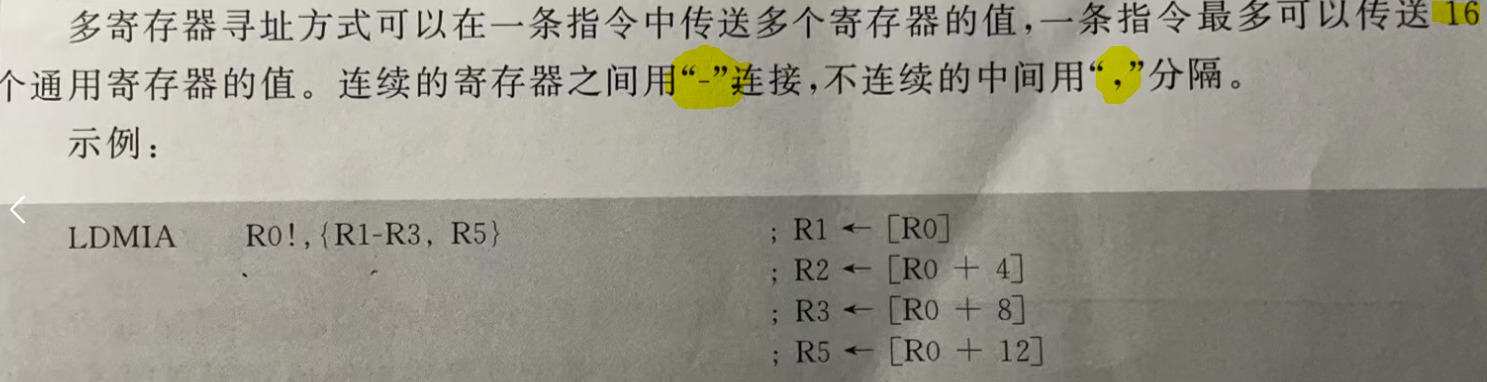
- LDM
LDMIA (Load multi increase after) / LDMIB(Load multi increase before)
LDMIA Rn{!}, reglist / LDMIB Rn{!}, reglist
Note: Rn never be R15(PC register), and ! means the R0 should be increased, no ! no increasement
ref to below screenshot, represent that it would respectively write the content of R0 to R1, R0+4 -> R2, R0+8 ->R3, R0+12 ->R5.
LDMIB R0!, {R1-R3,R5}                   ; R0 + 4 ->R1
                                        ; R0 + 8 ->R2
                                        ; R0 + 12 -> R3
                                        ; R0 + 16 -> R5
Attentive users could be often able to predict how those below cmd to behave:
LDMDA(Load multi decrease after)/LDMDB(Load multi decrease before)
- STM
STMIA(Store multi increase after) / STMIB(Store multi increase before)
STMIA Rn{!}, reglist / STMIB Rn{!}, reglist
Note: Rn never be R15(PC register)
typically, applied to save scenario, data copy.
STMIA  R0!, {R1-R9}                     ; copy the contents of R1~R9 registers into the R0 reg,
                                       ; the pointer addr(the content of R0) should increased after each value copy
                                       ; R1 -> R0
                                       ; R2 -> R0 + 4
                                       ; ...
                                       ; R9 -> R0 + 4*8

STMIB  R1!, {R2-R9}                     ; copy the contents of R2~R9 registers into the R1 reg,
                                       ; the pointer addr(the content of R1) should increased before each value copy
                                       ; R2 -> R1 + 4
                                       ; ...
                                       ; R9 -> R1 + 4*8
Ok well, Definitely like the behavors of STMDA/STMDB Rn! reglist could be predicted too.
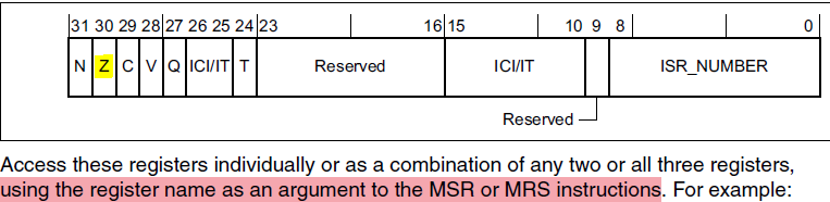
- MRS & MSR
MRS {condition}  Rd, specialReg                       ; (Move from special register to general register)
MSR {condition}  specialReg  Rd                       ; (Move from general register to special register)
Those two cmds are applied in conjunction with each other.
Read-Modify-Write operations on the special registers such as APSR or IPSR etc. register, as well as switching processor mode.
MRS R0, CPSR                          ; Read out the contents of CPSR reg into R0 (R0 = CPSR)
BIC R0, R0, #0x80                     ; BIC(BIT CLEAR) R0 = R0 & ~(0x80)
MSR CPSR, R0                          ; Read out the contents of R0 into CPSR => CPSR &= ~(0x80)
MOV PC, R14                           ; return the scenario
- MOV
MOV <Rd>, <Rn>
MOV R0, R0           ; just like NOP
MOV PC, LR           ; just like BX LR; jump to where to call sub program
                     ; copy the content of R14 to PC Reg
MOV <Rd>, < shift_operand >
MOV R0, R0 ,LSL#3 ; R0 = R0 * 2^3
MOV <Rd>, <immediate number >
Actually the above sub program could be re-writed as following
str_wildcard:

    MOV [R0], #0x55aa                ; write the content(0x55aa) to the content of R0(0x08003800) instead of R0 itself.
- ADD & SUB
ADC <Rd>, <Rm>                                             ; Rd += Rm+C
ADD <Rd>, <Rm>                                             ; Rd += Rm
ADD <Rd>, <Rn>, #<immed_3>                                 ; Rd= Rn+Imm3
ADD <Rd>, #<immed_1>                                       ; Rd += Imm1
ADD <Rd>, <Rn>, <Rm>                                       ; Rd = Rn + Rm
ADD <Rd>, PC, #<immed_2>*4                                 ; Rd = PC + Imm2 *4
SUB <Rd>, #<immed_1>                                       ; Rd-= Imm1
SUB <Rd>, <Rn>, <Rm>                                       ; Rd = Rn - Rm
SUB SP, #<immed_1> * 4                                     ; SP-= Imm1*4
- TST & CMP
TST <Rn>, <Rm> ; Rn & Rm, update Z-Flag
TST R0, #0x10                       ; `Z-Flag` = 1 (if 0x0 == R0 & 0x10),  otherwise `Z-Flag` = 0
BNE LABEL1                           ; Jump to label1 if `Z-Flag` == 0
CMP R0, #0x11                        ; R0 - 0x11, `Z-Flag` = 1 (if R0 == 0x11), otherwise `Z-Flag` = 0
BEQ LABEL2                           ; Jump to label2 if `Z-Flag` == 1
Note: what’s the differences between TST & CMP.
- The TST instruction update the condition flags register by executing a logical AND operation between the value in the
R0register and an operand (here 0x01 in this case). - The CMP instruction update the condition flags register by executing subtraction.
- If the value of the
R0register is equal to the operand, the zero flag (Z) will be set to1. - If the value in the register is
less thanthe operand, the negative flag (N) will be set to1. - If the value in the register is
greater thanthe operand, the carry flag (C) will be set to1
- If the value of the


 783
783

 被折叠的 条评论
为什么被折叠?
被折叠的 条评论
为什么被折叠?
 到【灌水乐园】发言


