


The essential property of a lens is that it bends radiation to focus it.
So, if we were to draw that, here's a lens.
And what that means is that radiation coming to it,
0:26
is focused.
0:32
Now in this case, I've drawn a plane wave, or
illumination that comes to the lens in a plane.
And a lens would focus a plane wave to a particular point,
which is called the focus of the lens.
0:51
Now, an object with that property, and a lens with that same property,
0:58
if the radiation instead were diverging from some source, again,
the lens, the essential property of the lens is that it bends the radiation and
causes it to focus.
Now in this case, because the radiation,
1:18
comes to a diverging, it takes longer after the lens for
that bent radiation to focus to a single point.
But nevertheless, it does come again to a focal point.
And that's the essential property of a lens.
Now let's spend a little bit of time trying to understand how a lens works.
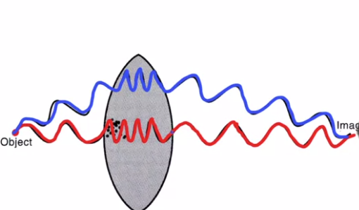
And let's start with an optical lens, or a lens that is used in a light microscope.
And so here in front of us, we have an image of an optical lens.
1:49
And here, we imagine that there's an object, and
as light is scattered off of this object in all directions, it's scattered
in all these different directions, let's consider just two of the directions.
Namely, this direction, and also this direction.
Now the reason we're drawing these as wavy lines instead of like a straight ray,
sometimes we need to think about radiation as a set of rays.
And this will help us when we think about electrons.
An electron, it's natural for us to think of it as a particle that's moving in
a trajectory, and so that's like a ray.
But in order to really understand lenses and refraction and
all the effects that happen, in other cases,
we have to understand radiation as waves.
So think more like waves coming across the ocean,
as wave fronts that travel forward in space.
And as a wave front travels forward in space, the waves have amplitudes and
they have phases.
The amplitude stays the same as it moves forward, but the phase continually
oscillates from 0 to 360 degrees and around and around 0 to 360 degrees.
And so, we can represent the idea that you have an oscillating wave front with
a phase that's oscillating up and down, as it goes through the wavelengths.
We can represent that as a wavy line.
So, the scattering that is moving forward in this direction will represent
as this wavy line to suggest that it's phase is oscillating up and down.
And as it travels through the air, it has a certain wavelength and
it gives it a certain color, obviously.
3:43
But the properties of glass are different than the properties of air.
Namely, glass is more dense.
And one of the ways you can imagine the propagation of radiation
is that as it encounters atoms of a material, it causes
4:01
each atom to be like a scattering center
that scatters radiation in a spherical wave front away from it.
And because the atoms in the glass are much
more densely packed than they are in the air,
4:19
as the wave propagates through the denser media, it slows down.
4:25
Now it has the same energy, but
because the wave front slows down, it has a compressed wavelength.
And so now, as this wave enters the glass,
we'll show it with a compressed wavelength as it passes through the glass.
4:40
And then as it exits the back side of the glass, it's wavelength goes back
to the wavelength in air, and it proceeds on in the forward direction.
Okay, so that's the scattering in this main direction.
Now let's consider another ray, or wave front, that is moving in this direction.
Now it precedes through the air with this characteristic wavelength.
Now when it hits the surface of the glass,
it excites scattering centers within the glass, and
these scattering centers scatter spherical wavelets in all directions.
Well it turns out that in one particular direction, namely,
straight across the glass lens,
5:26
the wavelength will be compressed just like it was in the other case, and
as it passes through this glass lens, it will have a shorter wavelength.
And then when it emerges, again, it scatters in all possible directions.
And it turns out there's one special direction that we need to think about,
which is the one that heads towards the middle again.
And the wavelength expands again to the wavelength in air.
Now what's special about this particular direction is that if you
add up the total number of wavelengths that the ray
6:05
goes through along this path from object to this image position,
if you add up the number of wavelengths that happen here,
there's a lot of extra wavelengths in the glass.
It turns out to be the same number of wavelengths as this ray
6:22
passes through to go in this longer path in the air, and then this shorter
path through the glass here at the top, and then a longer path back in the air, so
that when these two rays reach this point, they're once again in phase.
They've gone through the same number of wavelengths and
their optical path
lengths are equal.
Now, there was scattering
in all directions away from that scattering center,
and they're scattering in all directions away from that scattering center.
And you can imagine that there was scattering in all directions from there,
and all directions in there.
And so we could have considered, well,
what is the interference of all these beams at a point over here, or
a point over here, or maybe over here, or maybe over here.
Well it turns out that there's just one special position on the other side of this
lens where all of the radiation that's scattering away from this object
7:32
will have the same number of wavelengths as it approaches the same point in space.
And because their optical path lengths are the same, they arrive at the image
position with the same phase, and they constructively interfere.
But in all these other positions, the waves destructively interfere.
And so the probability, let's say an object scatters a photon.
And by scattering the photon The wavefront moves forward
in all these possible directions.
It hits the lens.
8:09
And there is a special pathway where if all these rays travel
straight across the lens, and then are bent again, and
head towards this direction, all of these path lengths will be the same, and
it will constructively interfere at this special position.
And so the probability, if we were to put a detector in front of the lens.
If we put a detector right here, like a piece of film,
there's one position on the back side of this lens where
the probability of detecting a photon would be very high, and that's right here.
And everywhere else, the probability would be very low.
8:48
And so this is in essence how optical lenses work.
In addition to just focusing radiation,
lenses introduce the possibility of producing a magnified image.
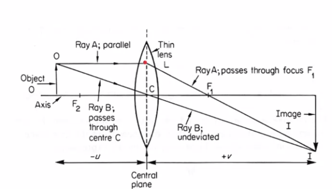
So next, now, let's consider how you would use a lens to produce a magnified image.
And to do that, we'll look at what's called a ray tracing diagram.
And so what we have at the center is we have a lens.
Okay, so here's the optical lens that bends the radiation.
And each lens has what's called an optical axis, the axis right through it.
And so here's the optical axis of that lens.
9:29
And now let's consider an object on that optical axis.
So here's our object.
And let's imagine that light is scattering away from that object
at all different positions along it.
So from the top there's light scattering in all directions,
also from the middle of it there's light scattering in all possible directions,
and also from the base, it's scattering from all possible directions.
So this is all happening simultaneously, but let's simplify and
just consider the light that scatters from the tip of our object.
Okay, so there's light going in all of these directions.
But again to simplify,
let's just consider the light that goes into special directions.
Okay, the first one is one ray of light scattered from the tip
will pass through the center of the lens, right along here.
10:22
And because it passes through the center of the lens,
that ray is unbent, undeviated here, and so
we just draw it straight through on into wherever it goes from there.
Now, the second important ray that we'll follow
is the ray that goes parallel to the optical axis.
Now, when it encounters the lens, it is bent, or refracted,
and remember a lens, each lens has a characteristic focal distance.
And the focal distance is defined as if you have radiation
parallel to the optical axis, so radiation coming in parallel to the optical axis,
it will all be bent to focus at this particular position in the focal point.
So, like all parallel radiation, this ray, when it hits the lens,
is bent so that it'll pass through the focal position, and
if we follow it past that focal position we find that eventually it
encounters this other ray of interest down at this location.
So it turns out that if we consider any of the rays passing through, say,
an intermediate position, it turns out that they will all be bent so
that they all pass through that special position here.
And so the scattering that comes from the tip of this object,
in all these directions, what the lens does is it will focus it all so
that it all re-interferes again down here.
12:00
And so the interference will be in phase right there and
it'll produce a high probability of detecting a photon at this position.
Ant this position is farther away from the optical axis
than the tip of the object was originally.
And that is what we mean by magnification.
Now, it's also true that all of the radiation that scatters off the object,
say here, so
if it was a person that we were imaging, this would be the top of their head.
This would be somewhere around their waist.
Scattering from their waist will also come out in all possible directions and
the lens will focus it to a position not at the tip but
somewhere about halfway down the tip.
But it'll all be focused in a position right about here.
Finally, say all of the scattering that
comes from the persons foot will come out in all directions,
and what the lens will do is it will focus it all into
a spot right along the optical axis right here.
So we say that scattering from the optical axis is focused back onto
the optical axis.
Scattering that occurs halfway up this object is focused to a position
farther down over here, and scattering that comes from the very tip of the object
is all focused to a position even further.
And the distances between these positions
are proportional to the distances between these positions.
In fact, the magnification of this lens system
13:43
turns out to be the ratio of this image distance
from the central plane of the lens out to the position of the image plane,
that's v, divided by the distance between that same
central plane of the lens to the distance to the object, that's u.
And the magnification turns out to be proportional to that ratio.
In other words, the further out this is the more these get spread out and
the higher the magnification.
Another key equation that relates the properties of this system is what's called
the thin lens equation, which is that one over the focal distance of this lens
is equal to 1 over the distance u plus 1 over the distance v,
the image and object distances, respectively.
14:36
So the fact that a lens can focus radiation introduces the possibility
of producing a magnified image on an image plane past the lens.
And now I want you to imagine the first people that once they realized
that an electron could be thought of as a wave in addition to a particle,
the idea emerged that well, could we possibly then make an electron microscope?
Well, the essential thing you need to build an electron microscope
is an electron lens.
15:12
And they might've thought to themselves, how can we build a lens for electrons?
And it turns out it's very simple.
15:22
If you just take a wire and coil it into a circle,
15:28
and then pass a current through it, you may remember from college physics
that the magnetic field that results, the magnetic field lines look like this.
They cover the surface of a toroid, like the surface of a doughnut,
okay, so imagine magnetic field lines like this.
Now, if we have electrons coming from a gun above that, and
if the electrons come straight down through that magnetic field,
they'll be undeflected.
Just like a photon going through the middle of a glass lens.
If on the other hand an electron is coming at an angle to the optical axis,
it will experience forces that bend its path.
16:19
And remember that the force on an electron is equal to the cross
product of its velocity and the magnetic field that it's passing through.
So an electron passing in this direction would have a velocity in this direction.
And the magnetic field lines as it passes through this lens are curved.
And they look approximately like this.
So the cross product of the velocity with the magnetic field
16:49
introduces a force on the electron in this direction that pushes it out.
So the electron starts to be pushed out around the optical axis.
Now as soon as the electron picks up a velocity essentially circumferentially
around the lens, now it's velocity is in this direction.
And the magnetic field lines, again, are this direction.
And the cross product of the velocity and
the magnetic field are a force that pulls the electron towards the optical axis.
17:25
So as the electron comes down, first it gets pushed circumferentially.
And then it gets drawn towards the optical axis as it penetrates.
As it goes down through the bottom of the lens,
opposite forces cause its circumferential movement to stop.
And so it comes out emerging straight down the microscope again.
But both the top and
the bottom of the lens impose a force that draws it to the optical axis.
And that's how an electron lens works.
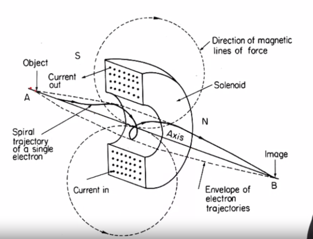
Okay, now let's look at the same thing with the aid of this drawing.
18:10
So what we see here in this drawing is the coil of an electron lens.
And so the wire wraps around and around like this.
Now here, this is the coil cut in cross-section.
So each of the wires looks like a little dot.
But each of the wires goes around and around in a coil, okay?
And then we'll erase that.
And because of the current going around in that coil this
produces electric field lines that follow this trajectory.
Well, they've got the arrow going the other way around.
Electric field lines going like this.
And they go all around the coil.
We're just showing two representative lines.
But remember that it covers it's symmetric around the lens.
And so these cover the surface of what looks like a doughnut.
Now the optical axis of this electron lens is this line here
that goes straight through the middle.
19:17
Okay, and so let's consider electrons that emerge from a point over here.
19:25
And some of the electrons go straight down the middle of the lens along
the optical axis, and they head right to the image plane.
And they're undeflected as they pass through the lens system.
If, on the other hand, we consider an electron that is not following
the optical axis but instead is coming away from the optical axis,
as it enters the magnetic field of the electron lens,
it experience forces that first cause it to be pushed laterally.
And then once it's moving laterally,
to be pulled in towards the optical axis of the lens.
So it follows this spiral trajectory.
And as it passes though the back side of the lens,
the circumferential forces are reversed.
And so as it emerges it no longer is coiling through
around the optical axis anymore.
But the forces that cause it to be pushed towards the optical axis are reinforced.
And so the net influence of the lens magnetic field is to cause something
that was moving away from the optical axis to now
be moving down towards the optical axis.
In other words, this coil of wires creates a magnetic
field that bends radiation that's initially diverging
until it's now converging on the optical access.
And that is a lens.
21:06
Now one of the things to notice about the situation is that
because the electrons follow this coiled path,
it turns out that as an image passes down through an electron microscope,
each time it hits a lens it will rotate within the microscope.
It's as if it was rotating the image.
And that will come up later as an important point.
Okay, so that's how an electron lens works.
And an electron microscope is just a stack
of electron lenses with the filament at the top.
21:43
But it turns out that each lens has a set of components that always go with it.
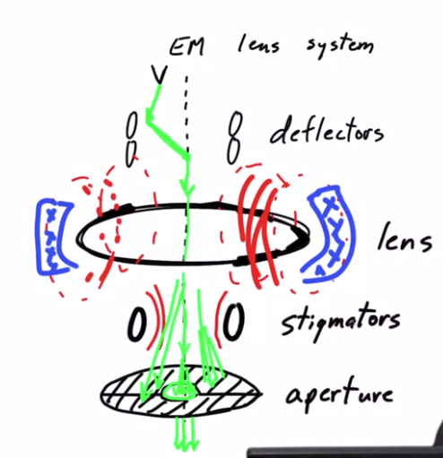
So next we're going to talk about an EM lens system,
which has four components that always go with an EM lens.
Okay, let's start by drawing an EM lens.
A coil of wires that's gonna produce the magnetic field that focuses the radiation.
And above it there's a source of electrons.
Now The EM lens has an optical axis.
And so let's draw the optical axis right down through the middle.
And ideally, the incoming radiation would be exactly on top
of the optical axis so that the radiation would come straight down the optical axis.
Now in fact, in electron microscopes we image distances on the order of angstroms.
And the dimensions are very small.
So it turns out that it's actually impossible to stack the lenses physically
so that each lens is exactly on top of the lens above it.
And because of that,
the incoming radiation isn't exactly along the optical axis.
And so in order to depict that I'm gonna put the filament over here.
Imagine that the filament was over there.
And so the electrons coming out of that filament are coming
in this kind of position.
And this has two problems.
23:24
One is that the radiation coming out of the filament
is not along the optical axis.
The second problem is that the lenses,
23:36
when they're actually physically screwed into the instrument,
could be a little bit off of horizontal with respect to each other.
And the lens fields could be just a little bit off of perfectly vertical.
And we can depict that by exaggerating showing the electron beam coming
down at an angle that's different than the optical axis of the lens.
Now of course, this is highly exaggerated.
But the two problems that every lens system faces Is that the incoming
radiation is neither parallel to the optical axis of that lens,
nor is it coming down coincident with the optical axis,
but instead it's displaced.
And so because of that, each EM lens is equipped with
a pair of deflectors, so these are deflectors.
24:33
And these are coils that are setup perpendicular to
the direction of the electron beam.
And they have the property that they can produce magnetic fields,
that can bend the incoming
24:50
electron beam in any direction necessary.
So if we use the top pair of deflectors, these two deflectors,
to deflect the incoming beam in this particular direction.
We can use the bottom set of deflectors to correct for the bend,
and send the new electron beam directly down the optical axis of the lens,
and so that's the purpose of deflectors.
Now the next problem with any real EM lens,
is that the magnetic field lines that it produces,
remember the electron lens produces these magnetic field
lines that are the cause of the electrons being bent and
being focused towards the optical axis.
But in fact, no EM lens produces
a perfectly symmetrical magnetic field.
So for instance, one of the problems is that as this wire is produced.
26:04
As the wire is bent around the lens, it could be that as that wire
was formed some parts of the wire are a little bit thinner than another part,
or maybe they cooled a little bit differently.
And so the resistivity within the wire is not exactly the same in every location,
and if the resistance is different,
then the current flowing through that is gonna behave a little bit differently,
and the magnetic field that it produces won't be exactly symmetric.
In addition, as this wire is bent around to form the lens,
there may be in certain positions, bends a little bit tighter than somewhere else.
I mean we can exaggerate it and put a little kink here on the corner.
As you bend the wire around, it may not be perfectly circular in all locations and
because of that, the magnetic field lines won't be exactly symmetric.
Finally, there may be in the room where the microscope is, sources of heat.
The lens itself produces quite a bit of heat as the current
passes through the lens.
The lens heats up, and it becomes too hot, and
so in actual electron microscopes,
the lens is surrounded by cooling channels of water.
Where you have water passing through cooling
channels around the lenses to keep it cool.
Well, the water isn't always the same temperature.
And if a person comes into the room, the heat from their body can actually
heat up the electron microscope so it's just a little bit warmer,
say, on one side of the lens than it is on the other side of the lens.
And if that's true, then the resistivity
of the wires change a little bit over here compared to over there.
And all of these factors change subtly, what
the magnetic field lines look like around that lens, and so it's never perfect.
And because of that the lenses are what's called stigmatic.
What stigmatism is, is if the lens is stronger,
say in one area, than another, the electron beam
will be focused more strongly where the magnetic
field is stronger than it may be focused in another
direction, and this is called stigmatism, and
to correct it, each EM lens system has as part of it
28:58
Stigmators.
29:01
And these coils have the property that they can add additional
field strength in one location say, as opposed to another.
In order to compensate for
asymmetries in the main field that's produced by the lens itself.
29:21
And finally, below the stigmators, the fourth element of any EM lens system,
is an aperture, and I'll draw it like a plate within the middle, but actually,
if I were to draw it in 3D It's a washer.
29:38
It's like a washer that blocks all of the radiation
29:47
that's going far from the optical axis of the lens.
Any radiation that's moving far away from the optical axis
will hit the metal of the aperture and be absorbed there.
And so the only radiation that goes through is the radiation within a small
cone here that passes through the hole in the center of the aperture,
and so we'll label that as the aperture.
30:20
And, it turns out that the radiation that's far from the optical axis
won't focus well through the later lenses, and it'll actually cause just
a blurring of the image, and that's due to aberrations in the lenses.
There's a number of aberrations that get worse and
worse with distance away from the optical axis.
And so it turns out to be advantageous to just block all of the scattering that's
far from the optical axis, and that's done with an aperture, and
so let's label the last element.
So all EM lenses have four basic components.
They have deflectors, which move the incoming beam from wherever
it's coming onto the optical axis and straight down the optical axis.
Then there's a lens, that focuses the radiation.
There are stigmators to correct for
imperfections in the shape of the magnetic field that's doing the focusing.
And there's an aperture to limit
the radiation that's passed through
to just the radiation that's going
through near the optical access,
and these are the four components
of a complete EM lens system.


 2301
2301


 被折叠的 条评论
为什么被折叠?
被折叠的 条评论
为什么被折叠?
 到【灌水乐园】发言


