


NSD NETWORK DAY04
- 查看及配置交换机管理地址
1 查看及配置交换机管理地址
1.1 问题
交换机是目前用于组建局域网的主要设备,交换机根据MAC地址表实现数据帧的转发,通过查看MAC地址表更加有利于交换机工作原理的理解;通过查看CISCO设备邻居信息来了解网络拓扑;通过telnet方式远程访问、配置交换机,这种方式要求此交换机已配置有IP地址。
- 查看交换机MAC地址表
- 查看CISCO设备邻居信息
- 交换机地址配置及默认网关
1.2 方案
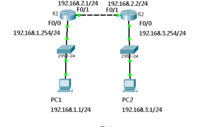
网络拓扑,如图-1所示。
/
图-1
步骤一:查看交换机MAC地址表
1)按拓扑配置PC1及PC2的IP地址并查看,如下所示:
- PC>ipconfig
- FastEthernet0 Connection:(default port)
- Link-local IPv6 Address.........: FE80::2D0:97FF:FED2:2DB0 //PC1的MAC地址
- IP Address......................: 192.168.1.1 //PC1的IP地址
- Subnet Mask.....................: 255.255.255.0
- Default Gateway.................: 0.0.0.0
- PC>ipconfig
- FastEthernet0 Connection:(default port)
- Link-local IPv6 Address.........: FE80::2D0:BCFF:FE56:AB31 //PC2的MAC地址
- IP Address......................: 192.168.1.2 //PC2的IP地址
- Subnet Mask.....................: 255.255.255.0
- Default Gateway.................: 0.0.0.0
2)PC1通过ping命令测试与PC2的连通性:
- PC>ping 192.168.1.2
- Pinging 192.168.1.2 with 32 bytes of data:
- Reply from 192.168.1.2: bytes=32 time=2ms TTL=128
- Reply from 192.168.1.2: bytes=32 time=0ms TTL=128
- Reply from 192.168.1.2: bytes=32 time=3ms TTL=128
- Reply from 192.168.1.2: bytes=32 time=0ms TTL=128
- Ping statistics for 192.168.1.2:
- Packets: Sent = 4, Received = 4, Lost = 0 (0% loss),
- Approximate round trip times in milli-seconds:
- Minimum = 0ms, Maximum = 3ms, Average = 1ms
3)查看交换机MAC地址表:
- Switch#show mac-address-table
- Mac Address Table
- -------------------------------------------
- Vlan Mac Address Type Ports
- ---- ----------- -------- -----
- 1 00d0.97d2.2db0 DYNAMIC Fa0/1
- 1 00d0.bc56.ab31 DYNAMIC Fa0/2
步骤二:查看CISCO设备邻居信息
1)配置路由器接口IP:
- Router>enable
- Router#configure terminal
- Router(config)#interface fastEthernet 0/0
- Router(config-if)#ip address 192.168.1.254 255.255.255.0
- Router(config-if)#no shutdown
2)进入交换机特权模式通过命令查看CISCO设备邻居信息:
- Switch#show cdp neighbors
- Capability Codes: R - Router, T - Trans Bridge, B - Source Route Bridge
- S - Switch, H - Host, I - IGMP, r - Repeater, P - Phone
- Device ID Local Intrfce Holdtme Capability Platform Port ID
- Router Fas 0/3 179 R C2600 Fas 0/0
步骤三:交换机地址配置及默认网关
1)配置IP地址(192.168.1.10/24)
执行“int vlan1”(或interface vlan1)指令进入交换机的vlan1接口配置,再执行“ip add 192.168.1.10 255.255.255.0”配置IP地址(ip add指令相当于ip address),执行“no shutdown”启用此接口,如下所示:
- Switch(config)# int vlan1 //进入vlan1接口
- Switch(config-if)# ip add 192.168.1.10 255.255.255.0 //配置IP地址
- Switch(config-if)# no shutdown //启用接口
- %LINK-5-CHANGED: Interface Vlan1, changed state to up
- %LINEPROTO-5-UPDOWN: Line protocol on Interface Vlan1, changed state to up
2)进入交换机全局配置模式配置交换机默认网关地址:
- Switch#configure terminal
- Switch(config)#ip default-gateway 192.168.1.254
3)确认当前的运行配置
直接执行“end”指令返回特权模式:
- Switch(config-if)# end //返回特权模式
- Switch#
- %SYS-5-CONFIG_I: Configured from console by console
4)确认vlan1接口的IP及网关地址信息:
- Switch#show running-config
- Building configuration...
- Current configuration : 1026 bytes
- !
- version 12.1
- no service timestamps log datetime msec
- no service timestamps debug datetime msec
- no service password-encryption
- !
- hostname Switch
- !
- !
- !
- spanning-tree mode pvst
- !
- interface FastEthernet0/1
- !
- interface FastEthernet0/2
- !
- interface FastEthernet0/3
- !
- interface FastEthernet0/4
- interface FastEthernet0/5
- !
- interface FastEthernet0/6
- !
- interface FastEthernet0/7
- !
- interface FastEthernet0/8
- !
- interface FastEthernet0/9
- !
- interface FastEthernet0/10
- !
- interface FastEthernet0/11
- !
- interface FastEthernet0/12
- !
- interface FastEthernet0/13
- !
- interface FastEthernet0/14
- !
- interface FastEthernet0/15
- !
- interface FastEthernet0/16
- !
- interface FastEthernet0/17
- !
- interface FastEthernet0/18
- !
- interface FastEthernet0/19
- !
- interface FastEthernet0/20
- !
- interface FastEthernet0/21
- !
- interface FastEthernet0/22
- !
- interface FastEthernet0/23
- !
- interface FastEthernet0/24
- !
- interface Vlan1
- ip address 192.168.1.10 255.255.255.0 //IP地址与配置一致
- !
- ip default-gateway 192.168.1.254 //网关地址与配置一致
- !
- !
- !
- !
- line con 0
- !
- line vty 0 4
- login
- line vty 5 15
- login
- !
- !
- end
- Top
- 配置静态路由
1 配置静态路由
1.1 问题
路由器可以将不同网段之间的网络连接到一起,当路由器接收到数据包后要查看数据包中的目标IP,再检查自己的路由表,如果路由表中有和目标IP相匹配的路由条目,路由器才能将数据包按照该路由条目所指定的端口转发出去,实现不同网络之间的通信,那么路由器中的路由表是如何实现的呢?配置了路由器接口IP并为UP状态路由表中自动生成直连路由,对于非直连的路由,需通过静态路由管理员手工添加或通过配置动态路自动学习。
- 配置静态路由
- 配置浮动静态路由
- 配置缺省路由
1.2 方案
网络环境及IP地址规划,如图-1所示。
图-1
本例中的配置练习采用思科模拟器 —— Cisco Packet Tracer 6.0,Route采用2621路由器实现。
1.3 步骤
实现此案例需要按照如下步骤进行。
步骤一:配置静态路由
1)R1上配置接口IP
- R1(config)#interface fastEthernet 0/0
- R1(config-if)#ip address 192.168.1.254 255.255.255.0
- R1(config-if)#no shutdown
- R1(config-if)#exit
- R1(config)#interface fastEthernet 0/1
- R1(config-if)#ip address 192.168.2.1 255.255.255.0
- R1(config-if)#no shutdown
2)R2上配置接口IP
- R2(config)#interface fastEthernet 0/1
- R2(config-if)#ip address 192.168.2.2 255.255.255.0
- R2(config-if)#no shutdown
- R2config-if)#exit
- R2(config)#interface fastEthernet 0/0
- R2(config-if)#ip address 192.168.3.254 255.255.255.0
- R2(config-if)#no shutdown
3)R1上添加静态路由
- R1(config)#ip route 192.168.3.0 255.255.255.0 192.168.2.2
4)R1上查看路由表
- R1#show ip route
- Codes: C - connected, S - static, I - IGRP, R - RIP, M - mobile, B - BGP
- D - EIGRP, EX - EIGRP external, O - OSPF, IA - OSPF inter area
- N1 - OSPF NSSA external type 1, N2 - OSPF NSSA external type 2
- E1 - OSPF external type 1, E2 - OSPF external type 2, E - EGP
- i - IS-IS, L1 - IS-IS level-1, L2 - IS-IS level-2, ia - IS-IS inter area
- * - candidate default, U - per-user static route, o - ODR
- P - periodic downloaded static route
- Gateway of last resort is not set
- C 192.168.1.0/24 is directly connected, FastEthernet0/0
- C 192.168.2.0/24 is directly connected, FastEthernet0/1
- S 192.168.3.0/24 [1/0] via 192.168.2.2 //S表示静态路由
5)R2上添加静态路由
- R2(config)#ip route 192.168.1.0 255.255.255.0 192.168.2.1
6)R2上查看路由条目
- R2#show ip route
- Codes: C - connected, S - static, I - IGRP, R - RIP, M - mobile, B - BGP
- D - EIGRP, EX - EIGRP external, O - OSPF, IA - OSPF inter area
- N1 - OSPF NSSA external type 1, N2 - OSPF NSSA external type 2
- E1 - OSPF external type 1, E2 - OSPF external type 2, E - EGP
- i - IS-IS, L1 - IS-IS level-1, L2 - IS-IS level-2, ia - IS-IS inter area
- * - candidate default, U - per-user static route, o - ODR
- P - periodic downloaded static route
- Gateway of last resort is not set
- S 192.168.1.0/24 [1/0] via 192.168.2.1 //S表示静态路由
- C 192.168.2.0/24 is directly connected, FastEthernet0/1
- C 192.168.3.0/24 is directly connected, FastEthernet0/0
7)配置PC1的IP地址为192.168.1.1,网关为192.168.1.254
8)配置PC2的IP地址为192.168.3.1,网关为192.168.3.254
9)测试网络连通性,PC1 ping 192.168.3.1
- PC>ping 192.168.3.1
- Pinging 192.168.3.1 with 32 bytes of data:
- Reply from 192.168.3.1: bytes=32 time=1ms TTL=126
- Reply from 192.168.3.1: bytes=32 time=11ms TTL=126
- Reply from 192.168.3.1: bytes=32 time=10ms TTL=126
- Reply from 192.168.3.1: bytes=32 time=11ms TTL=126
- Ping statistics for 192.168.3.1:
- Packets: Sent = 4, Received = 4, Lost = 0 (0% loss),
- Approximate round trip times in milli-seconds:
- Minimum = 1ms, Maximum = 11ms, Average = 8ms
步骤二:配置浮动静态路由
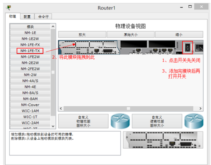
1)在以上静态路由实验的基础上,先分别进入R1与R2的特权模式输入write命令保存配置信息,然后分别进入R1与R2的物理配置界面,点击开关按钮关闭路由器,添加NM-1FE-TX模块并再次点击开关按钮,如下图-2所示。
图-2
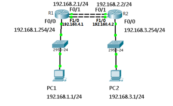
2)添加模块后将R1的F1/0接口连接到R2的F1/0接口修改拓扑如下图-3所示:
图-3
3)配置R1的F1/0接口IP
- R1(config)#interface fastEthernet 1/0
- R1(config-if)#ip address 192.168.4.1 255.255.255.0
- R1(config-if)#no shutdown
4)配置R2的F1/0接口IP
- R2(config)#interface fastEthernet 1/0
- R2(config-if)#ip address 192.168.4.2 255.255.255.0
- R2(config-if)#no shutdown
5)R1上添加静态浮动路由
- R1(config)#ip route 192.168.3.0 255.255.255.0 192.168.4.2 50 //管理距离50
6)R2上添加静态浮动路由
- R2(config)#ip route 192.168.1.0 255.255.255.0 192.168.4.1 50 //管理距离50
7)R1上查看路由表
- R1#show ip route
- Codes: C - connected, S - static, I - IGRP, R - RIP, M - mobile, B - BGP
- D - EIGRP, EX - EIGRP external, O - OSPF, IA - OSPF inter area
- N1 - OSPF NSSA external type 1, N2 - OSPF NSSA external type 2
- E1 - OSPF external type 1, E2 - OSPF external type 2, E - EGP
- i - IS-IS, L1 - IS-IS level-1, L2 - IS-IS level-2, ia - IS-IS inter area
- * - candidate default, U - per-user static route, o - ODR
- P - periodic downloaded static route
- Gateway of last resort is not set
- C 192.168.1.0/24 is directly connected, FastEthernet0/0
- C 192.168.2.0/24 is directly connected, FastEthernet0/1
- S 192.168.3.0/24 [1/0] via 192.168.2.2
- C 192.168.4.0/24 is directly connected, FastEthernet1/0
- R1#show ip rou
- R1#show ip route
- Codes: C - connected, S - static, I - IGRP, R - RIP, M - mobile, B - BGP
- D - EIGRP, EX - EIGRP external, O - OSPF, IA - OSPF inter area
- N1 - OSPF NSSA external type 1, N2 - OSPF NSSA external type 2
- E1 - OSPF external type 1, E2 - OSPF external type 2, E - EGP
- i - IS-IS, L1 - IS-IS level-1, L2 - IS-IS level-2, ia - IS-IS inter area
- * - candidate default, U - per-user static route, o - ODR
- P - periodic downloaded static route
- Gateway of last resort is not set
- C 192.168.1.0/24 is directly connected, FastEthernet0/0
- C 192.168.2.0/24 is directly connected, FastEthernet0/1
- S 192.168.3.0/24 [1/0] via 192.168.2.2 //只有下一跳为192.168.2.2的静态路由
- C 192.168.4.0/24 is directly connected, FastEthernet1/0
8)禁用F/01接口
- R1(config)#interface fastEthernet 0/1
- R1(config-if)#shutdown
9)R1上查看路由表
- C 192.168.1.0/24 is directly connected, FastEthernet0/0
- S 192.168.3.0/24 [50/0] via 192.168.4.2//下一跳接口为192.168.4.2的路由生效
- C 192.168.4.0/24 is directly connected, FastEthernet1/0
10)测试网络连通性,PC1 ping 192.168.3.1
- PC>ping 192.168.3.1
- Pinging 192.168.3.1 with 32 bytes of data:
- Reply from 192.168.3.1: bytes=32 time=0ms TTL=126
- Reply from 192.168.3.1: bytes=32 time=10ms TTL=126
- Reply from 192.168.3.1: bytes=32 time=11ms TTL=126
- Reply from 192.168.3.1: bytes=32 time=1ms TTL=126
- Ping statistics for 192.168.3.1:
- Packets: Sent = 4, Received = 4, Lost = 0 (0% loss),
- Approximate round trip times in milli-seconds:
- Minimum = 0ms, Maximum = 11ms, Average = 5ms
步骤三:配置缺省路由
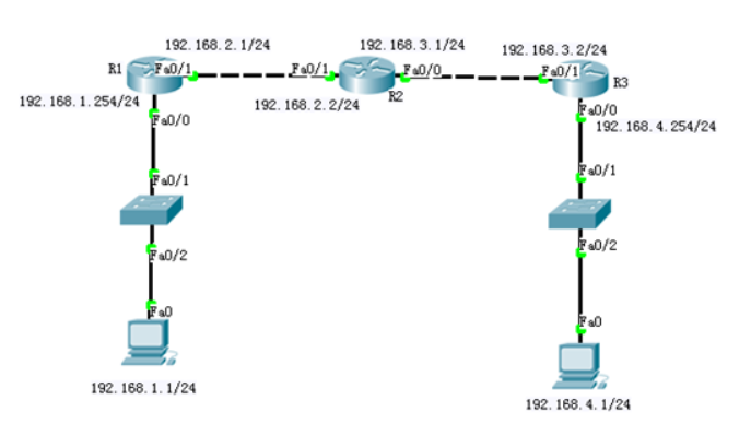
1)网络环境及IP地址规划,如图-4所示
图-4
2)R1上配置接口IP
- Router(config)#interface fastEthernet 0/0
- R1(config-if)#ip address 192.168.1.254 255.255.255.0
- R1(config-if)#no shutdown
- R1(config-if)#exit
- R1(config)#interface fastEthernet 0/1
- R1(config-if)#ip address 192.168.2.1 255.255.255.0
- R1(config-if)#no shutdown
3)R2上配置接口IP
- R2(config)#interface f0/1
- R2(config-if)#ip address 192.168.2.2 255.255.255.0
- R2(config-if)#no shutdown
- R2(config-if)#exit
- R2(config)#interface fastEthernet 0/0
- R2(config-if)#ip address 192.168.3.1 255.255.255.0
- R2(config-if)#no shutdown
4)R3上配置接口IP
- R3(config)#interface fastEthernet 0/1
- R3(config-if)#ip address 192.168.3.2 255.255.255.0
- R3(config-if)#no shutdown
- R3(config-if)#exit
- R3(config)#interface fastEthernet 0/0
- R3(config-if)#ip address 192.168.4.254 255.255.255.0
- R3(config-if)#no shutdown
5)R1、R2、R3上分别添加静态路由
- R1(config)#ip route 192.168.3.0 255.255.255.0 192.168.2.2
- R1(config)#ip route 192.168.4.0 255.255.255.0 192.168.2.2
- R2(config)#ip route 192.168.1.0 255.255.255.0 192.168.2.1
- R2(config)#ip route 192.168.4.0 255.255.255.0 192.168.3.2
- R3(config)#ip route 192.168.1.0 255.255.255.0 192.168.3.1
- R3(config)#ip route 192.168.2.0 255.255.255.0 192.168.3.1
6)R1上查看路由表
- R1#show ip route
- Codes: C - connected, S - static, I - IGRP, R - RIP, M - mobile, B - BGP
- D - EIGRP, EX - EIGRP external, O - OSPF, IA - OSPF inter area
- N1 - OSPF NSSA external type 1, N2 - OSPF NSSA external type 2
- E1 - OSPF external type 1, E2 - OSPF external type 2, E - EGP
- i - IS-IS, L1 - IS-IS level-1, L2 - IS-IS level-2, ia - IS-IS inter area
- * - candidate default, U - per-user static route, o - ODR
- P - periodic downloaded static route
- Gateway of last resort is not set
- C 192.168.1.0/24 is directly connected, FastEthernet0/0
- C 192.168.2.0/24 is directly connected, FastEthernet0/1
- S 192.168.3.0/24 [1/0] via 192.168.2.2 //静态路由
- S 192.168.4.0/24 [1/0] via 192.168.2.2 //静态路由
7)R2上查看路由表
- R2#show ip route
- Codes: C - connected, S - static, I - IGRP, R - RIP, M - mobile, B - BGP
- D - EIGRP, EX - EIGRP external, O - OSPF, IA - OSPF inter area
- N1 - OSPF NSSA external type 1, N2 - OSPF NSSA external type 2
- E1 - OSPF external type 1, E2 - OSPF external type 2, E - EGP
- i - IS-IS, L1 - IS-IS level-1, L2 - IS-IS level-2, ia - IS-IS inter area
- * - candidate default, U - per-user static route, o - ODR
- P - periodic downloaded static route
- Gateway of last resort is not set
- S 192.168.1.0/24 [1/0] via 192.168.2.1 //静态路由
- C 192.168.2.0/24 is directly connected, FastEthernet0/1
- C 192.168.3.0/24 is directly connected, FastEthernet0/0
- S 192.168.4.0/24 [1/0] via 192.168.3.2 //静态路由
8)R3上查看路由表
- R3#show ip route
- Codes: C - connected, S - static, I - IGRP, R - RIP, M - mobile, B - BGP
- D - EIGRP, EX - EIGRP external, O - OSPF, IA - OSPF inter area
- N1 - OSPF NSSA external type 1, N2 - OSPF NSSA external type 2
- E1 - OSPF external type 1, E2 - OSPF external type 2, E - EGP
- i - IS-IS, L1 - IS-IS level-1, L2 - IS-IS level-2, ia - IS-IS inter area
- * - candidate default, U - per-user static route, o - ODR
- P - periodic downloaded static route
- Gateway of last resort is not set
- S 192.168.1.0/24 [1/0] via 192.168.3.1 //静态路由
- S 192.168.2.0/24 [1/0] via 192.168.3.1 //静态路由
- C 192.168.3.0/24 is directly connected, FastEthernet0/1
- C 192.168.4.0/24 is directly connected, FastEthernet0/0
9)按图-4配置PC的IP地址
10)测试网络连通性,PC1 ping 192.168.2.2、192.168.3.1、192.168.3.2、192.168.4.1
- PC>ping 192.168.2.2 //ping 192.168.2.2
- Pinging 192.168.2.2 with 32 bytes of data:
- Reply from 192.168.2.2: bytes=32 time=0ms TTL=254
- Reply from 192.168.2.2: bytes=32 time=0ms TTL=254
- Reply from 192.168.2.2: bytes=32 time=0ms TTL=254
- Reply from 192.168.2.2: bytes=32 time=0ms TTL=254
- Ping statistics for 192.168.2.2:
- Packets: Sent = 4, Received = 4, Lost = 0 (0% loss),
- Approximate round trip times in milli-seconds:
- Minimum = 0ms, Maximum = 0ms, Average = 0ms
- PC>ping 192.168.3.1 //ping 192.168.3.1
- Pinging 192.168.3.1 with 32 bytes of data:
- Reply from 192.168.3.1: bytes=32 time=0ms TTL=254
- Reply from 192.168.3.1: bytes=32 time=3ms TTL=254
- Reply from 192.168.3.1: bytes=32 time=0ms TTL=254
- Reply from 192.168.3.1: bytes=32 time=0ms TTL=254
- Ping statistics for 192.168.3.1:
- Packets: Sent = 4, Received = 4, Lost = 0 (0% loss),
- Approximate round trip times in milli-seconds:
- Minimum = 0ms, Maximum = 3ms, Average = 0ms
- PC>ping 192.168.3.2 //ping 192.168.3.2
- Pinging 192.168.3.2 with 32 bytes of data:
- Reply from 192.168.3.2: bytes=32 time=0ms TTL=253
- Reply from 192.168.3.2: bytes=32 time=12ms TTL=253
- Reply from 192.168.3.2: bytes=32 time=0ms TTL=253
- Reply from 192.168.3.2: bytes=32 time=12ms TTL=253
- Ping statistics for 192.168.3.2:
- Packets: Sent = 4, Received = 4, Lost = 0 (0% loss),
- Approximate round trip times in milli-seconds:
- Minimum = 0ms, Maximum = 12ms, Average = 6ms
- PC>ping 192.168.4.1 //ping 192.168.4.1
- Pinging 192.168.4.1 with 32 bytes of data:
- Reply from 192.168.4.1: bytes=32 time=0ms TTL=125
- Reply from 192.168.4.1: bytes=32 time=10ms TTL=125
- Reply from 192.168.4.1: bytes=32 time=0ms TTL=125
- Reply from 192.168.4.1: bytes=32 time=22ms TTL=125
- Ping statistics for 192.168.4.1:
- Packets: Sent = 4, Received = 4, Lost = 0 (0% loss),
- Approximate round trip times in milli-seconds:
- Minimum = 0ms, Maximum = 22ms, Average = 8ms
11)R1、R3取消静态路由
- R1(config)#no ip route 192.168.3.0 255.255.255.0 192.168.2.2
- R1(config)#no ip route 192.168.4.0 255.255.255.0 192.168.2.2
- R3(config)#no ip route 192.168.1.0 255.255.255.0 192.168.3.1
- R3(config)#no ip route 192.168.2.0 255.255.255.0 192.168.3.1
12)R1、R3添加默认路由
- R1(config)#ip route 0.0.0.0 0.0.0.0 192.168.2.2
- R3(config)#ip route 0.0.0.0 0.0.0.0 192.168.3.1
13)R1上查看路由表
- R1#show ip route
- Codes: C - connected, S - static, I - IGRP, R - RIP, M - mobile, B - BGP
- D - EIGRP, EX - EIGRP external, O - OSPF, IA - OSPF inter area
- N1 - OSPF NSSA external type 1, N2 - OSPF NSSA external type 2
- E1 - OSPF external type 1, E2 - OSPF external type 2, E - EGP
- i - IS-IS, L1 - IS-IS level-1, L2 - IS-IS level-2, ia - IS-IS inter area
- * - candidate default, U - per-user static route, o - ODR
- P - periodic downloaded static route
- Gateway of last resort is 192.168.2.2 to network 0.0.0.0
- C 192.168.1.0/24 is directly connected, FastEthernet0/0
- C 192.168.2.0/24 is directly connected, FastEthernet0/1
- S* 0.0.0.0/0 [1/0] via 192.168.2.2 //默认路由
14)R3上查看路由表
- R3#show ip route
- Codes: C - connected, S - static, I - IGRP, R - RIP, M - mobile, B - BGP
- D - EIGRP, EX - EIGRP external, O - OSPF, IA - OSPF inter area
- N1 - OSPF NSSA external type 1, N2 - OSPF NSSA external type 2
- E1 - OSPF external type 1, E2 - OSPF external type 2, E - EGP
- i - IS-IS, L1 - IS-IS level-1, L2 - IS-IS level-2, ia - IS-IS inter area
- * - candidate default, U - per-user static route, o - ODR
- P - periodic downloaded static route
- Gateway of last resort is 192.168.3.1 to network 0.0.0.0
- C 192.168.3.0/24 is directly connected, FastEthernet0/1
- C 192.168.4.0/24 is directly connected, FastEthernet0/0
- S* 0.0.0.0/0 [1/0] via 192.168.3.1 //默认路由
15)测试网络连通性,PC1 ping 192.168.4.1
- PC>ping 192.168.4.1
- Pinging 192.168.4.1 with 32 bytes of data:
- Reply from 192.168.4.1: bytes=32 time=1ms TTL=125
- Reply from 192.168.4.1: bytes=32 time=0ms TTL=125
- Reply from 192.168.4.1: bytes=32 time=14ms TTL=125
- Reply from 192.168.4.1: bytes=32 time=14ms TTL=125
- Ping statistics for 192.168.4.1:
- Packets: Sent = 4, Received = 4, Lost = 0 (0% loss),
- Approximate round trip times in milli-seconds:
- Minimum = 0ms, Maximum = 14ms, Average = 7ms
1 telnet远程管理
1.1 问题
在企业中为方便网络管理员对Cisco设备的配置,一般需事先在Cisco交换机及路由器上开启远程管理的服务,借助网络通过telnet方式远程访问。
1.2 方案
网络管理员通过telnet方式远程管理S1、R1、S2,网络拓扑如图-1所示。
图-1

本例中的配置练习采用思科模拟器 —— Cisco Packet Tracer 6.0来实现。
1.3 步骤
实现此案例需要按照如下步骤进行。
步骤一:Telnet远程访问思科交换机、路由器
1)配置交换机S1的管理IP
- S1(config)#interface vlan 1
- S1(config-if)#ip address 192.168.1.2 255.255.255.0 //交换机管理IP
- S1(config-if)#no shutdown
2)开启S1的telnet远程管理服务
- S1(config)#line vty 0 4
- S1(config-line)#password 123 //远程管理的密码
- S1(config-line)#login
3)配置用户模式进入特权模式的密码(明文或密文之一)
- S1(config)#enable password 456
4)按图-1所示的IP配置PC1的IP地址,PC1通过telnet方式远程管理S1
- PC>telnet 192.168.1.2
- Trying 192.168.1.2 ...Open
- User Access Verification
- Password: //输入远程管理密码123
- S1>en
- S1>enable
- Password: //输入用户模式进入特模式密码456
- S1# //通过telnet方式登录到S1的特权模式
步骤二:PC1远程管理R1
1)配置路由器R1的接口IP
- R1(config)#interface fastEthernet 0/0
- R1(config-if)#ip address 192.168.1.254 255.255.255.0
- R1(config-if)#no shutdown
- R1(config-if)#exit
- R1(config)#interface fastEthernet 0/1
- R1(config-if)#ip address 192.168.2.254 255.255.255.0
- R1(config-if)#no shutdown
2)开启R1的telnet远程管理服务
- R1(config)#line vty 0 4
- R1(config-line)#password 123 //远程管理的密码
- R1(config-line)#login
3)配置用户模式进入特权模式的密码(明文或密文之一)
- R1(config)#enable password 456
4)PC1通过telnet方式远程管理R1
- PC>telnet 192.168.1.254
- Trying 192.168.1.254 ...Open
- User Access Verification
- Password: //输入远程管理密码123
- R1>en
- R1>enable
- Password: //输入用户进入特模式密码456
- R1# //通过telnet方式登录到R1的特权模式
步骤三:PC1远程管理S2
1)配置交换机S2的管理IP
- S2(config)#interface vlan 1
- S2(config-if)#ip address 192.168.2.2 255.255.255.0 //交换机管理IP
- S2(config-if)#no shutdown
- S2(config-if)#exit
- S2(config)#ip default-gateway 192.168.2.254 //不同网段主机远程管理需给交换机配置网关地址
2)开启S2的telnet远程管理服务
- S2(config)#line vty 0 4
- S2(config-line)#password 123 //远程管理的密码
- S2(config-line)#login
3)配置用户模式进入特权模式的密码(明文或密文之一)
- S2(config)#enable password 456
4)PC1通过telnet方式远程管理S2
- PC>telnet 192.168.2.2
- Trying 192.168.2.2 ...Open
- User Access Verification
- Password: //输入远程管理密码123
- S2>en
- S2>enable
- Password: //输入用户模式进入特模式密码456
- S2# //通过telnet方式登录到S2的特权模式
1 Vlan与trunk配置
1.1 问题
VLAN(虚拟局域网)是对连接到的第二层交换机端口的网络用户的逻辑分段,不受网络用户的物理位置限制而根据用户需求进行网络分段。一个VLAN可以在一个交换机或者跨交换机实现。VLAN可以根据网络用户的位置、作用、部门或者根据网络用户所使用的应用程序和协议来进行分组。基于交换机的虚拟局域网能够为局域网解决冲突域、广播域、带宽问题。
1)按企业部门规划vlan
2)配置交换机之间的链路为中继链路
1.2 方案
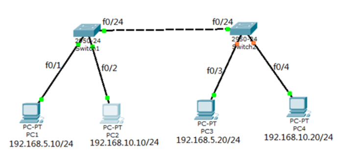
企业网络的拓扑如图-1所示:
图-1
1.3 步骤
实现此案例需要按照如下步骤进行。
步骤一:将两台交换机所连的f0/24端口设置为中继模式
为了使得不同交换机上相同的VLAN可以通信,需要交换机间的链路可以承载所有VLAN数据。Trunk链路不属于任何VLAN,但是可以承载所有VLAN通信。
- tarena-sw1(config)#interface fastEthernet 0/24
- tarena-sw1(config-if)#switchport mode trunk
- tarena-sw1(config-if)#
- tarena-sw2(config)#interface fastEthernet 0/24
- tarena-sw2(config-if)#switchport mode trunk
- tarena-sw2(config-if)#
步骤二:分别在tarena-sw1和tarena-sw2上创建人事部VLAN5和销售部VLAN10
- tarena-sw1(config)#vlan 5
- tarena-sw1(config-vlan)#name HR
- tarena-sw1(config-vlan)#exit
- tarena-sw1(config)#vlan 10
- tarena-sw1(config-vlan)#name Sales
- tarena-sw1(config-vlan)#exit
- tarena-sw1(config)#
- tarena-sw2(config)#vlan 5
- tarena-sw2(config-vlan)#name HR
- tarena-sw2(config-vlan)#exit
- tarena-sw2(config)#vlan 10
- tarena-sw2(config-vlan)#name Sales
- tarena-sw2(config-vlan)#exit
- tarena-sw2(config)#
步骤三:将PC1所连的tarena-sw1的f0/1端口和PC3所连的tarena-sw2的f0/3加入到人事部VLAN5;将PC2所连的tarena-sw1的f0/2端口和PC4所连的tarena-sw2的f0/4加入到销售部VLAN10
把交换机端口加入到VLAN时,也可以不指定switchport mode access,但是有些交换机的端口默认是企望或自动状态。如果该端口所连用户通过软件协商成中继状态,那么他就可以向任何VLAN发送数据,对安全产生威胁。因此,强烈建议设置switchport mode access语句。
- tarena-sw1(config)#interface fastEthernet 0/1
- tarena-sw1(config-if)#switchport mode access
- tarena-sw1(config-if)#switchport access vlan 5
- tarena-sw1(config-if)#exit
- tarena-sw1(config)#interface fastEthernet 0/2
- tarena-sw1(config-if)#switchport mode access
- tarena-sw1(config-if)#switchport access vlan 10
- tarena-sw1(config-if)#exit
- tarena-sw1(config)#
- tarena-sw2(config)#interface fastEthernet 0/3
- tarena-sw1(config-if)#switchport mode access
- tarena-sw2(config-if)#switchport access vlan 5
- tarena-sw2(config-if)#exit
- tarena-sw2(config)#interface fastEthernet 0/4
- tarena-sw1(config-if)#switchport mode access
- tarena-sw2(config-if)#switchport access vlan 10
- tarena-sw2(config-if)#exit
- tarena-sw2(config)#
步骤四:分别在两台交换机上验证VLAN配置结果
交换机所有端口默认都属于VLAN1,VLAN1是交换机预设VLAN,它还有一些特殊应用,不能被删除。
- tarena-sw1#show vlan brief
- VLAN Name Status Ports
- ---- -------------------------------- --------- ---------------------
- 1 default active Fa0/3, Fa0/4, Fa0/5, Fa0/6
- Fa0/7, Fa0/8, Fa0/9, Fa0/10
- Fa0/11, Fa0/12, Fa0/13, Fa0/14
- Fa0/15, Fa0/16, Fa0/17, Fa0/18
- Fa0/19, Fa0/20, Fa0/21, Fa0/22
- Fa0/23
- 5 HR active Fa0/1
- 10 Sales active Fa0/2
- 1002 fddi-default active
- 1003 token-ring-default active
- 1004 fddinet-default active
- 1005 trnet-default active
- tarena-sw1#
- tarena-sw2#show vlan brief
- VLAN Name Status Ports
- ---- -------------------------------- ---------------------------------
- 1 default active Fa0/1, Fa0/2, Fa0/5, Fa0/6
- Fa0/7, Fa0/8, Fa0/9, Fa0/10
- Fa0/11, Fa0/12, Fa0/13, Fa0/14
- Fa0/15, Fa0/16, Fa0/17, Fa0/18
- Fa0/19, Fa0/20, Fa0/21, Fa0/22
- Fa0/23
- 5 HR active Fa0/3
- 10 Sales active Fa0/4
- 1002 fddi-default active
- 1003 token-ring-default active
- 1004 fddinet-default active
- 1005 trnet-default active
- tarena-sw2#
结果显示已经将端口加入到相应VLAN中
步骤五:查看交换机的中继端口状态:
注意端口的Administrative Mode和Operational Mode,管理模式Administrative Mode是指该端口配置模式,而操作模式Operational Mode才是真正生效的模式。比如端口的管理模式Administrative Mode有可能是动态企望dynamic desireble模式,但操作模式Operational Mode是中继trunk。
- tarena-sw1#show interfaces fastEthernet 0/24 switchport
- Name: Fa0/24
- Switchport: Enabled
- Administrative Mode: trunk
- Operational Mode: trunk
- Administrative Trunking Encapsulation: dot1q
- Operational Trunking Encapsulation: dot1q
- Negotiation of Trunking: On
- Access Mode VLAN: 1 (default)
- Trunking Native Mode VLAN: 1 (default)
- Voice VLAN: none
- Administrative private-vlan host-association: none
- Administrative private-vlan mapping: none
- Administrative private-vlan trunk native VLAN: none
- Administrative private-vlan trunk encapsulation: dot1q
- Administrative private-vlan trunk normal VLANs: none
- Administrative private-vlan trunk private VLANs: none
- Operational private-vlan: none
- Trunking VLANs Enabled: ALL
- Pruning VLANs Enabled: 2-1001
- Capture Mode Disabled
- Capture VLANs Allowed: ALL
- Protected: false
- Appliance trust: none
- tarena-sw1#
结果显示tarena-sw1的f0/24端口当前为中继链路,采用了802.1q的封装
步骤六:从PC1[192.168.5.10/24]测试到PC3[192.168.5.20/24]的连通性
- PC>ping 192.168.5.20
- Pinging 192.168.5.20 with 32 bytes of data:
- Reply from 192.168.5.20: bytes=32 time=27ms TTL=128
- Reply from 192.168.5.20: bytes=32 time=22ms TTL=128
- Reply from 192.168.5.20: bytes=32 time=22ms TTL=128
- Reply from 192.168.5.20: bytes=32 time=5ms TTL=128
- Ping statistics for 192.168.5.20:
- Packets: Sent = 4, Received = 4, Lost = 0 (0% loss),
- Approximate round trip times in milli-seconds:
- Minimum = 5ms, Maximum = 27ms, Average = 19ms
- PC>
结果表明两台处于相同VLAN的PC可以互通。不同VLAN的主机,即使IP地址在相同网络也不能通信。如果想实现VLAN间的互通,需要用到后面的“VLAN间路由”知识。
步骤七:从PC2[192.168.10.10]测试到PC4[192.168.10.20]的连通性
- PC>ping 192.168.10.20
- Pinging 192.168.10.20 with 32 bytes of data:
- Reply from 192.168.10.20: bytes=32 time=25ms TTL=128
- Reply from 192.168.10.20: bytes=32 time=11ms TTL=128
- Reply from 192.168.10.20: bytes=32 time=13ms TTL=128
- Reply from 192.168.10.20: bytes=32 time=12ms TTL=128
- Ping statistics for 192.168.10.20:
- Packets: Sent = 4, Received = 4, Lost = 0 (0% loss),
- Approximate round trip times in milli-seconds:
- Minimum = 11ms, Maximum = 25ms, Average = 15ms
- PC>
结果表明两台处于相同VLAN的PC可以互通
2 以太通道配置
2.1 问题
企业需要增加带宽和网络可用性,以太通道可以同时满足这两个条件,而又无需购买新设备。
用练习一,通过调整FTP服务端配置,实现以下目标:
2.2 方案
在某些环境下,为了在现有条件下增加带宽而不增加额外的设备,以太通道是可用技术之一。以太通道为交换机提供了端口捆绑的技术,允许两个交换机之间通过两个或多个端口并行连接,同时传输数据,以提供更高的带宽。
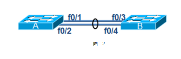
企业网络模拟拓扑环境如图-2所示:
图-2
2.3 步骤
实现此案例需要按照如下步骤进行。
步骤一:在交换机A上分别配置以太通道
太通道的配置模式与Trunk类似,也有开启、企望等。同样的,在生产环境下都是强制设置以太通道处于on的状态,而不是让它们自动协商。
- tarena-sw1(config)# interface range fastEthernet 0/1 – 2
- tarena-sw1(config-if-range)#channel-group 1 mode on
- tarena-sw1(config-if-range)#
步骤二:在交换机B上分别配置以太通道
- tarena-sw2(config)# interface range fastEthernet 0/3 – 4
- tarena-sw2(config-if-range)#channel-group 1 mode on
- tarena-sw2(config-if-range)#
步骤三:在交换机A上查看以太通通道配置
- tarena-sw1# show etherchannel 1 summary
- Flags: D - down P - in port-channel
- I - stand-alone s - suspended
- H - Hot-standby (LACP only)
- R - Layer3 S - Layer2
- U - in use f - failed to allocate aggregator
- u - unsuitable for bundling
- w - waiting to be aggregated
- d - default port
- Number of channel-groups in use: 1
- Number of aggregators: 1
- Group Port-channel Protocol Ports
- ------+-------------+-----------+---------------------------------
- 1 Po1(SU) - Fa0/1(P) Fa0/2(P)
根据输出最后一行小括号中的提示,可以获知以太通道是二层的(S)、正在被使用的(U),端口Fa0/1和Fa02在以太通道中(P)。
步骤四:创建以太通道后,系统会增加一个名称为Port-channel 1的端口,可以通过show running-config命令查看到其信息
- tarena-sw2#show running-config
- Building configuration...
- Current configuration : 1308 bytes
- !
- version 12.2
- no service timestamps log datetime msec
- no service timestamps debug datetime msec
- no service password-encryption
- !
- hostname tarena-sw2
- !
- !
- .. ..
- interface Port-channel 1 //以太通道信息
- switchport mode trunk
- !
- .. ..
3 DHCP服务配置
3.1 问题
大型企业网络客户机数量较多,客记机IP地址配置如果都为静态配置存在如下问题:
1)增加网络管理员工作量
2)静态手动配置容易输入错误
3)静态手动配置容易冲突
3.2 方案
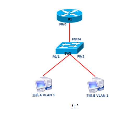
在路由器上配置DHCP服务为客户端自动分配IP地址如图-3所示:
图-3
-
- VLAN 1:192.168.1.0/24
- 网关192.168.1.244
- 首选DNS为202.106.0.20
- 预留IP地址打印服务器:192.168.1.1
- 预留IP地址文件服务器:192.168.1.10
3.3 步骤
实现此案例需要按照如下步骤进行。
步骤一:路由器R1配置DHCP服务
1)配置路由器接口IP
- R1(config)#interface fastEthernet 0/0
- R1(config-if)#ip address 192.168.1.254 255.255.255.0
- R1(config-if)#no shutdown
2)DHCP服务配置
- R1(config)#ip dhcp pool vlan1
- R1(dhcp-config)#network 192.168.1.0 255.255.255.0
- R1(dhcp-config)#default-router 192.168.1.254
- R1(dhcp-config)#dns-server 202.106.0.20
- R1(config)#ip dhcp excluded-address 192.168.1.1
- R1(config)#ip dhcp excluded-address 192.168.1.100
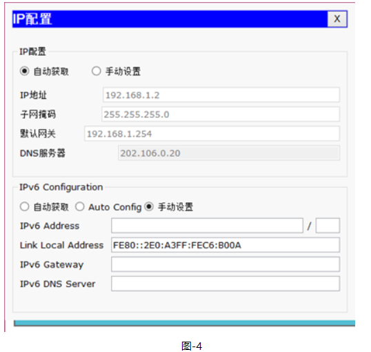
3)设置主机A的IP配置为自动获取如图-4所示:
图-4


 2691
2691


 被折叠的 条评论
为什么被折叠?
被折叠的 条评论
为什么被折叠?
 到【灌水乐园】发言


