


中斷副程式的宣告
__interrupt void adc_isr(void);
宣告全域變量
float ADCV1[10];       //自己增加
float ADCV2[10];       //自己增加
float Voltage1[10];    //uint改為float
float Voltage2[10];    //uint改為float
進入Main後,先系統初始化
InitSysCtrl();
進入該程式後
void
InitSysCtrl(void)
{

    DisableDog();        //Disable看門狗計數器
    InitPll(DSP28_PLLCR,DSP28_DIVSEL);     //初始SYSCLKOUT??
    InitPeripheralClocks();
}
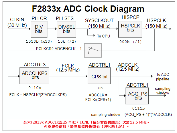
Set HSPCLK Freq=25MHz
   EALLOW;
   #if (CPU_FRQ_150MHZ)     // Default - 150 MHz SYSCLKOUT
     #define ADC_MODCLK 0x3 // HSPCLK = SYSCLKOUT/2*ADC_MODCLK2 = 150/(2*3)   = 25.0 MHz
   #endif
   #if (CPU_FRQ_100MHZ)
     #define ADC_MODCLK 0x2 // HSPCLK = SYSCLKOUT/2*ADC_MODCLK2 = 100/(2*2)   = 25.0 MHz
   #endif
   EDIS;


// Define ADCCLK clock frequency ( less than or equal to 25 MHz )
   // Assuming InitSysCtrl() has set SYSCLKOUT to 150 MHz
   EALLOW;
   SysCtrlRegs.HISPCP.all = ADC_MODCLK;        //ADC_MODCLK=3
   EDIS;
Disable CPU interrupts
DINT;
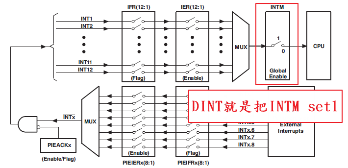
初始PIE控制、Disable CPU interrupts and clear all CPU interrupt flags
- 初始化PIE向量表
   DINT;


   InitPieCtrl();

   IER = 0x0000;
   IFR = 0x0000;

   InitPieVectTable();
可參閱DSP_CPU_Example_2833x_CpuTimer
將中斷向量表指向ADC中斷副程式
// Interrupts that are used in this example are re-mapped to
// ISR functions found within this file.
   EALLOW;  // This is needed to write to EALLOW protected register
   PieVectTable.ADCINT = &adc_isr;
   EDIS;    // This is needed to disable write to EALLOW protected registers
中斷向量表屬於ADCINT1的部分,連結到adc_isr
也就是等一下會設定我們用ADCINT1,去做一個類比轉數位中斷
中斷一旦發生即進入中段副程式
(即當有ADC轉換時就會觸發這個中斷,我們即可在中斷副程式中去做一些我們要做的事情)
ADC中斷副程式 void adc_isr(void)
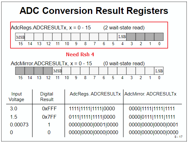
__interrupt void  adc_isr(void)
{
   ADCV1[ConversionCount] = AdcRegs.ADCRESULT0 >>4;
   ADCV2[ConversionCount] = AdcRegs.ADCRESULT1 >>4;

   Voltage1[ConversionCount] = ((float)ADCV1[ConversionCount]/4095)*3.0;  //自己修改
   Voltage2[ConversionCount] = ((float)ADCV2[ConversionCount]/4095)*3.0;  //自己修改


  // If 40 conversions have been logged, start over   如果記錄了40次轉換,請重新開始
  if(ConversionCount == 9)
  {
     ConversionCount = 0;
  }
  else
  {
      ConversionCount++;
  }

  // Reinitialize for next ADC sequence
  AdcRegs.ADCTRL2.bit.RST_SEQ1 = 1;         // Reset SEQ1   將SEQ1的狀態機重置為其初始狀態。這意味著下一個觸發器將開始對CONV00中定義的通道進行新的轉換
  AdcRegs.ADCST.bit.INT_SEQ1_CLR = 1;       // Clear INT SEQ1 bit   向該位寫入1將清除SEQ1中斷標誌位INT_SEQ1。該位不影響EOS_BUF1位。
  PieCtrlRegs.PIEACK.all = PIEACK_GROUP1;   // Acknowledge interrupt to PIE   把PIEACK清除,才能接受其他周邊中斷

  return;
}
初始ADC
InitAdc();
進入該程式
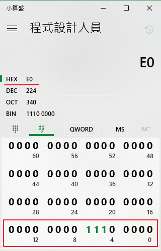
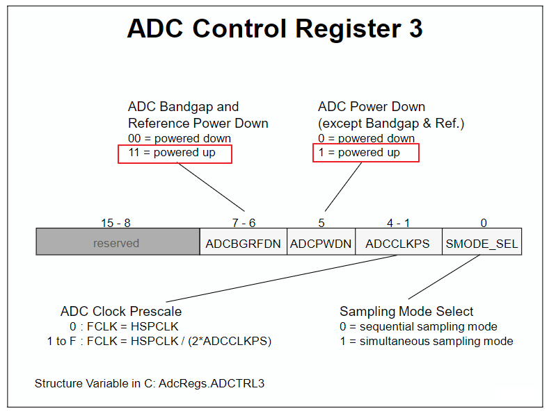
InitAdc(void)
{
    extern void DSP28x_usDelay(Uint32 Count);


    EALLOW;
    SysCtrlRegs.PCLKCR0.bit.ADCENCLK = 1;    //ADC時脈啟動
    ADC_cal();
    EDIS;


    //
    AdcRegs.ADCTRL3.all = 0x00E0;  // Power up bandgap/reference/ADC circuits
    DELAY_US(ADC_usDELAY);         // Delay before converting ADC channels
}
User specific code, enable interrupts:
// Enable ADCINT in PIE
   PieCtrlRegs.PIEIER1.bit.INTx6 = 1;
   IER |= M_INT1; // Enable CPU Interrupt 1
   EINT;          // Enable Global interrupt INTM
   ERTM;          // Enable Global realtime interrupt DBGM

   LoopCount = 0;
   ConversionCount = 0;
Configure ADC
// Configure ADC
   AdcRegs.ADCMAXCONV.all = 0x0001;       // Setup 2 conv's on SEQ1    兩次轉換
   AdcRegs.ADCCHSELSEQ1.bit.CONV00 = 0x3; // Setup ADCINA3 as 1st SEQ1 conv.
   AdcRegs.ADCCHSELSEQ1.bit.CONV01 = 0x2; // Setup ADCINA2 as 2nd SEQ1 conv.
   AdcRegs.ADCTRL2.bit.EPWM_SOCA_SEQ1 = 1;// Enable SOCA from ePWM to start SEQ1   位8(“ePWM_SOCA_SEQ1”)是允許ePWM信號作為“SOCA”用作轉換觸發器的Mask bit。
   AdcRegs.ADCTRL2.bit.INT_ENA_SEQ1 = 1;  // Enable SEQ1 interrupt (every EOS)
Set 2 conv's
ADCINA3 -> ADCRESULT0
ADCINA2 -> ADCRESULT1
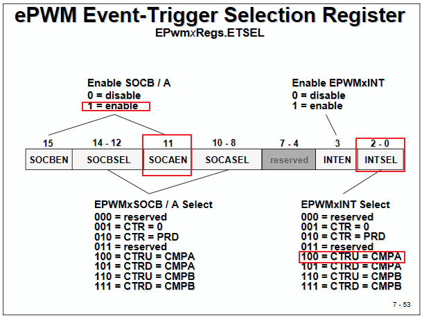
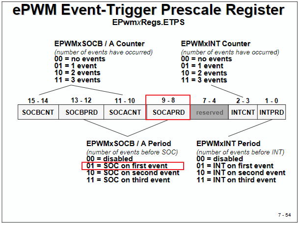
// Assumes ePWM1 clock is already enabled in InitSysCtrl();
   EPwm1Regs.ETSEL.bit.SOCAEN = 1;        // Enable SOC on A group
   EPwm1Regs.ETSEL.bit.SOCASEL = 4;       // Select SOC from from CPMA on upcount
   EPwm1Regs.ETPS.bit.SOCAPRD = 1;        // Generate pulse on 1st event
   EPwm1Regs.CMPA.half.CMPA = 0x0080;      // Set compare A value
   EPwm1Regs.TBPRD = 0xFFFF;              // Set period for ePWM1
   EPwm1Regs.TBCTL.bit.CTRMODE = 0;          // count up and start   上數計時器
ALL Code
//###########################################################################
// Description
//! \addtogroup f2833x_example_list
//! <h1> ADC Start of Conversion (adc_soc)</h1>
//!
//! This ADC example uses ePWM1 to generate a periodic ADC SOC on SEQ1.
//! Two channels are converted, ADCINA3 and ADCINA2.
//!
//! \b Watch \b Variables \n
//! - Voltage1[10]    - Last 10 ADCRESULT0 values
//! - Voltage2[10]    - Last 10 ADCRESULT1 values
//! - ConversionCount    - Current result number 0-9
//! - LoopCount        - Idle loop counter
//
//
//###########################################################################
// $TI Release: F2833x/F2823x Header Files and Peripheral Examples V142 $
// $Release Date: November  1, 2016 $
// $Copyright: Copyright (C) 2007-2016 Texas Instruments Incorporated -
//             http://www.ti.com/ ALL RIGHTS RESERVED $
//###########################################################################

#include "DSP28x_Project.h"     // Device Headerfile and Examples Include File

// Prototype statements for functions found within this file.
__interrupt void adc_isr(void);

// Global variables used in this example:
Uint16 LoopCount;
Uint16 ConversionCount;
float ADCV1[10];
float ADCV2[10];
float Voltage1[10];
float Voltage2[10];

main()
{
// Step 1. Initialize System Control:
// PLL, WatchDog, enable Peripheral Clocks
// This example function is found in the DSP2833x_SysCtrl.c file.
   InitSysCtrl();

   EALLOW;
   #if (CPU_FRQ_150MHZ)     // Default - 150 MHz SYSCLKOUT
     #define ADC_MODCLK 0x3 // HSPCLK = SYSCLKOUT/2*ADC_MODCLK2 = 150/(2*3)   = 25.0 MHz
   #endif
   #if (CPU_FRQ_100MHZ)
     #define ADC_MODCLK 0x2 // HSPCLK = SYSCLKOUT/2*ADC_MODCLK2 = 100/(2*2)   = 25.0 MHz
   #endif
   EDIS;

   // Define ADCCLK clock frequency ( less than or equal to 25 MHz )
   // Assuming InitSysCtrl() has set SYSCLKOUT to 150 MHz
   EALLOW;
   SysCtrlRegs.HISPCP.all = ADC_MODCLK;
   EDIS;

// Step 2. Initialize GPIO:
// This example function is found in the DSP2833x_Gpio.c file and
// illustrates how to set the GPIO to it's default state.
// InitGpio();  // Skipped for this example

// Step 3. Clear all interrupts and initialize PIE vector table:
// Disable CPU interrupts
   DINT;

// Initialize the PIE control registers to their default state.
// The default state is all PIE interrupts disabled and flags
// are cleared.
// This function is found in the DSP2833x_PieCtrl.c file.
   InitPieCtrl();

// Disable CPU interrupts and clear all CPU interrupt flags:
   IER = 0x0000;
   IFR = 0x0000;

// Initialize the PIE vector table with pointers to the shell Interrupt
// Service Routines (ISR).
// This will populate the entire table, even if the interrupt
// is not used in this example.  This is useful for debug purposes.
// The shell ISR routines are found in DSP2833x_DefaultIsr.c.
// This function is found in DSP2833x_PieVect.c.
   InitPieVectTable();

// Interrupts that are used in this example are re-mapped to
// ISR functions found within this file.
   EALLOW;  // This is needed to write to EALLOW protected register
   PieVectTable.ADCINT = &adc_isr;
   EDIS;    // This is needed to disable write to EALLOW protected registers

// Step 4. Initialize all the Device Peripherals:
// This function is found in DSP2833x_InitPeripherals.c
// InitPeripherals(); // Not required for this example
   InitAdc();  // For this example, init the ADC

// Step 5. User specific code, enable interrupts:

// Enable ADCINT in PIE
   PieCtrlRegs.PIEIER1.bit.INTx6 = 1;
   IER |= M_INT1; // Enable CPU Interrupt 1
   EINT;          // Enable Global interrupt INTM
   ERTM;          // Enable Global realtime interrupt DBGM

   LoopCount = 0;
   ConversionCount = 0;

// Configure ADC
   AdcRegs.ADCMAXCONV.all = 0x0001;       // Setup 2 conv's on SEQ1
   AdcRegs.ADCCHSELSEQ1.bit.CONV00 = 0x3; // Setup ADCINA3 as 1st SEQ1 conv.
   AdcRegs.ADCCHSELSEQ1.bit.CONV01 = 0x2; // Setup ADCINA2 as 2nd SEQ1 conv.
   AdcRegs.ADCTRL2.bit.EPWM_SOCA_SEQ1 = 1;// Enable SOCA from ePWM to start SEQ1
   AdcRegs.ADCTRL2.bit.INT_ENA_SEQ1 = 1;  // Enable SEQ1 interrupt (every EOS)

// Assumes ePWM1 clock is already enabled in InitSysCtrl();
   EPwm1Regs.ETSEL.bit.SOCAEN = 1;        // Enable SOC on A group
   EPwm1Regs.ETSEL.bit.SOCASEL = 4;       // Select SOC from from CPMA on upcount
   EPwm1Regs.ETPS.bit.SOCAPRD = 1;        // Generate pulse on 1st event
   EPwm1Regs.CMPA.half.CMPA = 0x0080;      // Set compare A value
   EPwm1Regs.TBPRD = 0xFFFF;              // Set period for ePWM1
   EPwm1Regs.TBCTL.bit.CTRMODE = 0;          // count up and start

// Wait for ADC interrupt
   for(;;)
   {
      LoopCount++;
   }
}

__interrupt void  adc_isr(void)
{
  ADCV1[ConversionCount] = AdcRegs.ADCRESULT0 >>4;
  ADCV2[ConversionCount] = AdcRegs.ADCRESULT1 >>4;

  Voltage1[ConversionCount] = ((float)ADCV1[ConversionCount]/4096)*3.0;
  Voltage2[ConversionCount] = ((float)ADCV2[ConversionCount]/4096)*3.0;

  // If 40 conversions have been logged, start over
  if(ConversionCount == 9)
  {
     ConversionCount = 0;
  }
  else
  {
      ConversionCount++;
  }

  // Reinitialize for next ADC sequence
  AdcRegs.ADCTRL2.bit.RST_SEQ1 = 1;         // Reset SEQ1
  AdcRegs.ADCST.bit.INT_SEQ1_CLR = 1;       // Clear INT SEQ1 bit
  PieCtrlRegs.PIEACK.all = PIEACK_GROUP1;   // Acknowledge interrupt to PIE

  return;
}


 1万+
1万+


 被折叠的 条评论
为什么被折叠?
被折叠的 条评论
为什么被折叠?
 到【灌水乐园】发言


