


A DIVISION OF TRIMBLE
1
875-0077-01Rev E
ThingMagic Nano Design Guide
For ThingMagic Nano with Firmware Ver. 1.3.2 and later
 fifhmgMaglc
A DIVISION OF TRIMBLE
2
Government Limited Rights Notice: All documentation and manuals were developed at
private expense and no part of it was developed using Government funds.
The U.S. Governmentʼs rights to use, modify, reproduce, release, perform, display, or
disclose the technical data contained herein are restricted by paragraph (b)(3) of the
Rights in Technical Data — Noncommercial Items clause (DFARS 252.227-7013(b)(3)),
as amended from time-to-time. Any reproduction of technical data or portions thereof
marked with this legend must also reproduce the markings. Any person, other than the
U.S. Government, who has been provided access to such data must promptly notify
ThingMagic.
ThingMagic, Mercury, Reads Any Tag, and the ThingMagic logo are trademarks or
registered trademarks of ThingMagic, A Division of Trimble.
Other product names mentioned herein may be trademarks or registered trademarks of
Trimble or other companies.
©2015 ThingMagic – a division of Trimble Navigation Limited. ThingMagic and The
Engine in RFID are registered trademarks ofTrimble Navigation Limited. Other marks
may be protected by their respective owners. All Rights Reserved.d
ThingMagic, A Division of Trimble
1 Merrill Street
Woburn, MA 01801
01 Revision E
April 2016
 fifhmgMaglc
(E
Characteristics
(Tm ngMagxc
Nano Reg watery \nformatxon
(ThingMagic
Nano Camer Board
A DIVISION OF TRIMBLE
3
Revision Table
Date VersionDescription
3/201501 Draft 1Partial Draft for early-access release
4/201501 REV AFirst Release for prototype units with 1.3.1 firmware
4/201501 Rev BSecond release for GA units with version 1.3.2 firmware
Receive sensitivity values updated (RF
Characteristics)
Long-term exposure caution updated(ThingMagic
Nano RegulatoryInformation)
Thermal limits explained more fully (ThingMagic
Nano Carrier Board)
Minor Editorial Changes
Minor changes following review by Engineering
6/201501 Rev CIn the “Hardware Overview” section, the table of
pin fumctions erroneously listed pin 39 as both a
signal and a ground and omitted ground pin 37.
This has been corrected.
The “Host Board Design” section of the
“Hardware Integration chapter changed. The
“landing pads” outline changed to show heat sink
areas. The table that indicated pad sizes and
locations incorrectly has been removed and
replaced by a reference to the carrier board
design files, w hich provide the information in a
much more convenient form.
9/201501 Rev DAmbiguity about whether RX and TX pins are
inputs or outputs cleared up.
4/201601 Rev EContent added to reinforce that all GPI lines and
the RX input line must be low when the module
boots up and low when the module shuts down.
 fifhmgMaglc
A DIVISION OF TRIMBLE
4
 fifhmgMaglc
Communication Regulation Information
A DIVISION OF TRIMBLE
5
Communication Regulation Information
CAUTION!
!!
Please contact ThingMagic support - support@thingmagic.com - before
beginning the process of getting regulatory approval for a finished prod-
uct using the ThingMagic Nano.
ThingMagic Nano Regulatory Information
Federal Communication Commission Interference Statement
This equipment has been tested and found to comply with the limits for a Class B
digital device, pursuant to Part 15 of the FCC Rules. These limits are designed to
provide reasonable protection against harmful interference in a residential installation.
This equipment generates uses and can radiate radio frequency energy and, if not
installed and used in accordance with the instructions, may cause harmful interference to
radio communications. However, there is no guarantee that interference will not occur in a
particular installation. If this equipment does cause harmful interference to radio or
television reception, which can be determined by turning the equipment off and on, the
user is encouraged to try to correct the interference by one of the following measures:
Reorient or relocate the receiving antenna.
Increase the separation between the equipment and receiver.
Connect the equipment into an outlet on a circuit different from that to which the
receiver is connected.
Consult the dealer or an experienced radio/TV technician for help.
This device complies with Part 15 of the FCC Rules. Operation is subject to the following
two conditions: (1) This device may not cause harmful interference, and (2) this device
must accept any interference received, including interference that may cause undesired
operation.
FCC Caution:Any changes or modifications not expressly approved by the party
responsible for compliance could void the user's authority to operate this equipment.
 §VWThmgMaglc
Note
ThingMagic Nano Regulatory Information
A DIVISION OF TRIMBLE
6
WARNING!
Operation of the ThingMagic Nano module requires professional
installation to correctly set the TX power for the RF cable and antenna
selected.
This transmitter module is authorized to be used in other devices only by OEM integrators
under the following conditions:
1. To comply with FCCʼs RF radiation exposure requirements, the antenna(s) used for
this transmitter must be installed such that a minimum separation distance of 21cm is
maintained between the radiator (antenna) & userʼs/nearby peopleʼs body at all times
and must not be co-located or operating in conjunction with any other antenna or
transmitter.
2. The transmitter module must not be co-located with any other antenna or transmitter.
As long as the two conditions above are met, further transmitter testing will not be
required. However, the OEM integrator is still responsible for testing their end-product for
any additional compliance requirements required with this module installed (for example,
digital device emissions, PC peripheral requirements, etc.).
Note
In the event that these conditions can not bemet (for certain configurations
or co-location with another transmitter), then the FCC authorization is no
longer considered valid and the FCC ID can not be used on the final product.
In these circumstances, the OEM integrator will be responsible for re-
evaluating the end product (including the transmitter) and obtaining a
separate FCC authorization.
The OEM integrator has to be aware not to provide information to the end user regarding
how to install or remove this RF module in the user manual of the end product.
User Manual Requirement
The user manual for the end product must include the following information in a prominent
location;
“To comply with FCC’s RF radiation exposure requirements, the antenna(s) used for this
transmitter must be installed such that a minimum separation distance of 21 cm is
maintained between the radiator (antenna) & user’s/nearby people’s body at all times and
must not be co-located or operating in conjunction with any other antenna or transmitter.”
AND
“The transmitting portion of this device carries with it the following two warnings:
 fifhmgMaglc
Authorized Antennas
ThingMagic Nano Regulatory Information
A DIVISION OF TRIMBLE
7
“This device complies with Part 15....”
AND
“Any changes or modifications to the transmitting module not expressly approved by
ThingMagic Inc. could void the user’s authority to operate this equipment” “
End Product Labeling
The final end product must be labeled in a visible area with the following:
“Contains Transmitter Module FCC ID: QV5MERCURY6EN”
or
“Contains FCC ID: QV5MERCURY6EN.”
Industry Canada
Under Industry Canada regulations, this radio transmitter may only operate using an
antenna of a type and maximum (or lesser) gain approved for the transmitter by Industry
Canada. To reduce potential radio interference to other users, the antenna type and its
gain should be so chosen that the equivalent isotropic radiated power (e.i.r.p.) is not more
than that necessary for successful communication.
This radio transmitter (identify the device by certification number, or model number if
Category II) has been approved by Industry Canada to operate with the antenna types
listed below with the maximum permissible gain and required antenna impedance for
each antenna type indicated. Antenna types not included in this list, having a gain greater
than the maximum gain indicated for that type, are strictly prohibited for use with this
device
Operation is subject to the following two conditions: (1) this device may not cause
interference, and (2) this device must accept any interference, including interference that
may cause undesired operation of the device.
To reduce potential radio interference to other users, the antenna type and its gain should
be so chosen that the equivalent isotropic ally radiated power (e.i.r.p.) is not more than
that permitted for successful communication.
This device has been designed to operate with the antennas listed inAuthorizedAntennas
table. Antennas not included in these lists are strictly prohibited for use with this device.
To comply with IC RF exposure limits for general population/uncontrolled exposure, the
antenna(s) used for this transmitter must be installed to provide a separation distance of
 fifhmgMaglc
(Authorized Anten nas
ThingMagic Nano Regulatory Information
A DIVISION OF TRIMBLE
8
at least 21 cm from all persons and must not be collocated or operating in conjunction
with any other antenna or transmitter.
End Product Labeling
The final end product must be labeled in a visible area with the following:
“Contains ThingMagic Inc. ThingMagic Nano (or appropriate model number youʼre filing
with IC)transmitting module FCC ID: QV5MERCURY6EN (IC: 5407A-MERCURY6EN)”
Industrie Canada
Conformément à la réglementation d'Industrie Canada, le présent émetteur radio peut
fonctionner avec une antenne d'un type et d'un gain maximal (ou inférieur) approuvé pour
l'émetteur par Industrie Canada. Dans le but de réduire les risques de brouillage
radioélectrique à l'intention des autres utilisateurs, il faut choisir le type d'antenne et son
gain de sorte que la puissance isotrope rayonnée équivalente (p.i.r.e.) ne dépasse pas
l'intensité nécessaire à l'établissement d'une communication satisfaisante.
Le présent émetteur radio (identifier le dispositif par son numéro de certification ou son
numéro de modèle s'il fait partie du matériel de catégorie I) a été approuvé par Industrie
Canada pour fonctionner avec les types d'antenne énumérés ci-dessous et ayant un gain
admissible maximal et l'impédance requise pour chaque type d'antenne. Les types
d'antenne non inclus dans cette liste, ou dont le gain est supérieur au gain maximal
indiqué, sont strictement interdits pour l'exploitation de l'émetteur
Le fonctionnement de lʼappareil est soumis aux deux conditions suivantes:
1. Cet appareil ne doit pas perturber les communications radio, et
2. cet appareil doit supporter toute perturbation, y compris les perturbations qui
pourraient provoquer son dysfonctionnement.
Pour réduire le risque d'interférence aux autres utilisateurs, le type d'antenne et son gain
doivent être choisis de façon que la puissance isotrope rayonnée équivalente (PIRE) ne
dépasse pas celle nécessaire pour une communication réussie.
Lʼappareil a été conçu pour fonctionner avec les antennes énumérés dans les tables
Antennes Autorisées (Authorized Antennas). Il est strictement interdit de lʼutiliser lʼ
appareil avec des antennes qui ne sont pas inclus dans ces listes.
Au but de conformer aux limites d'exposition RF pour la population générale (exposition
non-contrôlée), les antennes utilisés doivent être installés à une distance d'au moins 25
 fifhmgMaglc
Authorxzed Antennas
ThingMagic Nano Regulatory Information
A DIVISION OF TRIMBLE
9
cm de toute personne et ne doivent pas être installé en proximité ou utilisé en conjonction
avec un autre antenne ou transmetteur.
Marquage sur l’ étiquette du produit complet dans un endroit visible: "Contient
ThingMagic transmetteur, FCC ID: QV5MERCURY6EN (IC:5407A-MERCURY6EN)"
Authorized Antennas
This device has been designed to operate with the antennas listed in AuthorizedAntennas.
Antennas not included in this list are strictly prohibited for use with this device.
 fifhmgMaglc
ThingMagic Nano Regulatory Information
A DIVISION OF TRIMBLE
10
 @IhmgMagic
Contents 11
A DIVISION OF TRIMBLE
Contents
Communication Regulation Information. . . . . . . . . . . . . . . . . . . . . . . . . . . . . . . . . . . . . . . . . . . . . .5
ThingMagic Nano Regulatory Information . . . . . . . . . . . . . . . . . . . . . . . . . . . . . . . . . . . . . . . . . . . . 5
Federal Communication Commission Interference Statement. . . . . . . . . . . . . . . . . . . . . . . . . . . . . 5
Industry Canada. . . . . . . . . . . . . . . . . . . . . . . . . . . . . . . . . . . . . . . . . . . . . . . . . . . . . . . . . . . . . . . . 7
Industrie Canada. . . . . . . . . . . . . . . . . . . . . . . . . . . . . . . . . . . . . . . . . . . . . . . . . . . . . . . . . . . . . 8
Authorized Antennas . . . . . . . . . . . . . . . . . . . . . . . . . . . . . . . . . . . . . . . . . . . . . . . . . . . . . .. . . . . . 9
Contents. . . . . . . . . . . . . . . . . . . . . . . . . . . . . . . . . . . . . . . . . . . . . . . . . . . . . . . . . 11
Introduction . . . . . . . . . . . . . . . . . . . . . . . . . . . . . . . . . . . . . . . . . . . . . . . . . . . . . . 17
Specifications Summary. . . . . . . . . . . . . . . . . . . . . . . . . . . . . . . . . . . . . . . . . . . . . . . . . . . . .. . . . .18
Hardware Overview. . . . . . . . . . . . . . . . . . . . . . . . . . . . . . . . . . . . . . . . . . . . . . . . 21
Hardware Interfaces . . . . . . . . . . . . . . . . . . . . . . . . . . . . . . . . . . . . . . . . . . . . . . . . . . . . . .. . . . . . .22
Module Pin-out. . . . . . . . . . . . . . . . . . . . . . . . . . . . . . . . . . . . . . . . . . . . . . . . . . . . . . . . . . . . . . . . 22
Antenna Connections. . . . . . . . . . . . . . . . . . . . . . . . . . . . . . . . . . . . . . . . . . . . . . . . . . . . . . . . . . . 22
Antenna Requirements. . . . . . . . . . . . . . . . . . . . . . . . . . . . . . . . . . . . . . . . . . . . . . . . . . . . . .. 23
Antenna Detection. . . . . . . . . . . . . . . . . . . . . . . . . . . . . . . . . . . . . . . . . . . . . . . . . . . . . . . . . . . 23
Digital/Power Interfaces . . . . . . . . . . . . . . . . . . . . . . . . . . . . . . . . . . . . . . . . . . . . . . . . . . . .. . . . . 24
Control Signal Specification . . . . . . . . . . . . . . . . . . . . . . . . . . . . . . . . . . . . . . . . . . . . . . . . . . . 26
General Purpose Input/Output (GPIO) . . . . . . . . . . . . . . . . . . . . . . . . . . . . . . . . . . . . . . . . . . . 27
ENABLE Line . . . . . . . . . . . . . . . . . . . . . . . . . . . . . . . . . . . . . . . . . . . . . . . . . . . . . . . . . .. . . . 28
DC Power Requirements . . . . . . . . . . . . . . . . . . . . . . . . . . . . . . . . . . . . . . . . . . . . . . . . . . . . .. . . .29
RF Power Output Impact on DC Input Current and Power. . . . . . . . . . . . . . . . . . . . . . . . . . . . . . . 29
Power Supply Ripple . . . . . . . . . . . . . . . . . . . . . . . . . . . . . . . . . . . . . . . . . . . . . . . . . . . . . .. . . . . 32
Idle DC Power Consumption . . . . . . . . . . . . . . . . . . . . . . . . . . . . . . . . . . . . . . . . . . . . . . . . . . .. . 33
RF Characteristics. . . . . . . . . . . . . . . . . . . . . . . . . . . . . . . . . . . . . . . . . . . . . . . . . . . . . . .. . . . . . . . 34
RF Output Power . . . . . . . . . . . . . . . . . . . . . . . . . . . . . . . . . . . . . . . . . . . . . . . . . . . . . . . .. . . . . . 34
Receive Sensitivity. . . . . . . . . . . . . . . . . . . . . . . . . . . . . . . . . . . . . . . . . . . . . . . . . . . . . . . . . . . . . 37
 fifhmgMaglc
A DIVISION OF TRIMBLE
12 Contents
Receiver Adjacent Channel Rejection . . . . . . . . . . . . . . . . . . . . . . . . . . . . . . . . . . . . . . . . . . . . . .38
Environmental Specifications . . . . . . . . . . . . . . . . . . . . . . . . . . . . . . . . . . . . . . . . . . . . . . . . . . . . .39
Thermal Considerations. . . . . . . . . . . . . . . . . . . . . . . . . . . . . . . . . . . . . . . . . . . . . . . . . . . . .. . . . 39
Thermal Management. . . . . . . . . . . . . . . . . . . . . . . . . . . . . . . . . . . . . . . . . . . . . . . . . . . . . . .. 39
Electro-Static Discharge (ESD) Specification. . . . . . . . . . . . . . . . . . . . . . . . . . . . . . . . . . . . . . . . . 41
Shock and Vibration. . . . . . . . . . . . . . . . . . . . . . . . . . . . . . . . . . . . . . . . . . . . . . . . . . . . . . . . . . . . 41
Authorized Antennas . . . . . . . . . . . . . . . . . . . . . . . . . . . . . . . . . . . . . . . . . . . . . . . . . . . . . .. . . . . . 42
FCC Modular Certification Considerations. . . . . . . . . . . . . . . . . . . . . . . . . . . . . . . . . . . . . . . . . . . 42
Physical Dimensions. . . . . . . . . . . . . . . . . . . . . . . . . . . . . . . . . . . . . . . . . . . . . . . . . . . . . . . . . . . . . 44
Tape-and-Reel Dimensions . . . . . . . . . . . . . . . . . . . . . . . . . . . . . . . . . . . . . . . . . . . . . . . . . . . . . . 45
SMT Reflow Profile . . . . . . . . . . . . . . . . . . . . . . . . . . . . . . . . . . . . . . . . . . . . . . . . . . . . . . . . . . . . . .48
Hardware Integration. . . . . . . . . . . . . . . . . . . . . .. . . . . . . . . . . . . . . . . . . . . . . . . 49
Host Board Design . . . . . . . . . . . . . . . . . . . . . . . . . . . . . . . . . . . . . . . . . . . . . . . . . . . . . . .. . . . . . .50
Landing Pads. . . . . . . . . . . . . . . . . . . . . . . . . . . . . . . . . . . . . . . . . . . . . . . . . . . . . . . . . .. . . . . . . 50
ThingMagic Nano Carrier Board . . . . . . . . . . . . . . . . . . . . . . . . . . . . . . . . . . . . . . . . . . . . . . . . .. .53
Carrier Board Heat Sinking . . . . . . . . . . . . . . . . . . . . . . . . . . . . . . . . . . . . . . . . . . . . . . . . . . . . . . 59
Firmware Overview . . . . . . . . . . . . . . . . . . . . . . . . . . . . . . . . . . . . . . . . . . . . . . . . 61
Boot Loader. . . . . . . . . . . . . . . . . . . . . . . . . . . . . . . . . . . . . . . . . . . . . . . . . . . . . . . . . . . . . . . . . . . . 62
Application Firmware . . . . . . . . . . . . . . . . . . . . . . . . . . . . . . . . . . . . . . . . . . . . . . . . . . . . . . . . . . . .63
Programming the ThingMagic Nano. . . . . . . . . . . . . . . . . . . . . . . . . . . . . . . . . . . . . . . . . . . . . . . . 63
Upgrading the ThingMagic Nano . . . . . . . . . . . . . . . . . . . . . . . . . . . . . . . . . . . . . . . . . . . . . . . . .. 63
Verifying Application Firmware Image . . . . . . . . . . . . . . . . . . . . . . . . . . . . . . . . . . . . . . . . . . . . . . 63
Custom On-Reader Applications. . . . . . . . . . . . . . . . . . . . . . . . . . . . . . . . . . . . . . . . . . . . . . . . . . .64
Communication Protocol . . . . . . . . . . . . . . . . . . . . . . . . . . . . . . . . . . . . . . . . . . . 65
Serial Communication Protocol. . . . . . . . . . . . . . . . . . . . . . . . . . . . . . . . . . . . . . . . . . . . . . . . . . . .66
Host-to-Reader Communication. . . . . . . . . . . . . . . . . . . . . . . . . . . . . . . . . . . . . . . . . . . . . . . . . .. 66
Reader-to-Host Communication. . . . . . . . . . . . . . . . . . . . . . . . . . . . . . . . . . . . . . . . . . . . . . . . . .. 67
CCITT CRC-16 Calculation. . . . . . . . . . . . . . . . . . . . . . . . . . . . . . . . . . . . . . . . . . . . . . . . . . . .67
User Programming Interface . . . . . . . . . . . . . . . . . . . . . . . . . . . . . . . . . . . . . . . . . . . . . . . . . . . . . .68
Functionality of the ThingMagic Nano. . . . . . . . . . . . . . . . . . . . . . . . . . . . . . . . . 69
Regulatory Support. . . . . . . . . . . . . . . . . . . . . . . . . . . . . . . . . . . . . . . . . . . . . . . . . . . . . . .. . . . . . .70
Supported Regions. . . . . . . . . . . . . . . . . . . . . . . . . . . . . . . . . . . . . . . . . . . . . . . . . . . . . . . . . . . . . 70
Frequency Setting . . . . . . . . . . . . . . . . . . . . . . . . . . . . . . . . . . . . . . . . . . . . . . . . . . . . . . .. . . . . . 72
Frequency Units . . . . . . . . . . . . . . . . . . . . . . . . . . . . . . . . . . . . . . . . . . . . . . . . . . . . . . . .. . . . 73
 fifhmgMaglc
A DIVISION OF TRIMBLE
Contents 13
Frequency Hop Table. . . . . . . . . . . . . . . . . . . . . . . . . . . . . . . . . . . . . . . . . . . . . . . . . . . . . . . . . . . 74
Protocol Support. . . . . . . . . . . . . . . . . . . . . . . . . . . . . . . . . . . . . . . . . . . . . . . . . . . . . . . .. . . . . . . . 76
Gen2 (ISO 18000-6C) Protocol . . . . . . . . . . . . . . . . . . . . . . . . . . . . . . . . . . . . . . . . . . . . . . . . . . . 76
Gen2 Protocol Configuration Options . . . . . . . . . . . . . . . . . . . . . . . . . . . . . . . . . . . . . . . . . . . . 76
Unsupported Gen2 Functionality. . . . . . . . . . . . . . . . . . . . . . . . . . . . . . . . . . . . . . . . . . . . . . . . 77
Unsupported Custom Gen2 Functions . . . . . . . . . . . . . . . . . . . . . . . . . . . . . . . . . . . . . . . . . . . 77
Unsupported Features . . . . . . . . . . . . . . . . . . . . . . . . . . . . . . . . . . . . . . . . . . . . . . . . . . . . . . . . . . . 79
Antenna Port . . . . . . . . . . . . . . . . . . . . . . . . . . . . . . . . . . . . . . . . . . . . . . . . . . . . . . . . . . . . . . . . . . .80
Using a Multiplexer. . . . . . . . . . . . . . . . . . . . . . . . . . . . . . . . . . . . . . . . . . . . . . . . . . . . . . . . . . . . . 80
Port Power and Settling Time. . . . . . . . . . . . . . . . . . . . . . . . . . . . . . . . . . . . . . . . . . . . . . . . . .. . . 81
Tag Handling . . . . . . . . . . . . . . . . . . . . . . . . . . . . . . . . . . . . . . . . . . . . . . . . . . . . . . . . . . . . . . . . . . . 82
Tag Buffer. . . . . . . . . . . . . . . . . . . . . . . . . . . . . . . . . . . . . . . . . . . . . . . . . . . . . . . . . . .. . . . . . . . . 82
Tag Streaming/Continuous Reading. . . . . . . . . . . . . . . . . . . . . . . . . . . . . . . . . . . . . . . . . . . . . 82
Tag Read Meta Data . . . . . . . . . . . . . . . . . . . . . . . . . . . . . . . . . . . . . . . . . . . . . . . . . . . . . . . . . . . . .84
Power Management. . . . . . . . . . . . . . . . . . . . . . . . . . . . . . . . . . . . . . . . . . . . . . . . . . . . . . . .. . . . . . 85
Power Modes. . . . . . . . . . . . . . . . . . . . . . . . . . . . . . . . . . . . . . . . . . . . . . . . . . . . . . . . . . . . . . . . . 85
Performance Characteristics. . . . . . . . . . . . . . . . . . . . . . . . . . . . . . . . . . . . . . . . . . . . . . . . . . . . . . 86
Event Response Times . . . . . . . . . . . . . . . . . . . . . . . . . . . . . . . . . . . . . . . . . . . . . . . . . . . . . . . . . 86
Appendix A: Error Messages . . . . . . . . . . . . . . . . . . . . . . . . . . . . . . . . . . . . . . . . 87
Common Error Messages. . . . . . . . . . . . . . . . . . . . . . . . . . . . . . . . . . . . . . . . . . . . . . . . . . . . . . . . . 87
FAULT_MSG_WRONG_NUMBER_OF_DATA – (100h) . . . . . . . . . . . . . . . . . . . . . . . . . . . . . 87
FAULT_INVALID_OPCODE – (101h). . . . . . . . . . . . . . . . . . . . . . . . . . . . . . . . . . . . . . . . . . . . 88
FAULT_UNIMPLEMENTED_OPCODE – 102h . . . . . . . . . . . . . . . . . . . . . . . . . . . . . . . . . . . . 88
FAULT_MSG_POWER_TOO_HIGH – 103h . . . . . . . . . . . . . . . . . . . . . . . . . . . . . . . . . . . . . . 88
FAULT_MSG_INVALID_FREQ_RECEIVED (104h). . . . . . . . . . . . . . . . . . . . . . . . . . . . . . . . . 89
FAULT_MSG_INVALID_PARAMETER_VALUE - (105h). . . . . . . . . . . . . . . . . . . . . . . . . . . . . 89
FAULT_MSG_POWER_TOO_LOW - (106h) . . . . . . . . . . . . . . . . . . . . . . . . . . . . . . . . . . . . . . 89
FAULT_UNIMPLEMENTED_FEATURE - (109h) . . . . . . . . . . . . . . . . . . . . . . . . . . . . . . . . . . . 90
FAULT_INVALID_BAUD_RATE - (10Ah). . . . . . . . . . . . . . . . . . . . . . . . . . . . . . . . . . . . . . . . . 90
Bootloader Faults . . . . . . . . . . . . . . . . . . . . . . . . . . . . . . . . . . . . . . . . . . . . . . . . . . . . . . .. . . . . . . . 91
FAULT_BL_INVALID_IMAGE_CRC – 200h. . . . . . . . . . . . . . . . . . . . . . . . . . . . . . . . . . . . . . . 91
FAULT_BL_INVALID_APP_END_ADDR – 201h . . . . . . . . . . . . . . . . . . . . . . . . . . . . . . . . . . . 91
Flash Faults . . . . . . . . . . . . . . . . . . . . . . . . . . . . . . . . . . . . . . . . . . . . . . . . . . . . . . . . . . . . . . . . . . . . 92
FAULT_FLASH_BAD_ERASE_PASSWORD – 300h. . . . . . . . . . . . . . . . . . . . . . . . . . . . . . . . 92
FAULT_FLASH_BAD_WRITE_PASSWORD – 301h . . . . . . . . . . . . . . . . . . . . . . . . . . . . . . . . 92
FAULT_FLASH_UNDEFINED_ERROR – 302h . . . . . . . . . . . . . . . . . . . . . . . . . . . . . . . . . . . . 93
FAULT_FLASH_ILLEGAL_SECTOR – 303h . . . . . . . . . . . . . . . . . . . . . . . . . . . . . . . . . . . . . . 93
 fifhmgMaglc
A DIVISION OF TRIMBLE
14 Contents
FAULT_FLASH_WRITE_TO_NON_ERASED_AREA – 304h . . . . . . . . . . . . . . . . . . . . . . . . . 93
FAULT_FLASH_WRITE_TO_ILLEGAL_SECTOR – 305h. . . . . . . . . . . . . . . . . . . . . . . . . . . . 93
FAULT_FLASH_VERIFY_FAILED – 306h . . . . . . . . . . . . . . . . . . . . . . . . . . . . . . . . . . . . . . . . 94
Protocol Faults . . . . . . . . . . . . . . . . . . . . . . . . . . . . . . . . . . . . . . . . . . . . . . . . . . . . . . . .. . . . . . . . . 95
FAULT_NO_TAGS_FOUND – (400h). . . . . . . . . . . . . . . . . . . . . . . . . . . . . . . . . . . . . . . . . . . . 96
FAULT_NO_PROTOCOL_DEFINED – 401h . . . . . . . . . . . . . . . . . . . . . . . . . . . . . . . . . . . . . . 96
FAULT_INVALID_PROTOCOL_SPECIFIED – 402h . . . . . . . . . . . . . . . . . . . . . . . . . . . . . . . . 96
FAULT_WRITE_PASSED_LOCK_FAILED – 403h . . . . . . . . . . . . . . . . . . . . . . . . . . . . . . . . . 97
FAULT_PROTOCOL_NO_DATA_READ – 404h . . . . . . . . . . . . . . . . . . . . . . . . . . . . . . . . . . . 97
FAULT_AFE_NOT_ON – 405h. . . . . . . . . . . . . . . . . . . . . . . . . . . . . . . . . . . . . . . . . . . . . . . . . 97
FAULT_PROTOCOL_WRITE_FAILED – 406h. . . . . . . . . . . . . . . . . . . . . . . . . . . . . . . . . . . . . 98
FAULT_NOT_IMPLEMENTED_FOR_THIS_PROTOCOL – 407h.. . . . . . . . . . . . . . . . . . . . . 98
FAULT_PROTOCOL_INVALID_WRITE_DATA – 408h . . . . . . . . . . . . . . . . . . . . . . . . . . . . . . 98
FAULT_PROTOCOL_INVALID_ADDRESS – 409h . . . . . . . . . . . . . . . . . . . . . . . . . . . . . . . . . 98
FAULT_GENERAL_TAG_ERROR – 40Ah. . . . . . . . . . . . . . . . . . . . . . . . . . . . . . . . . . . . . . . . 99
FAULT_DATA_TOO_LARGE – 40Bh. . . . . . . . . . . . . . . . . . . . . . . . . . . . . . . . . . . . . . . . . . . . 99
FAULT_PROTOCOL_INVALID_KILL_PASSWORD – 40Ch . . . . . . . . . . . . . . . . . . . . . . . . . . 99
FAULT_PROTOCOL_KILL_FAILED - 40Eh. . . . . . . . . . . . . . . . . . . . . . . . . . . . . . . . . . . . . . . 99
FAULT_PROTOCOL_BIT_DECODING_FAILED - 40Fh . . . . . . . . . . . . . . . . . . . . . . . . . . . . 100
FAULT_PROTOCOL_INVALID_EPC – 410h. . . . . . . . . . . . . . . . . . . . . . . . . . . . . . . . . . . . . 100
FAULT_PROTOCOL_INVALID_NUM_DATA – 411h. . . . . . . . . . . . . . . . . . . . . . . . . . . . . . . 100
FAULT_GEN2 PROTOCOL_OTHER_ERROR - 420h. . . . . . . . . . . . . . . . . . . . . . . . . . . . . . 100
FAULT_GEN2_PROTOCOL_MEMORY_OVERRUN_BAD_PC - 423h. . . . . . . . . . . . . . . . . 101
FAULT_GEN2 PROTOCOL_MEMORY_LOCKED - 424h . . . . . . . . . . . . . . . . . . . . . . . . . . . 101
FAULT_GEN2 PROTOCOL_INSUFFICIENT_POWER - 42Bh . . . . . . . . . . . . . . . . . . . . . . . 101
FAULT_GEN2 PROTOCOL_NON_SPECIFIC_ERROR - 42Fh. . . . . . . . . . . . . . . . . . . . . . . 102
FAULT_GEN2 PROTOCOL_UNKNOWN_ERROR - 430h. . . . . . . . . . . . . . . . . . . . . . . . . . . 102
Analog Hardware Abstraction Layer Faults . . . . . . . . . . . . . . . . . . . . . . . . . . . . . . . . . . . . . . . . .103
FAULT_AHAL_INVALID_FREQ – 500h . . . . . . . . . . . . . . . . . . . . . . . . . . . . . . . . . . . . . . . . . 103
FAULT_AHAL_CHANNEL_OCCUPIED – 501h. . . . . . . . . . . . . . . . . . . . . . . . . . . . . . . . . . . 103
FAULT_AHAL_TRANSMITTER_ON – 502h. . . . . . . . . . . . . . . . . . . . . . . . . . . . . . . . . . . . . . 103
FAULT_ANTENNA_NOT_CONNECTED – 503h. . . . . . . . . . . . . . . . . . . . . . . . . . . . . . . . . . 103
FAULT_TEMPERATURE_EXCEED_LIMITS – 504h . . . . . . . . . . . . . . . . . . . . . . . . . . . . . . . 104
FAULT_POOR_RETURN_LOSS – 505h . . . . . . . . . . . . . . . . . . . . . . . . . . . . . . . . . . . . . . . . 104
FAULT_AHAL_INVALID_ANTENA_CONFIG – 507h. . . . . . . . . . . . . . . . . . . . . . . . . . . . . . . 104
Tag ID Buffer Faults . . . . . . . . . . . . . . . . . . . . . . . . . . . . . . . . . . . . . . . . . . . . . . . . . . . . . . . . . . . . 106
FAULT_TAG_ID_BUFFER_NOT_ENOUGH_TAGS_AVAILABLE – 600h. . . . . . . . . . . . . . . 106
FAULT_TAG_ID_BUFFER_FULL – 601h. . . . . . . . . . . . . . . . . . . . . . . . . . . . . . . . . . . . . . . . 106
FAULT_TAG_ID_BUFFER_REPEATED_TAG_ID – 602h. . . . . . . . . . . . . . . . . . . . . . . . . . . 107
FAULT_TAG_ID_BUFFER_NUM_TAG_TOO_LARGE – 603h . . . . . . . . . . . . . . . . . . . . . . . 107
 fifhmgMaglc
A DIVISION OF TRIMBLE
Contents 15
System Errors . . . . . . . . . . . . . . . . . . . . . . . . . . . . . . . . . . . . . . . . . . . . . . . . . . . . . . . . .. . . . . . . .108
FAULT_SYSTEM_UNKNOWN_ERROR – 7F00h . . . . . . . . . . . . . . . . . . . . . . . . . . . . . . . . . 108
FAULT_TM_ASSERT_FAILED – 7F01h. . . . . . . . . . . . . . . . . . . . . . . . . . . . . . . . . . . . . . . . . 108
Appendix B: Getting Started - Dev Kit.. . . . . . . . . . . . . . . . . . . . . . . . . . . . . . . 109
Dev Kit Hardware. . . . . . . . . . . . . . . . . . . . . . . . . . . . . . . . . . . . . . . . . . . . . . . . . . . . . . . .. . . . . . .109
Included Components . . . . . . . . . . . . . . . . . . . . . . . . . . . . . . . . . . . . . . . . . . . . . . . . . . . . . .. . . 109
Setting up the Dev Kit. . . . . . . . . . . . . . . . . . . . . . . . . . . . . . . . . . . . . . . . . . . . . . . . . . . . .. . . . . 110
Connecting the Antenna . . . . . . . . . . . . . . . . . . . . . . . . . . . . . . . . . . . . . . . . . . . . . . . . . . . . . 110
Powering up and Connecting to a PC. . . . . . . . . . . . . . . . . . . . . . . . . . . . . . . . . . . . . . . . . . . 110
Dev Kit USB Interface . . . . . . . . . . . . . . . . . . . . . . . . . . . . . . . . . . . . . . . . . . . . . . . . . . . . .. . . . 112
USB/RS232. . . . . . . . . . . . . . . . . . . . . . . . . . . . . . . . . . . . . . . . . . . . . . . . . . . . . . . . . . . . . . . 112
Dev kit Jumpers . . . . . . . . . . . . . . . . . . . . . . . . . . . . . . . . . . . . . . . . . . . . . . . . . . . . . . . .. . . . . . 113
Dev Kit Schematics . . . . . . . . . . . . . . . . . . . . . . . . . . . . . . . . . . . . . . . . . . . . . . . . . . . . . . . . . . . 114
Demo Application . . . . . . . . . . . . . . . . . . . . . . . . . . . . . . . . . . . . . . . . . . . . . . . . . . . . . . . . . . . . . .115
Notice on Restricted Use of the Dev Kit. . . . . . . . . . . . . . . . . . . . . . . . . . . . . . . . . . . . . . . . . . . . 116
Appendix C: Environmental Considerations . . . . . . . . . . . . . . . . . . . . . . . . . . 117
ElectroStatic Discharge (ESD) Considerations . . . . . . . . . . . . . . . . . . . . . . . . . . . . . . . . . . . . . .118
ESD Damage Overview . . . . . . . . . . . . . . . . . . . . . . . . . . . . . . . . . . . . . . . . . . . . . . . . . . . . . . . . 118
Identifying ESD as the Cause of Damaged Readers. . . . . . . . . . . . . . . . . . . . . . . . . . . . . . . . . . 119
Common Installation Best Practices. . . . . . . . . . . . . . . . . . . . . . . . . . . . . . . . . . . . . . . . . . . . . . .119
Raising the ESD Threshold . . . . . . . . . . . . . . . . . . . . . . . . . . . . . . . . . . . . . . . . . . . . . . . . . . .. . 120
Further ESD Protection for Reduced RF Power Applications . . . . . . . . . . . . . . . . . . . . . . . . . . . 121
Variables Affecting Performance. . . . . . . . . . . . . . . . . . . . . . . . . . . . . . . . . . . . . . . . . . . . . . . . . .122
Environmental . . . . . . . . . . . . . . . . . . . . . . . . . . . . . . . . . . . . . . . . . . . . . . . . . . . . . . . . . . . . . . . 122
Tag Considerations . . . . . . . . . . . . . . . . . . . . . . . . . . . . . . . . . . . . . . . . . . . . . . . . . . . . . . . . . . . 122
Antenna Considerations. . . . . . . . . . . . . . . . . . . . . . . . . . . . . . . . . . . . . . . . . . . . . . . . . . . . .. . . 123
Multiple Readers . . . . . . . . . . . . . . . . . . . . . . . . . . . . . . . . . . . . . . . . . . . . . . . . . . . . . . . . . . . . . 123
 fifhmgMaglc
A DIVISION OF TRIMBLE
16 Contents
 fifhmgMaglc
‘ Hardware Overvtew
‘ Hardware Integration
‘ Ftrmware Overview
‘ Commumcatwon Protocot
‘ Functtonahty of the ThingMagwc Nano
‘ AQEendix A: Error Messages
‘ ABEendwx B: Gettmg Started 7 Dev Kwt
‘ ABEendwx C: Envwronmental Consrderatwons
A DIVISION OF TRIMBLE
Introduction 17
Introduction
The ThingMagic®Nano®embedded module is an RFID reader that you can integrate with
other systems to create RFID-enabled products.
Applications to control the ThingMagic Nanomodules and derivative products can be
written using the high level MercuryAPI. The MercuryAPI supports Java, “.NET” and C
programming environments. The MercuryAPI Software Development Kit (SDK) contains
sample applications and source code to help developers get started demonstrating and
developing functionality. For more information on the MercuryAPI see the MercuryAPI
Programmers Guideand theMercuryAPI SDK, available on the ThingMagic website.
This document is intended for hardware designers and software developers. It describes
the hardware specifications and firmware functionality of the ThingMagic Nano module
and provides guidance on how to incorporate the module within a third-party host system.
The document is broken down into the following sections:
Hardware Overview- Detailed specifications of the ThingMagic Nano hardware. This
section should be read in its entirety before designing hardware or attempting to
operate the ThingMagic Nano module in hardware other than the ThingMagic Dev
Kit.
HardwareIntegration- Describes the ideal attributes of a main board which
incorporates the ThingMagic Nano module.
FirmwareOverview- A detailed description of the ThingMagic Nano firmware
components including the bootloader and application firmware.
CommunicationProtocol- An overview of the low level serial communications protocol
used by the ThingMagic Nano.
Functionality ofthe ThingMagic Nano- Detailed descriptions of the ThingMagic Nano
features and functionality that are supported through the use of the MercuryAPI.
Appendix A: ErrorMessages- Lists ThingMagic Nano Error Codes and provides causes
and suggested solutions for when they are encountered.
Appendix B: Getting Started- Dev Kit- Quick Start guide to getting connected to the
ThingMagic Nano Developerʼs Kit and using the Demo Applications included with the
MercuryAPI SDK.
Appendix C: Environmental Considerations- Details about environmental factors that
should be considered relating to reader performance and survivability.
 SévV/ThmgMaglc
W
Specifications Summary
A DIVISION OF TRIMBLE
18 Introduction
Specifications Summary
The table below summarizes the specificationsof the ThingMagic Nano module. Many of
these specifications are discussed in further detail in the Hardware Overviewchapter.
Physical
Dimensions
22 mm L x 26 mm W x 3.0 mm H
(.866 in L x 1.024 in W x 0.118 in H)
Tag / Transponder Protocols
RFID Protocol
Support
EPCglobal Gen 2 (ISO 18000-6C) with nominal
backscatter rate of 250 kbps
RF Interface
Antennas Single 50 Ωconnection (board-edge)
RF Power OutputSeparate read and write levels, command-
adjustable from 0 dBm to 27 dBm in 0.01 dB steps
 @flmgMaglc
Specifications Summary
A DIVISION OF TRIMBLE
Introduction 19
Regulatory
Pre-configured for the following regions:
▪FCC (NA, SA) 917.4-927.2 MHz
▪ETSI (EU) 865.6-867.6 MHz
▪TRAI (India) 865-867 MHz
▪KCC (Korea) 917-923.5 MHz
▪MIC (Japan) 916.8 – 923.4 MHz
▪ACMA (Australia) 920-926 MHz
▪SRRC-MII (P.R.China) 920.1-924.9 MHz
▪‘Open’ (Customizable channel plan; 859-873 MHz
and 915-930 MHz)
Data/Control Interface
Physical 41 board-edge connections providing access to RF,
DC power, communication, and GPIO signals
Control/Data Interfaces
▪UART; 3.3V logic levels
▪9.6 to 921.6 kbps data rate
▪Enable control
GPIO Sensors and
Indicators
Four 3.3V bidirectional ports;
Configurable as input (sensor) or output (indicator)
API support.NET, Java, and Embedded “C” APIs
Power
 fifhmgMaglc
Specifications Summary
A DIVISION OF TRIMBLE
20 Introduction
DC Power
Required
DC Voltage: 3.3 to 5.5 V for +25 dBm out
3.7 to 5.5 V for +27 dBm out
Nominal DC power consumption when reading:
3.6 W@ 5 VDC for +27 dBm out
3.3 W@ 5 VDC for +25 dBm out
1.5 W@ 5 VDC for 0 dBm out
Idle Power
Consumption
▪0.84 W in ready mode
▪0.015 W in sleep mode
▪0.00025 W in shutdown mode
Environment
Certification
▪FCC 47 CFR Ch. 1 Part 15
▪Industrie Canada RSS-21 0
▪ETSI EN 302 208 v1.4.1
Operating Temp.-20C to +60C (case temperature)
Storage Temp.-40C to +85C
Shock and
Vibration
Survives 1 meter drop during handling
Performance
Boot time
▪Less than 150 msec for initial boot after firmware
download
▪Less than 30 msec for subsequent boots.
Read/Write
Performance
▪Up to 150 tags/sec to read 96-bit EPC
▪80 msec typical for standard write of 96-bit EPC
 fifhmgMaglc
‘ Hardware \nterfaces
‘ DC PowerReguirements
‘ RFCharactenstwcs
‘ Envxronmenta‘ Sgecmcatxons
‘ Authorized Antennas
‘ Physxcal Dxmensxons
‘ TaperandiReel Dxmenswons
A DIVISION OF TRIMBLE
Hardware Overview21
Hardware Overview
The following section provides detailed specifications of the ThingMagic Nano hardware
including:
Hardware Interfaces
DC PowerRequirements
RFCharacteristics
Environmental Specifications
Authorized Antennas
Physical Dimensions
Tape-and-Reel Dimensions
 é
é
$1
W/ThingMagic
36
35
33
32
31
30
29
28
17
26
25
24
23
2 2
11
20
19
Hardware Integration
37 38 394041
onunonnnn-
Hardware Interfaces
A DIVISION OF TRIMBLE
22 Hardware Overview
Hardware Interfaces
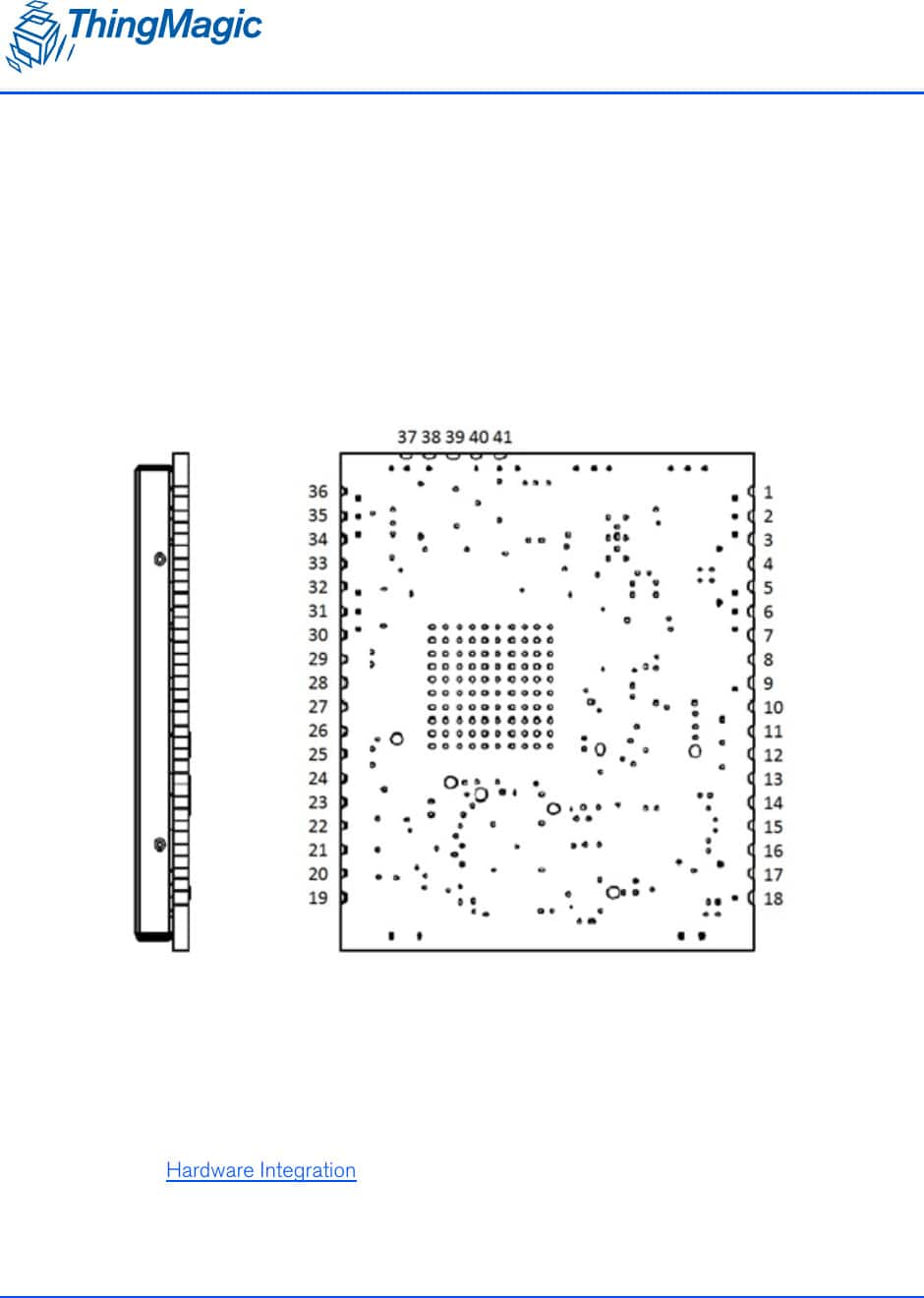
Module Pin-out
Connections are made to the module using 41 edge pads (“vias”) that allow the module to
be surface mounted to a main board. Here is a bottom viewof the module, showing the
numerical interfaces of the module:
The document sections that follow explain in detail how these connections are used.
Antenna Connections
The ThingMagic Nano supports one monostatic bidirectional RF antenna through edge
vias. See Hardware Integrationfor antenna edge via locations and layout guidelines.
The maximum RF power that can be delivered to a 50 ohm load from each port is 0.5
Watts, or +27 dBm (regulatory requirements permitting).
 fifhmgMaglc
Hardware Interfaces
A DIVISION OF TRIMBLE
Hardware Overview23
Antenna Requirements
The performance of the ThingMagic Nano is affected by antenna quality. Antennas that
provide good 50 ohm match at the operating frequency band perform best. Specified
performance is achieved with antennas providing 17 dB return loss (VSWR of 1.33) or
better across the operating band. Damage to the module will not occur for any return loss
of 1 dB or greater. Damage may occur if antennas are disconnected during operation or if
the module sees an open or short circuit at its antenna port.
Antenna Detection
CAUTION!
!!
Like the Micro module, but unlike the M6e and M5e modules, the Thing-
Magic Nano does not support automatic antenna detection. When writ-
ing applications to control the ThingMagic Nano you must explicitly
specify that antenna 1 is to be used. Using the MercuryAPI, this requires
creation of a “SimpleReadPlan” objectwith the list of antennas set and
that object set as the active /reader/read/plan. For more information see
the MercuryAPI Programmers Guide | Level 2 API | Advanced Reading |
“ReadPlan”section.
 fifhmgMaglc
Hardware \ntegrahon
Hardware Interfaces
A DIVISION OF TRIMBLE
24 Hardware Overview
Digital/Power Interfaces
The edge “via” connections provides power, serial communications signals, an enable
control, and access to the GPIO lines to the ThingMagic Nano module.
See HardwareIntegrationfor pinout details of both connections and layout guidelines
 @IhingMagic
Hardware Interfaces
A DIVISION OF TRIMBLE
Hardware Overview25
ThingMagic Nano Digital Connector Signal Definition
Edge Via
Pin #Signal
Signal
Direction
(In/Out of
ThingMagic
Nano)
Notes
1-9, 18-19GNDSignal ReturnMust connect all GND pins to ground
as they also serve to remove heat
from the module
10VoutDC Power
Output
3.4V DC output. Maximum load 5 mA.
Turns off when ENABLE is pulled low.
Leave unconnected if not used.
11 ENABLEEnable/Shut-
down
TTL input that turns the module off
and reduces its power consumption to
nearly zero.
Hi=Enable, Low=Shutdown module
If left unconnected, module will stay in
ENABLE state.
12GPIO1Bidirectional
GPIO
Each line configurable as input or out-
put interface (by default it is an input
with internal pull-down).
13GPIO2Bidirectional
GPIO
14GPIO3Bidirectional
GPIO
15GPIO4Bidirectional
GPIO
16,17VinPower Supply
Input
3.3 to 5.5VDC. Pins 16 and 17 are
internally connected. Connect the DC
power source to both pins to ensure
sufficient current carrying capacity.
20UART_TXOutUART Serial output, 3.3V logic
21UART_RXInUART Serial input, 3.3V logic. Must be
low when module is powered on or off.
22-28RFUReservedReserved for future use - leave uncon-
nected
39RFRF Transmit
and Receive
Interface to antenna
37-38, 40-41GNDRF GroundMust connect all GND pins to ground
as they also serve to remove heat
from the module
 §VWThmgMaglc
, no more
than 0.3 V higher
than Vout when
module is turned off
to prevent damage.
Hardware Interfaces
A DIVISION OF TRIMBLE
26 Hardware Overview
The following table gives the Voltage and Current limits for all communication and control
interfaces:
Control Signal Specification
The module communicates to a host processor via a TTL logic level UART serial port,
accessed on the edge “vias”. The TTL logic level UART supports complete functionality.
The USB port supports complete functionality except the lowest power operational mode.
Specification Limits
Input Low-level Voltage1.0 V max to indicate
low state; no lower
than 0.3 V below
ground to prevent
damage
Input High-level Voltage1.9 V min to indicate
high state; 3.7 V max
when module is
powered up, no more
than0.3 V higher
than Vout when
module is turnedoff
to prevent damage.
Output Low-level Voltage0.3 V typ, 0.7 V max
Output High-level Voltage3.0 V typ, 2.7 V min
Output Low-level Current10 mA max
Output High-level Current7 mA max
 fifhmgMaglc
Note
ThmgMagwc Nana Dwgita‘ Connector Swgna‘
Definihon
Hardware Interfaces
A DIVISION OF TRIMBLE
Hardware Overview27
TTL Level UART Interface
Only three pins are required for serial communication (TX, RX, and GND). Hardware
handshaking is not supported.This is a TTL interface; a level converter is necessary to
connect to devices that use a 12V RS232 interface.
The RX line is a 3.3 volt logic CMOS input and is internally pulled up with a resistance
value of between 20 and 60 kOhms (40 kOhms nominal). It must be low before the
module is turned off and low before the module is turned on. This can be insured if
interface drivers are used that are powered by the module itself, as shown in the interface
board example.
The connected host processorʼs receiver must have the capability to receive up to 256
bytes of data at a time without overflowing.
These are the baud rates supported on the interface (bits per second):
– 9600
– 19200
– 38400
– 115200
– 230400
– 460800
– 921600
Note
Upon initial power up, the default baud rate of 115200 will be used. If that
baud rate is changed and saved in the application mode, the new saved
baud rate will be used the next time the module is powered up. (Check the
firmware release notes to confirm that saving of settings is supported.)
General Purpose Input/Output (GPIO)
The four GPIO connections, described in theThingMagic Nano Digital ConnectorSignal
Definition, may be configured as inputs or outputs using the MercuryAPI. The GPIO pins
should connect through 1 kOhm resistors to the module to ensure the input Voltage limits
are maintained even if the module is shut off.
Module power consumption can be increased by incorrect GPIO configuration. Similarly,
the power consumption of external equipment connected to the GPIOs can also be
adversely affected. The following instructions will yield specification compliant operation.
On power up, the ThingMagic Nano module configures its GPIOs as inputs to avoid
contention from user equipment that may be driving those lines. The input configuration is
 §VWThmgMaglc
Hardware Interfaces
A DIVISION OF TRIMBLE
28 Hardware Overview
a 3.3 volt logic CMOS input and is internally pulled down with a resistance value of
between 20 and 60 kOhms (40 kOhms nominal). Lines configured as inputs must be low
whenever the module is turned off and low at the time the module is turned on.
GPIOs may be reconfigured individually after power up to become outputs. Lines
configured as outputs consume no excess power if the output is left open.
Configuring GPIO Settings
The GPIO lines are configured as inputs or outputs through the MercuryAPI by setting the
reader configuration parameters /reader/gpio/inputListand/reader/gpio/outputList. The
state of the lines can be Get or Set using the gpiGet()and gpoSet()methods,
respectively. See the language specific reference guide for more details.
ENABLE Line
CAUTION!
!!
The polarity of the ENABLE line is opposite from the 4-port M6e module.
The ENABLE line (referred to as the SHUTDOWN line in the M6e) must be pulled HIGH
or left unconnected in order for the module to be operational. To shut down the module,
the line is set LOW or pulled to Ground. Switching from high to low to high is equivalent to
performing a power cycle of the module. All internal components of the module are
powered down when ENABLE is set LOW.
 fifhmgMaglc
DC Power Requirements
A DIVISION OF TRIMBLE
Hardware Overview29
DC Power Requirements
The module is specified to operate with DC input levels of between 3.3 and 5.5 V. All
specifications are maintained as long as the total input current is below 1 A. At 1 A, the
internal Voltage regulatorʼs protection circuit allows no more current to be taken in. This
1A current limit will be reached slightly sooner if current is drawn out the Vout line or if the
GPIO lines are supplying current to external circuits.
The most obvious impact of this 1A limit is that the module cannot be operated below 3.7
Volts when the RF power output level is set to 27 dBm. This limit is fully explained in the
next section.
The module will still operate if the DC input Voltage level falls below 3.3 V, but its
specifications are not guaranteed. If the DC input Voltage falls below 3 VDC, a “brown-
out” self-protection function in the processor will gracefully turn the module off so that the
module will not be in an undeterminate state once the voltage is restored.
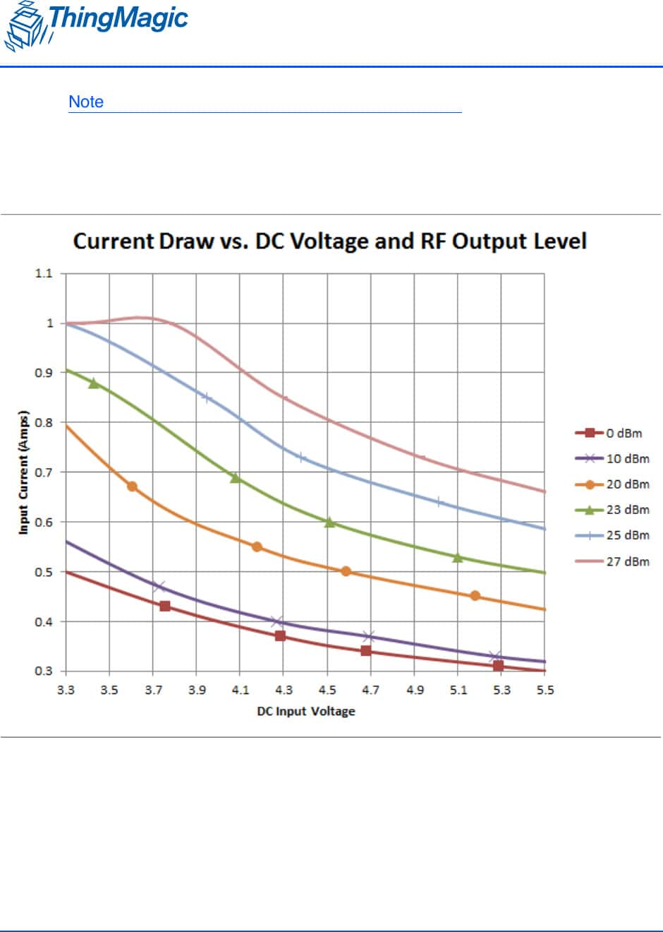
RF Power Output Impact on DC Input Current and Power
The ThingMagic Nano supports separate read and write power level which are command
adjustable via the MercuryAPI. The power level limits are:
– Minimum RF Power = 0 dBm
– Maximum RF Power = +27 dBm
 SéV/l'l'hmgMaglc
Note
Current Draw vs. DC Voltage and RF Output Level
1.1
1 _
\ \
\\ \
”9 \ \ \
E M \\ \ +0 dam
E o \ \_ \\ —x— 10 dBm
7 \\ +20 dam
2 \\ \ \\ -n-zs am
.5" ° 6 —¢— 25 dam
o 5 \\ \\*\\\ —27 dBm
M K> \
‘\::r>\_
DC Power Requirements
A DIVISION OF TRIMBLE
30 Hardware Overview
Note
Maximum power may have tobe reduced to meet regulatory limits, which
specify the combined effect of the module, antenna, cable and enclosure
shielding of the integrated product.
As shown in the chart, the current draw when the RF output level is set to +27 dBm
reaches the limit of 1A when the DC input voltage is below 3.7 V. Below the 3.7 VDC input
level, the RF level will no longer reach 27 dBm, although no error message will be
returned. The input Voltage should be maintained above 3.7 Volts if the RF output power
setting is above +25 dBm. 3.5 V is adequate for an RF output power level of +26 dBm,
and 3.3 V is adequate for an RF output power level of +25 dBm and below. The chart
 S
S
%
fhingMagic
Module Output Punter (darn)
15
~
~1
N
m
k
24
Module Output Power vs Module Voltage
/
/
—0—27 din
-I—7_5 din
3.3
3.5 3.7 3.9 4.1 43 4.5 4.7 4.9 5.1 5.3 5.5
Module Voltage (V)
DC Power Requirements
A DIVISION OF TRIMBLE
Hardware Overview31
below shows the impact of the input DC Voltage on the RF output level for +25 dBm and
+27 dBm RF power levels.
The power drawn by the module is fairly constant, rising slightly as the DC Input Voltage
is lowered. Once the 1A input current limit is reached, the input power appears to
 fifhmgMaglc
Power Consumption vs. DC Voltage and RF
Output level
4.00
3.75
3.50
3.15
a
g ”0 +0 dam
I- +10dBm
175
3 +20 dBm
i 150 —23 dam
.
' 1.15 —.—15 dBm
—27 dBm
33 3.5 3.7 3.9 41 43 4‘5 {7 ‘3 5,1 5.3 5.5
DC Iloul Valli:
Suggorted Regions
DC Power Requirements
A DIVISION OF TRIMBLE
32 Hardware Overview
decrease, but this is because the RF output level is no longer reflecting the desired
setting. This chart shows these dependencies:
Note: Power consumption is defined for operation into a 17 dB return loss load (VSWR of 1.33)
or better. Power consumption may increase, up to 4 W, during operation into return losses
worse than 17 dB and high ambient temperatures. Power consumption will also vary
based on which of the Supported Regionsis in use.
Power Supply Ripple
The following are the minimum requirements to avoid module damage and to insure
performance and regulatory specifications are met. Certain local regulatory specifications
may require tighter specifications.
 \éfl/IhmgMaglc
Id \e DC Power Consumgtion
ENABLE Line
DC Power Requirements
A DIVISION OF TRIMBLE
Hardware Overview33
3.3 to 5.5 VDC
Less than 25 mV pk-pk ripple all frequencies,
Less than 11 mV pk-pk ripple for frequencies less than 100 kHz,
No spectral spike greater than 5 mV pk-pk in any 1 kHz band.
Idle DC Power Consumption
When not actively transmitting, the ThingMagic Nano module falls back into one of 3 idle
states, called “power modes”. There are 5 enumerated idle power modes defined in the
API, but the Nano module only supports 3 options, so three of the settings behave
identically. Each successive power mode turns off more of the moduleʼs circuits, which
have to be restored when a command is executed, imposing a slight delay. The following
table gives the power consumption levels and the delay to respond to a command for
each. See Idle DCPower Consumptionfor details.
These nominal values should be used to calculate metrics such as battery life. To
determine the absolute maximum DC power that would be required under any condition,
one must consider temperature, channel of operation, and antenna return loss.
ThingMagic Nano Power Consumption
Operation
DC Power
Consumed
at 5 VDC
Time to
Respond to
a Read
Command
Power Mode = “FULL”0.85 WLess than 5
msec
Power Mode = “MINSAVE”,
“MEDSAVE”, or “MAXSAVE”
0.04 WLess than 20
msec
Power Mode = “SLEEP”0.02 WLess than 20
msec
ENABLE Linedisabled.00015 WModule
reboots when
Enable line
brought high
 fifhmgMaglc
RF Characteristics
A DIVISION OF TRIMBLE
34 Hardware Overview
RF Characteristics
RF Output Power
The output power may be set to a separate value for read and write operations (for many
tags, more power is required to write to read). The range of values for both settings is
from 0 dBm to +27 dBm, in 0.01 dB increments. (For example, 27 dBm will be configured
as “2700” in units of centi-dBm.) The modules are calibrated when theyare manufactured
in 0.5 dB increments and linear interpolation isused to set values with greater granularity
than this.
The granularity of the RF output power setting should not be confused with its accuracy.
The accuracy of the output level is specified to be +/- 1 dBm for each regional setting.
 @fhmgMaglc
Output Power Accuracy vs. Channel
Frequency
*8663 MHZ
+9114 MHI
+9124 MHZ
Davhtbl [mm “ulna (d!)
*9171 MHZ
02465101114161820122426
PwelSettinfldBm)
RF Power Output Impact on DC Input Current and Power
RF Characteristics
A DIVISION OF TRIMBLE
Hardware Overview35
Additional variation may be experienced if the DC input Voltage and temperature changes
while the module is operational.
This chart shows the typical transmit output variation over frequency. The typical variation
is less than +/-0.5 dBm for all transmit levels, across the entire frequency band.
DC Input Voltage also affects the transmit output level accuracy. The typical variation is
less than +/- 0.20 dBm except at high RF output levels for low DC input voltages, as has
been discussed in the RF Power Output ImpactonDC Input Currentand Powersection.
The following chart shows the accuracy of the RF power setting across all supported input
DC voltages. Note that the actual RF output level starts to drop for +27 dBm output level
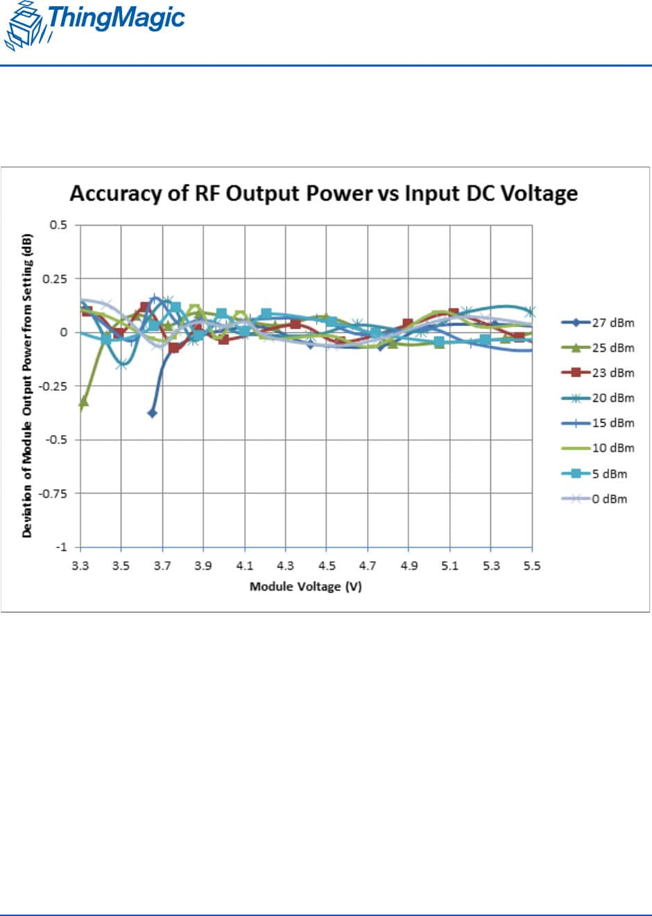 fifhmgMaglc
Accuracy of RF Output Power vs Input DC Voltage
0.5
i
a
u
5
= 0.25
C
u.
E
g +17 dBm
..
g ---15 dBm
._ +13 dBm
.
g +20 dBm
g —¢—15 dBm
E "0‘5 —10 dBm
T: +5 dBm
a
a 0.75 ———0 dBm
'!
8
-1
3.3 355 3‘7 3‘9 451 4,3 4,5 457 455 5.1 5.3 555
Module Vottage (V)
RF Characteristics
A DIVISION OF TRIMBLE
36 Hardware Overview
settings at around 3.7 VDC input levels and the RF output level starts to drop for +25 dBm
settings at around 3.3 VDC input levels.
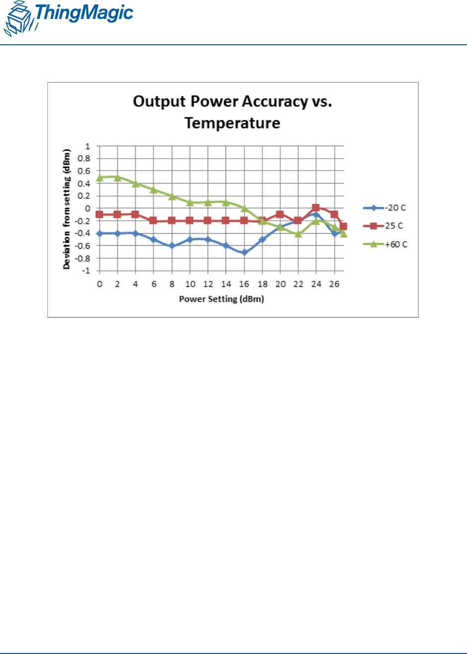
The output accuracy over temperature is typically +/- 0.75 dBm, with most variation
occurring at lower transmit output power levels.
 @fhmgMaglc
Output Power Accuracy vs.
Temperature
S
3
=
E
E —0—-20 C
E +25 c
a ++60 C
i
8
01468101214151510121416
PmrSettingldBm)
RF Characteristics
A DIVISION OF TRIMBLE
Hardware Overview37
Receive Sensitivity
The receive sensitivity is influenced by both user-defined settings and by external
environmental factors. These factors are:
Transmit Level
Gen2 “M” setting
Region of Operation
Receive sensitivity is strongly influenced by the amount of interference caused by the
readerʼs own transmit signal. This interference can be reduced by reducing the transmit
level. ThingMagic always quotes the receive sensitivity at the highest transmit level (+27
dBm for the Nano), but 1 dB of sensitivity is typically gained for every dB that the
transmitter output level is reduced.
The Gen2 “M” setting influences how data is encoded when sent from the tag to the
reader. Higher “M” values send data at lower rates and are more noise immune,
 $1
$1
éW/ThmgMaglc
Region "M” Value Sensitivity
8 757 dBm
MHZ band
8 760 dBm
4 758 dBm
2 749 dBm
RF Characteristics
A DIVISION OF TRIMBLE
38 Hardware Overview
increasing the moduleʼs sensitivity. Lower “M” values send data at higher rates,
decreasing the sensitivity somewhat.
The region of operation is also a factor. The Nano has slightly better receive sensitivity in
the regions that fall within the range of 865 to 868 MHz than in regions that fall within the
range of 917 to 928 MHz.
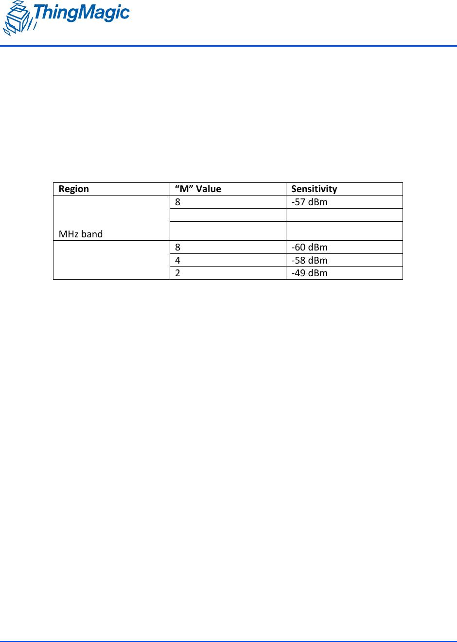
The following table gives the sensitivity for region and “M” value at a transmit output level
of +27 dBm.
Note that sensitivity is strongly affected by the success rate required by the application.
The sensitivity values in the table reflect a very high read success rate (greater than
90%). Tags typically will begin to respond sporadically at receive levels that are 5 dB
lower than the values shown in this table.
Receiver Adjacent Channel Rejection
The ThingMagic Nano receives signals that are centered at +250 kHz from its own
carrier. The width of the receive filter is adjusted to match the “M” value of the signal
being sent by the tag. An M value of 2 require the widest filter and an M value of 8
requires the narrowest filter. If operating in an environment where many readers are
present, observe the performance of one reader as the other readers are turned on and
off. If the performance improves when the other readers are turned off, then the system
may be experiencing reader-to-reader interference. This reader-to-reader interference will
be minimized by using the highest “M” value that is consistent with the tag read rates
required by the application.
Region“M” ValueSensitivity
North America and
subsets of 917 to 928
MHz band
8-57dBm
4-55 dBm
2-45 dBm
EU and India (865 to 868
MHz
8-60dBm
4-58dBm
2-49dBm
 fifhmgMaglc
Environmental Specifications
A DIVISION OF TRIMBLE
Hardware Overview39
Environmental Specifications
Thermal Considerations
The module will operate within its stated specifications over a temperature range o f -20
to +60 degrees C, measured at the ground plane that the ThingMagic Nano module is
soldered to.
It may be safely stored in temperatures ranging from -40 degrees C to +85 degrees C.
Thermal Management
Heat-sinking
For high duty cycles, it is essential to use a surface mount configuration where all edge
vias are soldered to a carrier or mother board, with a large area of ground plane, that will
either radiate heat or conduct the heat to a larger heat-sink. A high density of PCB vias
from the top to bottom of the board will efficiently conduct heat to a bottom mount heat-
sink. Often the weak link in thermal management design is not the thermal interface from
the ThingMagic Nano to the heat-sink, but rather the thermal interface from the heat-sink
to the outside world.
Duty Cycle
If overheating occurs it is recommended to first try reducing the duty cycle of operation.
This involves modifying the RF On/Off (API parameter settings /reader/read/
asyncOnTime and asyncOffTime) values. A good place to start is 50% duty cycle using
250ms/250ms On/Off.
If your performance requirements can be met, a low enough duty cycle can result in no
heat sinking required. Or with adequate heat sinking you can run continuously at 100%
duty cycle.
Temperature Sensor
The ThingMagic Nano module has an integrated temperature sensor, located near the
components which generate the most heat. The temperature can be obtained through the
user interface as a status indication. This information is also used by the firmware to
prevent transmission when the module is too hot or too cold to operate properly. The
temperature limits for allowing transmission are -20 C to +85 C.
 fifhmgMaglc
Note
Environmental Specifications
A DIVISION OF TRIMBLE
40 Hardware Overview
Note
The temperature level at which transmission is prevented, +85 C, is higher
than the +60 C operating limit for two reasons: (1) The temperature indicated
by the on-board sensor willalways be higher than ambient temperature, due
to heat generated by internal components, and (2) the temperature limit for
transmission is chosen to prevent damage to the components, while the +60
C limit for operation is chosen to ensure that all specifications are met.
 fifhmgMaglc
ee Hardware \ntegratxon
Note
E‘ectroStatxc Discharge ESD Consxderations
Environmental Specifications
A DIVISION OF TRIMBLE
Hardware Overview41
Electro-Static Discharge (ESD) Specification
The Electro-Static Discharge Immunity specifications for the ThingMagic Nano are as
follows:
IEC-61000-4-2 and MIL-883 3015.7 discharges direct to operational antenna port
tolerates max 1 KV pulse. It will tolerate a 4 kV air discharge on the I/O and power
lines. It is recommended that protective diodes be placed on the I/O lines as shown in
the carrier board schematic diagram (seeHardwareIntegration).
Note
Survival level varies with antenna return loss and antenna characteristics.
See ElectroStatic Discharge(ESD) Considerationsfor methods to increase ESD
tolerances.
WARNING!
The ThingMagic Nano antenna port may be susceptible to damage from
Electrostatic Discharge (ESD). Equipment failure can result if the
antenna or communication ports are subjected to ESD. Standard ESD
precautions should be taken during installation and operation to avoid
static discharge when handlingor making connections to the
ThingMagic Nano reader antenna or communication ports.
Environmental analysis should also be performed to ensure static is not
building up on and around the antennas, possibly causing discharges
during operation.
Shock and Vibration
The ThingMagic Nano module is specified to survive a 1 meter drop onto a hard surface.
It will also survive the following vibration limits:
4.02 Grms random, mounted on a non-resonant hard carrier
Five shipments by air, MIL-STD-810G METHOD 514.6 ANNEX C, Figure 514.6C-5
General Exposure pg 514.6C-16, and Table 514.6C-VII, General Exposure. 5
minutes each of three axes.
 fifhmgMaglc
Vendor Model Type Polarizallo Frequency Circular Max Linear
(dBiC)
MTI MT»263020 Palch Circular 902928 11 min 8
Wireless MHz
Laird S9025P Palch Circular 902-928 5.5 4.3
MHZ
Laird SSSSSWPL Palch Circular 865960 8.5 6.0
MHZ
MTI MTI-262013 Palch Circular 902928 7 min, 7.5 6.0
Wireless MHz max
MTI MTI-242043 Palch Circular 865956 7.5 in EU 6.0
NA band
Laird FG9026 Dipole Linear 902-928 [Nor 8.15
MHz Applicable]
Authorized Antennas
A DIVISION OF TRIMBLE
42 Hardware Overview
Authorized Antennas
This device has been designed to operate with the antennas listed below, and having a maxi-
mum gain of 8.15dBiL. Antennas not included in this listor having a gain greater than 8.15
dBiLare strictly prohibited for use with this device without regulatory approval. (Circularly polar-
ized antennas can have a circular gain has high as 11.15 dBiC and still maintain a maximum lin-
ear gain of 8.15 dBiL.) The required antenna impedance is 50 ohms.
ThingMagic Nano Authorized Antennas
Note: Most tags are linearly polarized, so the “max linear gain” value is the best number to use
when calculating the maximum read distance between the module and a tag.
FCC Modular Certification Considerations
Trimble has obtained FCC modular certification for the ThingMagic Nano module. This
means that the module can be installed in different end-use products by another
equipment manufacturer with little or no additional testing or equipment authorization for
the transmitter function provided by that specific module. Specifically:
No additional transmitter-compliance testing is required if the module is operated with
one of the antennas listed in the FCC filing
No additional transmitter-compliance testing is required if the module is operated with
the same type of antenna as listed in the FCC filing as long as it has equal or lower
gain than the antenna listed. Equivalent antennas must be of the same general type
(e.g. dipole, circularly polarized patch, etc.), must be of equal or less gain than an
Vendor ModelTypePolarizatio
n
Frequency
Range
Circular
Gain
(dBiC)
Max Linear
Gain (dBi)
MTI
Wireless
MT-263020PatchCircular902-928
MHz
11min8
LairdS9025PPatchCircular902-928
MHz
5.5 4.3
LairdS8658WPLPatchCircular865-960
MHz
8.5 6.0
MTI
Wireless
MTI-262013PatchCircular902-928
MHz
7min,7.5
max
6.0
MTI
Wireless
MTI-242043PatchCircular865-956
MHz
7.5inEU
band, 8.5 in
NA band
6.0
LairdFG9026DipoleLinear902-928
MHz
[Not
Applicable]
8.15
 fifhmgMaglc
ee ThmgMagwc Nana Authorized Antennas
Authorized Antennas
A DIVISION OF TRIMBLE
Hardware Overview43
antenna previously authorized under the same FCC ID, and must have similar in
band and out of band characteristics (consult specification sheet for cut-off
frequencies).
If the antenna is of a different type or higher gain than those listed in the moduleʼs FCC
filing, seeThingMagic NanoAuthorizedAntennas, a class II permissive changemust be
requested from the FCC. Contact us at support@thingmagic.com and we can help you
though this process.
The FCC regulations state that a host device using a module that has a modular grant
can:
1. Be marketed and sold with the module built inside that does not have to be end-user
accessible/replaceable, or
2. Be end-user plug-and- play replaceable.
In addition, a host product is required to comply withall applicable FCC equipment
authorizations, regulations, requirements and equipment functions not associated with
the RFID module portion. For example, compliance must be demonstrated to regulations
for other transmitter components within the host product; to requirements for unintentional
radiators (Part 15B), and to additional authorization requirements for the non-transmitter
functions on the transmitter module (for example, incidental transmissions while in
receive mode or radiation due to digital logic functions).
To ensure compliance with all non-transmitter functions the host manufacturer is
responsible for ensuring compliance with the module(s) installed and fully operational.
For example, if a host was previously authorized as an unintentional radiator under the
Declaration of Conformity procedure without a transmitter certified module and a module
is added, the host manufacturer is responsible for ensuring that the after the module is
installed and operational the host continues to be compliant with Part 15B unintentional
radiator requirements. Since this may depend on the details of how the module is
integrated with the host, we shall provide guidance to the host manufacturer for
compliance with Part 15B requirements.
 é
é
$1
W
/ThingMagic
.—.
m
26
SC'l
AA:
(A)
2 0|
0
i.25 2-33
Width
22 +/70.2 mm
Length
26 +/70.2 mm
Height (includes PCB, shield, mask and |
abels) 3.0 maximum
Mass
3.2 gms
Physical Dimensions
A DIVISION OF TRIMBLE
44 Hardware Overview
Physical Dimensions
The dimensions of the ThingMagic Nano module are shown in the following diagram and
the table below:
AttributeValue
Width22+/-0.2mm
Length26 +/-0.2mm
Height (includes PCB, shield,maskand labels)3.0 maximum
Mass3.2 gms
 fifhmgMaglc
Physical Dimensions
A DIVISION OF TRIMBLE
Hardware Overview45
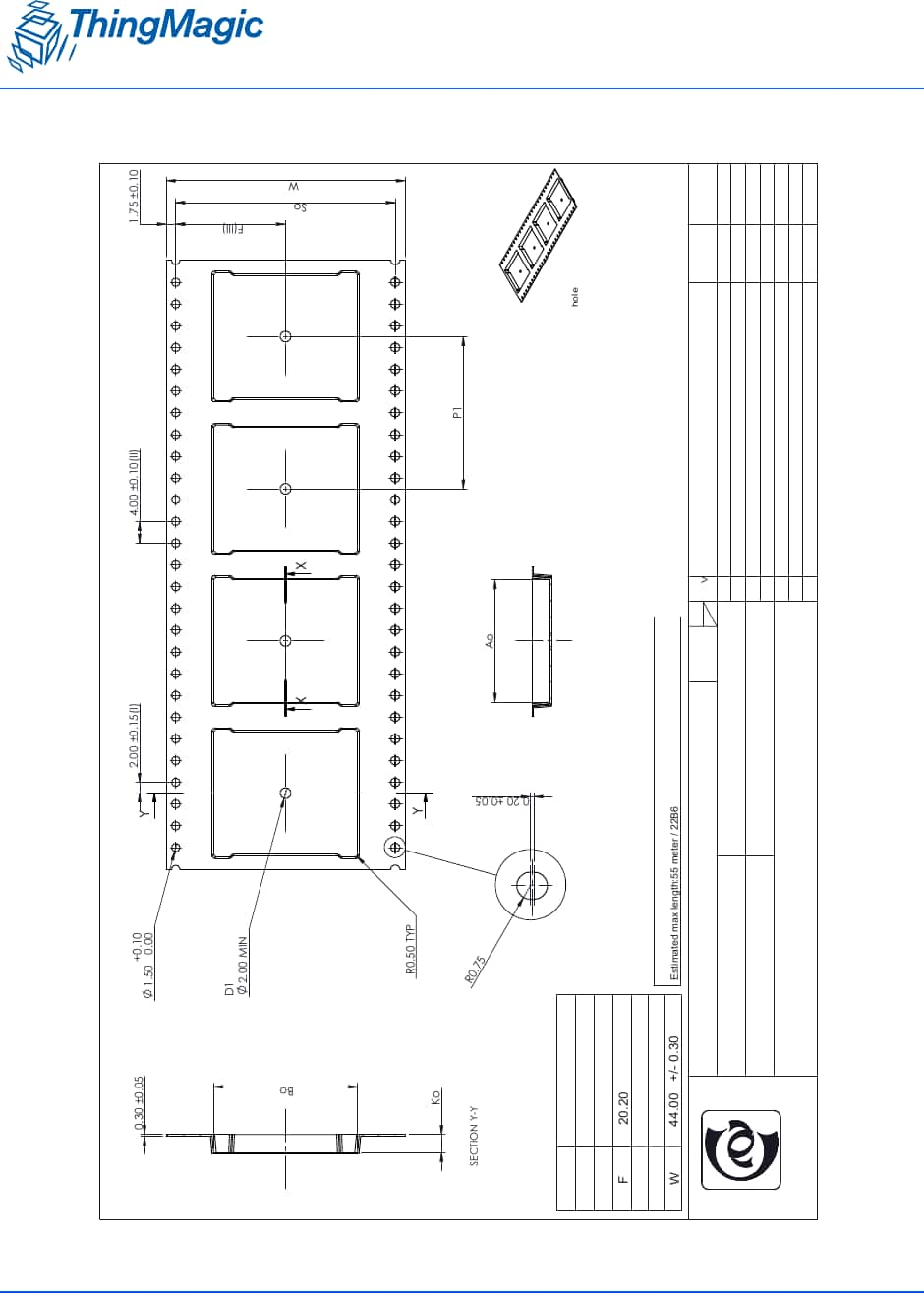
Tape-and-Reel Dimensions
The Nano is delivered in a tape-and-reel package. The reel measures 13 inches by 4
inches. The following drawing gives the dimensions of the tape.
 fifhmgMaglc
Physical Dimensions
A DIVISION OF TRIMBLE
46 Hardware Overview
 fifhmgMaglc
E
£33.02 5.3352353 an a f 8 3 >>
swam n
, ‘
i Aw
. f /
2 a \ y 55:
a \
a
r, \
$$$$$$$$$$$$$$$$$$$$$$$J$$r§
J a , w
M \ iT ; i P ‘71 21‘
w a W
v$$$$®®®$$$v$$fJ
2 mil 7 :2: nannN >
Physical Dimensions
A DIVISION OF TRIMBLE
Hardware Overview47
&3$.37(/7'
70
7+,6'5$:,1*&217$,16,1)250$7,217+$7,635235,(7$5
:
'
0,1
'R
3
,
3R
,,
(
),,,
3
57<3
6R
<
<
;;
7
.R
%R
$R
6(&7,21;;
5
6(&7,21
0HDVXUHGIURPFHQWUHOLQHRIVSURFNHWKROH
WRFHQWUHOLQHRISRFNHW
&XPXODWLYHWROHUDQFHRIVSURFNHW
KROHVLV
0HDVXUHGIURPFHQWUHOLQHRIVSURFNHW
KROHWRFHQWUHOLQHRISRFNHW
,
,,
,,,
,9
2WKHUPDWHULDODYDLODEOH
352326('(0%266('&$55,(57$3(',0(16,216
7,7/(
'5$:,1*12
'5$:1
6&$/(
176
0$7(5,$/
$//',0(16,216,10,//,0(75(681/(6627+(5:,6(67$7('
UG$QJOH
1(:'5$:,1*
'(6&5,37,21
VW$QJOH
5(9
$33529('
'$7(
:
)
*(1(5$/72/(5$1&(
(0
.R
3
32/<67<5(1(,9
:$1*-6
1DQR
:0/((
$R
%R
7RROLQJ&RGH)/$7%('
(VWLPDWHGPD[OHQJWKPHWHU%
6R
 mgMagic
fin
Hm” hwfl
an»:
m
In
m
m
m
m m
n u
m as
as «9
m m
u:
u:
m
m
m
m
In
In
m
"-
m
I"
We WHICH-W .———‘
SMT Reflow Profile
A DIVISION OF TRIMBLE
48 Hardware Overview
SMT Reflow Profile
Short reflow profiles are recommended for soldering processes. Peak zone temperature
should be adjusted high enough to ensure proper wetting and optimized forming of solder
joints.
Generally speaking, unnecessary long exposure and exposure to more than 245C should
be avoided.
To not overstress the assembly, the complete reflow profile should be as short as
possible. An optimization considering all components on the application must be
performed. The optimization of a reflow profile is a gradual process. It needs to be
performed for every paste, equipment and product combination. The presented profiles
are only samples and valid for the used pastes, reflow machines and test application
boards. Therefore a "ready to use" reflow profile can not be given.
There must be only be one reflow cycle, maximum.
 fifhmgMaglc
‘ Host Board Desxgn
‘ ThmgMagwc Nano Carrier Board
A DIVISION OF TRIMBLE
Hardware Integration49
Hardware Integration
The ThingMagic®Nano®embedded module is an RFID reader that you can integrate with
other systems to create RFID-enabled products. This chapter discusses topics relating to
this, including requirements for a host board design and characteristics of the Nano
Carrier Board that ThingMagic offers for use in Development Kits and for applications
where standard connectors are required to interface the module with a host board.
Host BoardDesign
ThingMagicNano Carrier Board
 §$7V/‘I'hlngMaglc
h
Host Board Design
A DIVISION OF TRIMBLE
50 Hardware Integration
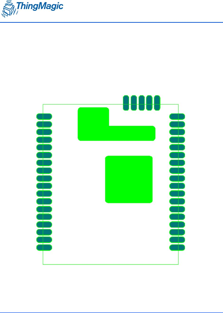
Host Board Design
Landing Pads
This diagram shows the position and recommended size of the landing pads (in dark
green) and the heat-sink areas (in light green):
Hardware design files are available on the Support web site (http://www.thingmagic.com/
manuals-firmware) for the “carrier board” that implements this layout.
 $777”
$777”
ingMagic
Host Board Design
A DIVISION OF TRIMBLE
Hardware Integration51
The ThingMagic Nano module mounts to the host board via the landing pads. These pads
are at a pitch of 1.25 mm. The intention is for the ThingMagic Nano module is to use
routed-through via connections with 0.7 mm diameter edge vias. The pads of the
ThingMagic Nano module underside should align with the copper pads of the footprint,
with a pad exposure extending outside the M6e-Nano edge be a nominal 0.5 mm. A 0.5
mm keep-out shall surround any non-ground pad. The module pad positional tolerance
shall be not more than +/-0.2 mm to support contact alignment during fixturing.
The circuitry feeding the RF pad of the M6e-Nano shall be optimized for connecting to a
coplanar wave guide with ground plane beneath. The CPW-G will have dimensions as
shown in the following diagram.
The area beneath the module should be kept clear of traces and copper.
In addition to the design and process recommendations, the following should be
considered:
PAD 37, GND
PAD 36, GND
Pad 35, RF
PAD 34, GND
PAD 33, GND
NANO Module EdgeCPW-G with:
50 ohm nominal,
0.44 mm Width,
0.40 mm Gap,
0.254 mm Substrate Thickness
Er = 4.4 Nominal
1 ounce copper , Trace and Ground
PAD CLEARANCE
0.5 mm
PAD Typical
2.0 mm x 0.75 mm
1.25 mm pitch
 fifhmgMaglc
Host Board Design
A DIVISION OF TRIMBLE
52 Hardware Integration
There is the potential for 24MHz harmonics radiating from pins 22 through 28 of the
ThingMagic Nano. If emissions testing shows such harmonics, the easiest fix is to
put bypass capacitors (typically 39 to 100pf) directly at the offending pins on the
carrier board. Note that higher values are not necessarily better. The ideal capacitor
value will have series resonance near the most offending frequency. 39pF has been
good for around 900 MHz in sample board layouts.
 \éfl/IhmgMaglc
ThingMagic Nano Carrier Board
A DIVISION OF TRIMBLE
Hardware Integration53
ThingMagic Nano Carrier Board
ThingMagic has created a Carrier Board for the ThingMagic Nano module, as an example
of a host board for this module and to create an assembly that is compatible with the
standard Development Kit main board. It has the size and dimensions of the M6e module
(69 mm x 43 mm), and uses the same connector for power and control (Molex 53261-
1571 - 1.25mm pin centers, 1 amp per pin rating. which mates with Molex housing p/n
51021-1500 with crimps p/n 63811-0300).
The pin definitions are the same as for the M6e module, for the functions that are
supported by the ThingMagic Nano module, with one exception: The “SHUTDOWN” line
 §VWThmgMaglc
ThingMagic Nano Carrier Board
A DIVISION OF TRIMBLE
54 Hardware Integration
of the M6e performs the same function as the ENABLE line in the Nano, but has reversed
polarity.
The UART RX and UART TX lines are buffered on the Nano Carrier Board. This makes
the inputs 5V tolerant and increases the output current driving capability from 10 mA to 15
mA. Diodes are also added on all I/O lines to increase the ESD protection.
The buffer on the Nano Carrier Board is driven by the Vout pin on the ThingMagic Nano.
The current supplied to this buffer will count toward the 1A total current that the
Pin NumberSignal
Signal Direction
with respect to
Carrier Board
Notes
1,2GNDPower and Signal
Return
Must connect both
pins to ground.
3.4DC Power inInput3.3 to 5.5 VDC; must
connect both pins to
the supply.
5GPIO1BidirectionalSame Specifications
as Nano itself.
6GPIO2BidirectionalSame Specifications
as Nano itself.
7GPIO3BidirectionalSame Specifications
as Nano itself.
8GPIO4BidirectionalSame Specifications
as Nano itself.
9UART RXInput
10UART TXOutput
11-13RFUNot Internally Con-
nected
14ENABLEInputInternally Pulled high,
in ENABLE state, if
not connected
15 Unused
 fifhmgMaglc
ThingMagic Nano Carrier Board
A DIVISION OF TRIMBLE
Hardware Integration55
ThingMagic Nano can draw from its power source, potentially requiring slightly higher
input voltage levels to achieve the highest RF output levels.
The following page provides a schematic diagram for the Nano Carrier Board. Contact
support@thingmagic.com to obtain this in a PDF file.
 §VWThmgMaglc
ThingMagic Nano Carrier Board
A DIVISION OF TRIMBLE
56 Hardware Integration
CAUTION!
!!
The RX input line and all GPIO lines configured as inputs must be low
when the module is turned off and low just before the module is turned
on. If input lines are high at the time the module is being powered up,
we have seen corruption of memory occur that cannot be remedied
except at the factory. TheRX input line can be assured to be in a safe
state if it is driven by a buffer circuit that is powered by the Nano module
as shown in the Nano carrier board design. That way, the input Voltage
to the RX pin can never be higher than the DC supply voltage into the
Nano module because the buffer ispowered by the Nano module.
 fifhmgMaglc
ThingMagic Nano Carrier Board
A DIVISION OF TRIMBLE
Hardware Integration57
 @V/
@V/
g /ThingMagic
H>
gnu
H
w” 4>
W
L
1f
D
$ E” #1 ‘v
p
@@@©@@©
ThingMagic Nano Carrier Board
A DIVISION OF TRIMBLE
58 Hardware Integration
5
5
4
4
3
3
2
2
1
1
D D
C C
B B
A A
RF_OUT
SPI_MOSI__USBDM
SPI_CLK__USBDP
SPI_CSN__SCL
SPI_MISO__SDA
SWDIO
SWCLK
RESETN
V3R3
VIN RS232_RX
RS232_TX
SHUTDOWN_N
GPIO1
GPIO2
GPIO3
GPIO4__VSENSE
SWCLK
SWDIOV3R3
RESETN
GND
GND
GND
USB+5
GPIO4__VSENSE
SPI_MOSI__USBDM
SPI_CLK__USBDP
VIN GND
GND
GND
SPI_MOSI__USBDM
SPI_CLK__USBDP
VIN
GPIO1
GPIO2
GPIO3
GPIO4__VSENSE
VIN
USB+5
RS232_RX_EXT
RS232_TX_EXT
SHUTDOWN_N
GND
GND
SHUTDOWN_N
USB+5
VIN
V3R3
RS232_RX_EXT
RS232_TX_EXT
VIN VIN
V3R3 SHUTDOWN_N
RS232_RX_EXT
RS232_TX_EXT
GPIO1
GPIO2
GPIO3
GPIO4__VSENSE
USB+5
SPI_MISO__SDA
SPI_MOSI__USBDM
SPI_CLK__USBDP
SPI_CSN__SCL
SWDIO
SWCLK
RFU11
RFU12
Title
SizeDocument NumberRev
Date:Sheet of
435-0070-01 X3
NANO CARRIER WITH M6E FOOTPRINT
B
11Monday,March 16,2015
Title
SizeDocument NumberRev
Date:Sheet of
435-0070-01 X3
NANO CARRIER WITH M6E FOOTPRINT
B
11Monday,March 16,2015
Title
SizeDocument NumberRev
Date:Sheet of
435-0070-01 X3
NANO CARRIER WITH M6E FOOTPRINT
B
11Monday, March 16, 2015
This tuning gives 0.21 dB IL -29 dB RL
GPIO or USB-5V Sense
DAC_CAPABLE
ADC_CAPABLE
HI=RUN, LOW=SHUTDOWN
JTAG Header
Optional ESD Protection
M6e Interface Pinout
Pin 1 GND
Pin 2 GND
Pin 3 +5V
Pin 4 +5V
Pin 5 GPIO1
Pin 6 GPIO2
Pin 7 GPIO3
Pin 8 GPIO4
Pin 9 RS-232_RX_TTL
Pin 10 RS-232_TX_TTL
Pin 11 USB_DM
Pin 12 USB_DP
Pin 13 USB_5VSENSE
Pin 14 SHUTDOWN
Pin 15 RESET
Jump Pin 1-2 for Shutdown
Leave open for normal operation
Jump Pin 1-2 for USB powered
Leave open for normal operation
CHANGE LOG X3:
1) Change C5, L1 from 22P, 4.7N to 20P, 3.9N.
1) Add PCB1
R5
1.00K
R5
1.00K
U1
TM-NANO
U1
TM-NANO
GND41 41
GND40 40
RF 39
GND38 38
GND37 37
PIN1
1
PIN2
2
PIN3
3
PIN4
4
PIN5
5
PIN6
6
PIN7
7
PIN8
8
PIN9
9
PIN10
10
PIN11
11
PIN12
12
PIN13
13
PIN14
14
PIN15
15
PIN16
16
PIN17
17
PIN18
18 PIN1919
PIN20 20
PIN21 21
PIN22 22
PIN23 23
PIN24 24
PIN25 25
PIN26 26
PIN27 27
PIN28 28
PIN29 29
PIN30 30
PIN31 31
PIN32 32
PIN33 33
PIN34 34
PIN35 35
PIN36 36
MH4MH4
1
1
R9
150NH
R9
150NH
J5
DNP
J5
DNP
1
2
3
J9
20021521-00020
MATES_WITH = 20021444-00020T4LF
J9
20021521-00020
MATES_WITH = 20021444-00020T4LF
2
4
6
8
10
12
14
16
18
20 19
17
15
13
11
9
7
5
3
1
MH7MH7
1
1
R8
1.00K
R8
1.00K
J1
MMCX
J1
MMCX
1
2 3
D2
TVS-4
D2
TVS-4
1
2
3
4
5
MH9MH9
1
1
74LVC2G17
U2
74LVC2G17
U2
1A
1
GND
2
2A
32Y4
VCC 5
1Y 6
J6
53261-1571
J6
53261-1571
M2
M1
1
2
3
4
5
6
7
8
9
10
11
12
13
14
15
C2
DNP
C2
DNP
C4
100P
C4
100P
MH2MH2
1
1
L1
3.9N
L1
3.9N
J4
DNP
J4
DNP
VBUS 1
DN 2
DP 3
ID 4
GND 5
GND6 6
GND7 7
R10 DNPR10 DNP
MH1MH1
1
1
R4
100K
R4
100K
C3
100P
C3
100P
T2
TP SMT
T2
TP SMT
J3
DNP
J3
DNP
1
2
3
MH8MH8
1
1
R6
1.00K
R6
1.00K
J2
CON10A
J2
CON10A
1 2
3 4
5 6
7 8
910
T1
TP SMT
T1
TP SMT
R2
DNP
R2
DNP
R7
1.00K
R7
1.00K
L3
FB100 OHM
L3
FB 100 OHM
D1
TVS-4
D1
TVS-4
1
2
3
4
5
R11 DNPR11 DNP
C5
20P
C5
20P
R3
100K
R3
100K
R1
DNP
R1
DNP
L2
FB 100 OHM
L2
FB 100 OHM
C6
0.1U
C6
0.1U
MH3MH3
1
1
PCB1
450-0070-01_RevX3
PCB1
450-0070-01_RevX3
D3
TVS-4
D3
TVS-4
1
2
3
4
5
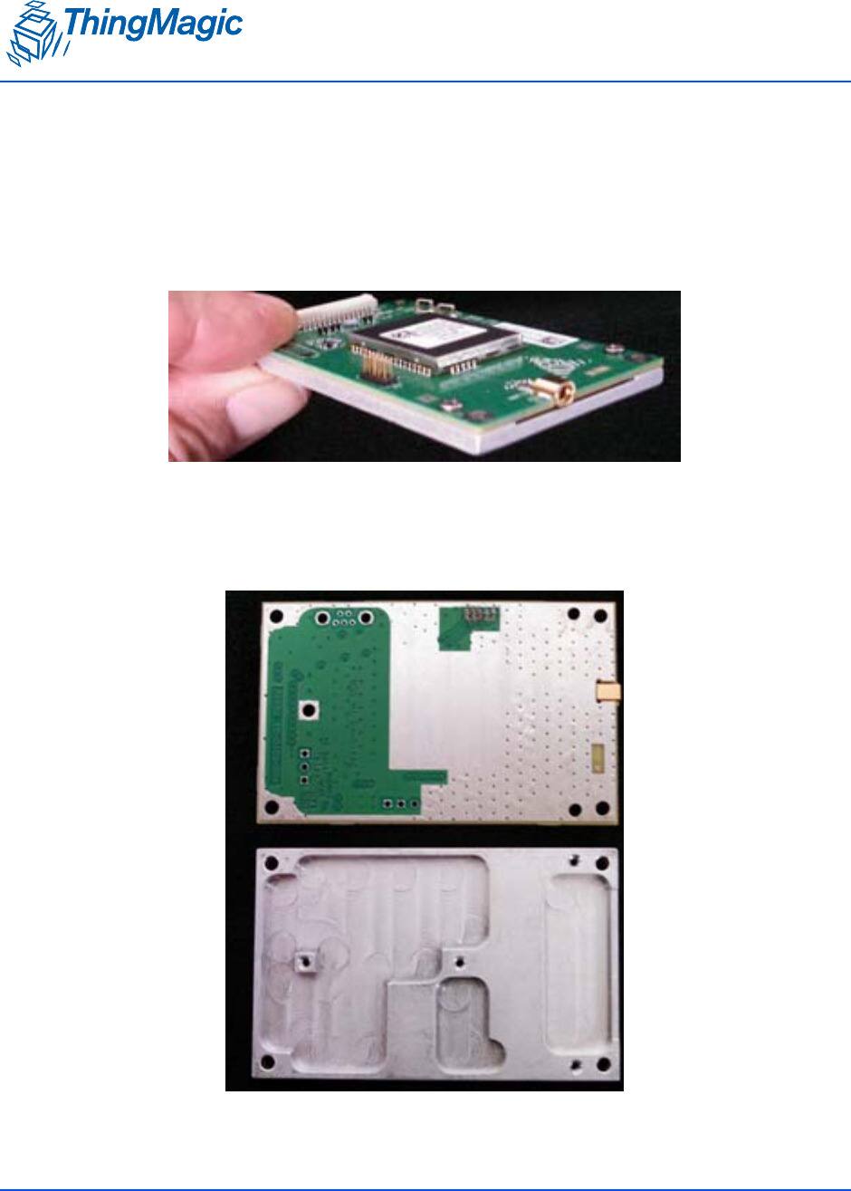 fifhmgMaglc
ThingMagic Nano Carrier Board
A DIVISION OF TRIMBLE
Hardware Integration59
Carrier Board Heat Sinking
The ThingMagic Nano can run at full RF power at room temperature on stand-offs in the
Dev Kit. If you wish to test the ThingMagic Nano under extreme temperature conditions,
you may want to mount it on the heat spreader that is supplied with the Micro modules for
the xPRESS Sensor Hub.
Make sure it is assembled as shown in these pictures so no live signals are shorted to
ground.
 fifhmgMaglc
Note
ThingMagic Nano Carrier Board
A DIVISION OF TRIMBLE
60 Hardware Integration
Note
The Xpress Sensor Hub firmware doesnot support the Thingmagic Nano
module at this time.
 fifhmgMaglc
‘ Boot Loader
‘ Agghcation ermware
‘ Custom OniReaderAgghcatxons
A DIVISION OF TRIMBLE
Firmware Overview61
Firmware Overview
The following section provides detailed description of the ThingMagic Nano firmware
components, including:
Boot Loader
Application Firmware
CustomOn-Reader Applications
 fifhmgMaglc
Agghcation ermware
Note
Note
Boot Loader
A DIVISION OF TRIMBLE
62 Firmware Overview
Boot Loader
The boot loader provides module functionality until the module application firmware can
start up as well as when the module firmware is in the process of being updated. This
program provides the low level hardware support for configuring communication settings,
loadingApplication Firmwareand storing data that needs to be remembered across
reboots.
When a module is powered up or reset, the boot loader code is automatically loaded and
executed.
Note
Unlike the previous generation of ThingMagic modules (M5e and Compact)
the ThingMagic Nano bootloader should effectively be invisible to the user.
The ThingMagic Nano is configured to auto-boot into application firmware
and return transparently tothe bootloader for any operations that require the
module to be inbootloader mode.
Note
Unlike the M6e and Micro (andMicro-LTE) modules, there is no reset line
that can be used to keep the module in bootloader mode when it is
initializing. Likewise, the absence of this reset line means that there is no
hardware indication that the application software has failed to start and the
module has remained in bootloader mode.
 fifhmgMaglc
Application Firmware
A DIVISION OF TRIMBLE
Firmware Overview63
Application Firmware
The application firmware contains the tag protocol code along with all the command
interpreters to set and get system parameters and perform tag operations. The
application firmware is started automatically upon power up.
Programming the ThingMagic Nano
Applications to control the ThingMagic Nano module are written using the high level
MercuryAPI. The MercuryAPI supports Java, “.NET” and C programming environments.
The MercuryAPI Software Development Kit (SDK) contains sample applications and
source code to help developers get started demonstrating and developing functionality.
For more information on the MercuryAPI see the MercuryAPI Programmers Guideand
the MercuryAPI SDK, available on the ThingMagic website.
Upgrading the ThingMagic Nano
New features developed for the ThingMagic Nano are made available through an
Application Firmware upgrade, released with corresponding updates to the MercuryAPI to
make use of the new features. The MercuryAPI SDK contains applications which will
upgrade firmware for all ThingMagic readers and modules, as well as source code that
allows developers to build this functionality into their custom applications.
Verifying Application Firmware Image
The application firmware has an image level Cyclic Redundancy Check (CRC) embedded
in it to protect against corrupted firmware during an upgrade process. If the upgrade is
unsuccessful, the CRC will not match the contents in flash. When the bootloader starts
the application firmware, it first verifies thatthe image CRC is correct. If this check fails,
then the boot loader does not start the application firmware and an error is returned.
 fifhmgMaglc
Custom On-Reader Applications
A DIVISION OF TRIMBLE
64 Firmware Overview
Custom On-Reader Applications
The ThingMagic Nano does not support installing custom applications on the module. All
reader configuration and control is performed using the documented MercuryAPI
methods in applications running on a host processor.
 fifhmgMaglc
‘ Serwal Commumcatxon Protoco‘
‘ User Programmmg \nterface
A DIVISION OF TRIMBLE
Communication Protocol65
Communication Protocol
The following section provides an overview of the low level serial communications
protocol used by the ThingMagic Nano. Topics include:
Serial CommunicationProtocol
User ProgrammingInterface
 §$7V/‘I'hlngMaglc
Serial Communication Protocol
A DIVISION OF TRIMBLE
66 Communication Protocol
Serial Communication Protocol
ThingMagic does not support bypassing the MercuryAPI to send commands to the
ThingMagic Nano module directly, but some information about this interface is useful
when troubleshooting and debugging applicationswhich interface with the MercuryAPI.
The serial communication between MercuryAPI and the ThingMagic Nano is based on a
synchronized command-response/master-slave mechanism. Whenever the host sends a
message to the reader, it cannot send another message until after it receives a response.
The reader never initiates a communication session; only the host initiates a
communication session.
This protocol allows for each command to have its own time-out because some
commands require more time to execute than others. MercuryAPI must manage retries, if
necessary. MercuryAPI must keep track of the state of the intended reader if it reissues a
command.
Host-to-Reader Communication
Host-to-reader communication is packetized according to the following diagram. The
reader can only accept one command at a time, and commands are executed serially, so
the host waits for a reader-to-host response before issuing another host-to-reader
command packet.
HeaderData LengthCommandDataCRC-16
Checksum
HdrLenCmd----------------CRC Hi /
CRC LO
1 byte1 byte1 byte0 to 250
bytes
2 bytes
 @IhingMagic
Serial Communication Protocol
A DIVISION OF TRIMBLE
Communication Protocol67
Reader-to-Host Communication
The following diagram defines the format of the generic Response Packet sent from the
reader to the host. The Response Packet is different in format from the Request Packet.
CCITT CRC-16 Calculation
The same CRC calculation is performed on all serial communications between the host
and the reader. The CRC is calculated on the Data Length, Command, Status Word, and
Data bytes. The header is not included in the CRC.
HeaderData LengthCommandStatus WordDataCRC-16
Checksum
HdrLenCmdStatus Word----------------CRC Hi /
CRC LO
1 byte1 byte1 byte2 bytes0 to 248
bytes
2 bytes
 fifhmgMaglc
User Programming Interface
A DIVISION OF TRIMBLE
68 Communication Protocol
User Programming Interface
The ThingMagic Nano does not support programming to the serial protocol directly. All
user interaction with the ThingMagic Nano must be performed using the MercuryAPI.
The MercuryAPI supports Java, “.NET” and C programming environments. The
MercuryAPI Software Development Kit (SDK) contains sample applications and source
code to help developers get started demoing and developing functionality. For more
information on the MercuryAPI see the MercuryAPI Programmers Guideand the
MercuryAPI SDK, available on the ThingMagic website.
 fifhmgMaglc
A DIVISION OF TRIMBLE
Functionality of the ThingMagic Nano69
Functionality of the ThingMagic Nano
The following section provides detailed descriptions of the ThingMagic Nano features and
functionality that are supported through the MercuryAPI.
 §VWThmgMaglc
Regulatory Support
A DIVISION OF TRIMBLE
70 Functionality of the ThingMagic Nano
Regulatory Support
CAUTION!
!!
Please contact ThingMagic support - support@thingmagic.com - before
beginning the process of getting regulatory approval for a finished prod-
uct using the ThingMagic Nano. We can supply documents, test reports
and certifications to the test house,which will greatly accelerate the
process.
Supported Regions
The ThingMagic Nano has varied levels of support for operation and use under the laws
and guidelines of several regions. The existing regional support and any regulatory
 fifhmgMaglc
Regiona‘ Freguency Sgecxficahons
Regulatory Support
A DIVISION OF TRIMBLE
Functionality of the ThingMagic Nano71
constraints are provided in the following table. Additional information on each region is
provided in Regional Frequency Specifications.
RegionRegulatory SupportNotes
Narrow Band North
America (“NA2”)
FCC 47 CFG Ch. 1 Part 15
Industrie Canada RSS-210
Complies with all FCC regulations but uses a
narrow frequency range: 917,400 kHz to
927,200 kHz
European Union
(“EU3”)
Revised ETSI EN 302 208
Note: The EU and EU2
regions offered for
other modules are for
legacy applications
using old ETSI
regulations. These
are not supported in
the Nano.
By default EU3 will use four channels. The EU3
region can also be used in a single channel
mode. These two modes of operation are
defined as:
Single Channel Mode
Set by manually setting the frequency hop table
to a single frequency. In this mode the module
will occupy the set channel for up to four sec-
onds, after which it will be quiet for 100msec
before transmitting on the same channel again.
Multi Channel Mode
Set by default or by manually setting more than
one frequency in the hop table. In this mode the
module will occupy one of the configured chan-
nels for up to four seconds, after which it may
switch to another channel and immediately
occupy that channel for up to four seconds. It
will not return to any channel until that channel
has been dormant for 100 msec. This mode
allows for more continuous reading.
Korea (KR2)KCC (2009)The first frequency channel (917,300kHz) of the
KR2 region is derated to a maximum level of
+22 dBm to meet the regulatory requirements.
All other channels operate up to +27dBm. This
has little impact on performance. The reader, by
default, automatically switches off channels
when no tags are found, often in as little as 40
msec.
India (IN)Telecom Regulatory Authority
of India (TRAI), 2005 regula-
tions
 §VWThmgMaglc
Regxona‘ Freguency
Sgecxficatxons
Freguency Hop Tab‘e
Frequency Seltmg
Regulatory Support
A DIVISION OF TRIMBLE
72 Functionality of the ThingMagic Nano
The region of operation is set using the MercuryAPI. Setting the region of operation
configures the regional default settings including:
Loads the Frequency Hop Tablewith the appropriate table for the selected region.
Sets the PLL Frequency Settingto the first entry in the hop table, even if the RF is off.
Selects the transmit filter, if applicable.
Frequency Setting
The modules have a PLL synthesizer that sets the modulation frequency to the desired
value. Whenever the frequency is changed, the module must first power off the
modulation, change the frequency, and then turn on the modulation again. Since this can
Peopleʼs Republic of
China (PRC)
SRRC, MII The PRC specifications defines more channels
than are in the Nanoʼs default hop table. This is
because the regulations limit channels from 920
to 920.5MHz and from 924.5 to 925.0MHz to
transmit levels of 100mW and below. The
default hop table uses only the center channels
which allow 2W ERP, 1W conducted, power out-
put. If the hop table is modified to use the outer,
lower power channels the RF level will be limited
to the outer channels limit, 100mW (+20dBm)
Australia (AU)ACMA LIPD Class Licence
Variation 2011 (No. 1)
New Zealand (NZ)Radiocommunications Regula-
tions (General User Radio
Licence for Short Range
Devices) Notice 2011
This region is included for testing purposes.
Compliance to New Zealand regulatory require-
ments has not been confirmed.
Japan (JP)Japan MIC “36dBm EIRP
blanket license radio station
with LBT”
Full power operation restricts the channel range
from 916.8Mhz to 920.8MHz and all default
channels are within this range.
Per the regulations, this region supports Listen-
before-talk at the required level of -74 dBm.
Open RegionNo regulatory compliance
enforced
This region allows the module to be manually
configured within the full capabilities supported
by the hardware, see Regional Frequency
Specificationstable. The Open region should
be used for laboratory testing only as it does not
meet any regulatory requirements for any one
region.
 fifhmgMaglc
Regulatory Support
A DIVISION OF TRIMBLE
Functionality of the ThingMagic Nano73
take 7 to 10 milliseconds, all passive tagswill enter the power-down state during a
frequency hop, which affects their behavior, per the EPCglobal Gen2 specification.
The ThingMagic Nano supports commands that allow channels to be removed from the
hop table and additional channels to be defined (within limits)
Frequency Units
All frequencies in the ThingMagic Nano are expressed in kHz using unsigned 32-bit
integers. For instance, a carrier frequency of 918 MHz is expressed as “918000” kHz.
Each region has a defined lower channel limit, minimum separation between channels
(“quantization”) and an upper channel limit. The user is allowed to enter any channel
frequency, with kHz granularity, as long as it is between the upper and lower channel
limits for that region. The actual frequency used by the module is that of the closest
permitted channel that matches the specified value, which is based on the lower channel
limit plus an integer multiple of the quantization value. Each region has a quantization
value based on regulatory specifications. The following table provides the channel setting
limits for each region setting.
CAUTION!
!!
Use these commands with extreme caution.
It is possible to change the moduleʼs com-
pliance with the regional channel settings.
 §VWThmgMaglc
Regulatory Support
A DIVISION OF TRIMBLE
74 Functionality of the ThingMagic Nano
Regional Frequency Specifications
When manually setting frequencies the module will round down for any value that is not
an even multiple of the supported frequency quantization.
For example: In the NA region, setting a frequency of 917,599 kHz results in a setting of
917,400 kHz.
When setting the frequency of the module, any frequencies outside of the valid range for
the specified region are rejected.
Frequency Hop Table
The frequency hop table determines the frequencies used by the ThingMagic Nano when
transmitting. The hop table characteristics are:
Contains up to 62 entries.
Must be within the frequency range for the region currently selected.
Changes are not stored in flash, thus changes made are not retained after a power
cycle, including when the ENABLE line is activated after having been in the shutdown
state.
Individual entries cannot be changed without reloading the entire table.
Region
Frequency
Quantization
(kHz)
Lowest
Channel
Limit (kHz)
Highest
Channel
Limit (kHz)
Number of
Channels in
Default Hop
Table
NA2 (Reduced FCC)200917,400 kHz927,200 kHz50
EU3 (ETSI)100865,600 kHz867,600 kHz4
IN (India)100865,000 kHz867,000 kHz5
KR2 (Korea)100917,000 kHz923,500 kHz6
PRC125920,125 kHz924,875 kHz16
AU (Australia)250920,000 kHz926,000 kHz10
NZ (New Zealand)250922,000 kHz927,000 kHz11
JP (Japan)100916,900 kHz923,400 kHz6
Open100859,000 kHz
915,000 kHz
873,000 kHz
930,000 kHz
15
16
 fifhmgMaglc
Regulatory Support
A DIVISION OF TRIMBLE
Functionality of the ThingMagic Nano75
Frequencies are used in the order of entries in the table, so if a random order is
required, the frequencies must be pre-randomized before entering.
If necessary for a region, the hop table are randomized to create a pseudo-random
sequence of frequencies to use. This is done automatically using the default hop tables
provided for each region.
 §VWThmgMaglc
Note
Protocol Support
A DIVISION OF TRIMBLE
76 Functionality of the ThingMagic Nano
Protocol Support
Unlike the M6e and Micro modules, the ThingMagic Nano does not have the ability to
support tag protocols other then EPCglobal Gen2 (ISO 18000-6C). Future support for
newer versions of the Gen2 protocol, such as ISO 18000-63 (Gen2V2), are possible.
Gen2 (ISO 18000-6C) Protocol
Gen2 Protocol Configuration Options
The ThingMagic Nano supports limited ISO-18000-6C profiles, with only the Backscatter
Link Frequency (BLF) and “M” value as configurable options. The protocol options are set
in the MercuryAPI Reader Configuration Parameters (/reader/gen2/*). The following table
shows the supported combinations:
Note
When continuously reading, it is important that the data transfer rate from
the host to the module is faster thanthe rate at which tag information is
being collected by the module. This is assured if the reader/baudRate
setting is greater than the BLF divided by the “M” value. If itʼs not, then the
reader could be reading data faster than the host can off-load it, and the
readerʼs buffer might fill up.
Backscatter
Link Frequency
(kHz)
Encoding Tari
(usec)
Modulation
Scheme Notes
250Miller (M=8)25PR-ASKUp to 85 tags per sec-
ond read rate
250Miller (M=4)25PR-ASKDefault; Up to 170 tags
per second read rate.
250Miller (M=2)25PR-ASKUp to 240 tags per
second read rate.
 fifhmgMaglc
Protocol Support
A DIVISION OF TRIMBLE
Functionality of the ThingMagic Nano77
Unsupported Gen2 Functionality
The ThingMagic Nano module firmware can perform some Gen2 functions as a stand-
alone command, but cannot do so as part of an embedded TagOps command: Here is
the list of supported standard Gen2 functions:
Most of the multi-antenna functions are supported because the Nano has the ability to
support a 1:4 multiplexer, creating 4 logical ports from its one physical port.
Unsupported Custom Gen2 Functions
The ThingMagic Nano module does not support many of the custom commands which
are supported in the other module families. Functionality NOTsupported includes:
Higgs 2 FullLoadImage
Higgs 2 PartialLoadImage
Higgs 3 FastLoadImage
Higgs 3 LoadImage
Higgs 3 BlockReadLock
NXP G2X and G2i Set/Reset ReadProtect
NXP G2X and G2i Change EAS and Alarm
Function As Embedded
TagOPs
As Stand-alone
TagOPs
Gen2 Read DataYesYes
Gen2 Write TagNoYes
Gen2 Write DataNoYes
Gen2 Lock TagNoYes
Gen2 Kill TagNoYes
Gen2 Block WriteNoYes
Gen2 Block EraseNoYes
Gen2 Block Perma-
lock
No Yes
Secure Read DataNoNo
 fifhmgMaglc
Protocol Support
A DIVISION OF TRIMBLE
78 Functionality of the ThingMagic Nano
NXP G2X and G2i Calibrate
NXP G2i ChangeConfig
Monza 4QT ReadWrite
AMS/IDS SL900A Sensor Tag Commands
 é
é
S
fl/
fhingMagic
Unsupported Features
A DIVISION OF TRIMBLE
Functionality of the ThingMagic Nano79
Unsupported Features
Unlike other ThingMagic modules, the ThingMagic Nano module currently does not
support gathering reader statistics independent of the meta data that can be
gathered with tag reads. The statistics notsupported include:
RF On-time
Noise Floor,
Noise Floor with Transmit On
Frequency
Temperature
Antenna Ports
Current Protocol
The ThingMagic Nano module currently does not support Save and Restore of
settings.
“User Mode”, which is a little-used feature of older modules, is not supported.
Any commands that involve multiple physical antennas are not supported.
Antenna detection is not supported (The M6e module supports this, the Nano and
Micro modules do not).
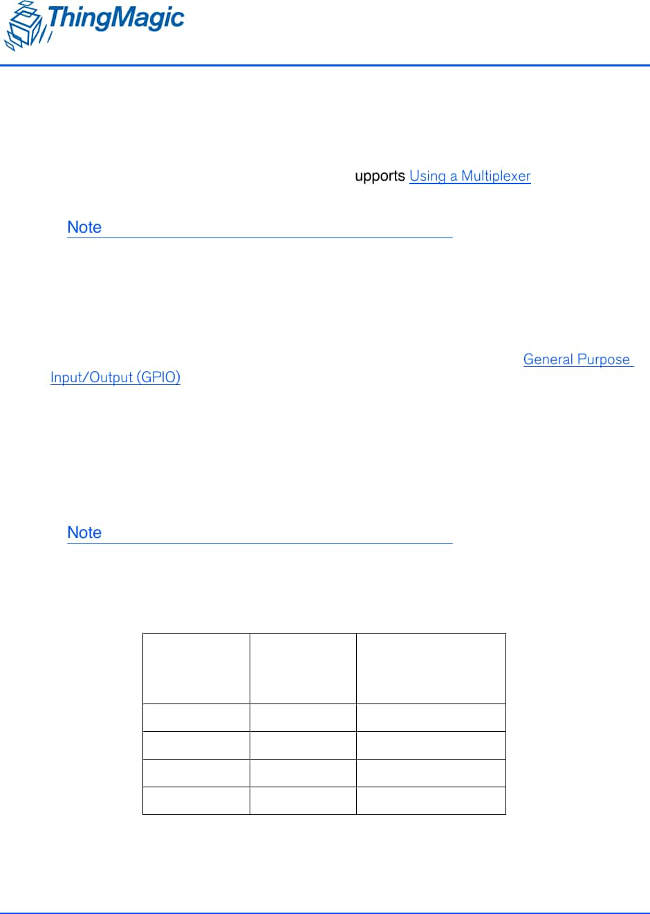 §VWThmgMaglc
upports Usmg a Mu‘twg‘exer
Note
Genera‘ Purpose
\ngut/Outgut G PIO
Note
Antenna Port
A DIVISION OF TRIMBLE
80 Functionality of the ThingMagic Nano
Antenna Port
The ThingMagic Nano has one monostatic antenna port. This port is capable of both
transmitting and receiving. The module also supportsUsing a Multiplexer, allowing up to 4
total logical antenna ports, controlled using two GPIO lines.
Note
The ThingMagic Nano does not support bistatic (separate transmit and
receive port) operation.
Using a Multiplexer
Multiplexer switching is controlled through the use of one or two of the General Purpose
Input/Output (GPIO)lines. In order to enable automatic multiplexer port switching the
module must be configured to use Use GPIO as Antenna Switchin /reader/antenna/
portSwitchGpos.
Once the GPIO line(s) usage has been enabled the following control line states are
applied when the different Logical Antenna settings are used. The tables below show the
mapping that results using GPIO 1 and 2 for multiplexer control (as is used by the
ThingMagic 1 to 4 multiplexer) allowing for 4 logical antenna ports.
Note
The Logical Antenna values are static labels that correspond to the control
line states. The mapping is shown here:
GPIO 1 & 2 Used for Antenna Switching
If only one GPIO Output line is used for antenna control, the combinations of the available
output control line states (the GPIO line in use and the module port) result in a subset of
logical antenna settings which can be used.
GPIO
Output 1
State
GPIO
Output 2
State
Logical Antenna
Setting
Low Low1
Low High2
High Low3
High High4
 fifhmgMaglc
Note
Antenna Port
A DIVISION OF TRIMBLE
Functionality of the ThingMagic Nano81
ONLY GPIO 1 Used for Antenna Switching
ONLY GPIO 2 Used for Antenna Switching
MercuryAPI allows you to assign your own port numbers to these logical ports so that the
port labels are not confusing to the user.
By default, antennas are activated sequentially, from lowest tohighest, returning to the
lowest whenever a new read command is executed. The user can define a port list if they
wish to change this order.
Port Power and Settling Time
The ThingMagic Nano allows the power and settling time for each logical antenna to be
set using the reader configuration parameters/reader/radio/portReadPowerList
and /reader/antenna/settlingTimeList, respectively.
Note
Settling time is the timebetween the control linesswitching to the next
antenna setting and RF turning on for operations on that port. This allows
time for external multiplexerʼs to fully switch to the new port before a signal is
sent, if necessary. Default value is 0.
GPIO
Output 1
State
Logical Antenna
Setting
Low 1
High 3
GPIO
Output 2
State
Logical Antenna
Setting
Low 1
High 2
 §VWThmgMaglc
Tag Buffer
Tag Streammg/Contmuous Reading
Tag Read Meta Data
Tag Handling
A DIVISION OF TRIMBLE
82 Functionality of the ThingMagic Nano
Tag Handling
When the ThingMagic Nano performs inventory operations (MercuryAPI Read
commands) data is stored in aTagBufferuntil retrieved by the client application, or data is
streamed directly to the host if operating in Tag Streaming/Continuous Readingmode.
Tag Buffer
The ThingMagic Nano uses a dynamic buffer that depends on EPC length and quantity of
data read. As a rule of thumb it can store a maximum of 48 96-bit EPC tags in the Tag
Buffer at a time. Since the ThingMagic Nano supports streaming of read results the buffer
limit is, typically, not an issue. Each tag entry consists of a variable number of bytes and
consists of the following fields:
The Tag buffer acts as a First In First Out (FIFO) — the first Tag found by the reader is
the first one to be read out. Duplicate tag reads do not result in additional entries - the tag
count is simply incremented, and the meta-data revised if necessary.
Tag Streaming/Continuous Reading
When reading tags during asynchronous inventory operations (MercuryAPI
Reader.StartReading()) using an /reader/read/asyncOffTime=0 the ThingMagic
Nano “streams” the tag results back to the host processor. This means that tags are
pushed out of the buffer as soon as they are put into the buffer by the tag reading
process. The buffer is put into a circular mode that keeps the buffer from filling. This
allows for the ThingMagic Nano to perform continuous search operations without the
need to periodically stop reading and fetch the contents of the buffer. Aside from not
seeing “down time” when performing a read operation this behavior is essentially invisible
to the user as all tag handling is done by the MercuryAPI.
Total Entry
Size Field SizeDescription
68 bytes
(Max EPC
Length = 496bits)
EPC
Length
2 bytesIndicates the actual EPC length of the tag
read.
PC Word2 bytesContains the Protocol Control bits for the tag.
EPC62 bytesContains the tagʼs EPC value.
Tag CRC2 bytesThe tagʼs CRC.
Additional Tag Read Meta Data
 fifhmgMaglc
Note
The TTL Leve‘ UART Interface
Tag Handling
A DIVISION OF TRIMBLE
Functionality of the ThingMagic Nano83
Note
TheTTL Level UARTInterfacedoes not support control lines, so it is not
possible for the module to detect a broken communications interface
connection and stop streaming the tag results. Nor can the host signal that it
wishes tag streaming to stop temporarily without stopping the reading of
tags.
 §VWThmgMaglc
Usmg a Mum
glexer
Tag Read Meta Data
A DIVISION OF TRIMBLE
84 Functionality of the ThingMagic Nano
Tag Read Meta Data
In addition to the tag EPC ID resulting from ThingMagic Nano inventory operation each
TagReadData(see MercuryAPI for code details) contains meta data about how, where
and when the tag was read. The specific meta data available for each tag read is as
follows:
Meta Data FieldDescription
Antenna IDThe antenna on with the tag was read. WhenUsing a Multi-
plexer, if appropriately configured, the Antenna ID entry will
contain the logical antenna port of the tag read. If the same tag
is read on more than one antenna there will be a tag buffer
entry for each antenna on which the tag was read.
Read CountThe number of times the same tag was read on the same
antenna (and, optionally, with the same embedded data
value).
TimestampThe time the tag was read, relative to the time the command to
read was issued, in milliseconds. If the Tag Read Meta Data is
not retrieved from the Tag Buffer between read commands
there will be no way to distinguishorder of tags read with dif-
ferent read command invocations.
Tag DataWhen reading an embedded TagOpis specified for a Read-
Planthe TagReadData will contain the first 128 words of data
returned for each tag.
Note: Tags with the same TagID but different Tag Data
can be considered unique and each get a Tag
Buffer entry if set in the reader configuration
parameter /reader/tagReadData/
uniqueByData. By default it is not.
FrequencyThe frequency on which the tag was read
Tag PhaseNot supported in ThingMagic Nano
LQI/RSSIThe receive signal strength of the tag response in dBm. For
duplicate entries, the user can decide if the meta data repre-
sents the first time the tag was seen or reflects the meta data
for the highest RSSI seen.
GPIO StatusThe signal status (High or Low) of all GPIO pins when tag was
read.
 fifhmgMaglc
Power Modes
|d\e DC Power Consumgtxon
Note
Event Resgonse Twmes
Power Management
A DIVISION OF TRIMBLE
Functionality of the ThingMagic Nano85
Power Management
The ThingMagic Nano is designed for power efficiency and offers several power
management modes. When transmitting, the power consumption can be minimized by
using the lowest RF power level that meets the application requirements, and powering
the module with highest DC input Voltage.
A “Power Mode” setting determines the power consumed during periods that the module
is not actively transmitting. PowerModes- is set in /reader/powerMode.
Power Modes
The Power Mode setting (set in /reader/powerMode) allows the user to trade off
increased RF operation startup time for additional power savings. Our terminology can be
a little confusing. “MINSAVE” refers to the minimum amount of power saving applied,
which results in a higher idlepower level than “MAXSAVE”.
The details of the amount of power consumed in each mode is shown in the table under
Idle DC Power Consumption. The behavior of each mode and impact on RF command
latency is as follows:
PowerMode.FULL– In this mode, the unit operates at full power to attain the best
performance possible. This mode is intended for use in cases where power
consumption is not an issue. This is the default Power Mode at startup.
PowerMode.MINSAVE– This mode may add up to 20 ms of delay from idle to RF-on
when initiating an RF operation. It performs more aggressive power savings, such as
automatically shutting down the analog section between commands, and then
restarting it whenever a tag command is issued. MEDSAVEand MAXSAVEare the
same as MINSAVE
PowerMode.SLEEP– This mode essentially shuts down the digital and analog
boards, except to power the bare minimum logic required to wake the processor.This
mode may add up to 20 ms of delay from idle to RF on when initiating an RF
operation. (There is no known disadvantage to using SLEEPmode rather than any of
the M**SAVEmodes, since their wake-up times are nearly identical.)
Note
See additional latency specifications under Event Response Times.
 fifhingMagic
Performance Characteristics
A DIVISION OF TRIMBLE
86 Functionality of the ThingMagic Nano
Performance Characteristics
Event Response Times
The following table provides information on how long common ThingMagic Nano
operations take. An event response time is defined as the maximum time from the end of
a command to the beginning of the action the command enables. For example, whenever
appropriate, the time represents the delay between the last byte of a read command and
the moment when an RF signal is detected at the antenna.
Event Response Times
Start Command/
Event End Event
Typical
Time
(msec)
Notes
Power UpApplication Active (with
CRC check)
140This longer power up period should only
occur for the first boot with new firm-
ware.
Power UpApplication Active28Once the firmware CRC has been veri-
fied subsequent power ups do not
require the CRC check be performed,
saving time.
Tag ReadRF On8When in Power Mode = FULL
Tag ReadRF On20When in Power Mode = MINSAVE
Tag ReadRF On20When in Power Mode = SLEEP
 fifhmgMaglc
‘ Common Error Messages
‘ Bootloader FauIts
‘ FIash FauIts
‘ ProtocoI FauIts
‘ Anang Hardware Abstrachon Layer FauIts
‘ Tag ID Buffer Faults
‘ System Errors
FAULT MSG WRONG NUMBER OF DATA7(IOOh)
FAULT INVALID OPCODER IOIh
FAULT UNIMPLEMENTED OPCODE 7 10%
FAULT MSG POWER TOO HIGHP IOBh
FAULT MSG INVALID FREQ RECEIVED 104h
FAULT MSG INVALID PARAMETER VALUE7(105I1)
FAULT MSG POWER TOO LOW7 106h
FAULT UNIMPLEMENTED FEATURE, 109h
FAULT INVALID BAUD RATE? IOAh
Common Error Messages
A DIVISION OF TRIMBLE
Appendix A: Error Messages87
Appendix A: Error Messages
This appendix discusses error messages that you might see in API transport logs or
passed up by the API to the host program. Categories of messages include:
Common Error Messages
Bootloader Faults
Flash Faults
Protocol Faults
Analog HardwareAbstractionLayer Faults
TagIDBufferFaults
SystemErrors
Common Error Messages
The following table lists the common faults discussed in this section.
FAULT_MSG_WRONG_NUMBER_OF_DATA – (100h)
Cause
If the data length in any of the Host-to-module messages is less than or more than the
number of arguments in the message, the reader returns this message.
Fault MessageCode
FAULT_MSG_WRONG_NUMBER_OF_DATA– (100h)100h
FAULT_INVALID_OPCODE –(101h)101h
FAULT_UNIMPLEMENTED_OPCODE –102h102h
FAULT_MSG_POWER_TOO_HIGH– 103h103h
FAULT_MSG_INVALID_FREQ_RECEIVED (104h)104h
FAULT_MSG_INVALID_PARAMETER_VALUE -(105h)105h
FAULT_MSG_POWER_TOO_LOW -(106h)106h
FAULT_UNIMPLEMENTED_FEATURE - (109h)109h
FAULT_INVALID_BAUD_RATE - (10Ah)10Ah
 fifhmgMaglc
Common Error Messages
A DIVISION OF TRIMBLE
88 Appendix A: Error Messages
Solution
Make sure the number of arguments matches the data length.
FAULT_INVALID_OPCODE – (101h)
Cause
The opCode received is invalid or not supported in the currently running program
(bootloader or main application) or is not supported in the current version of code.
Solution
Check the following:
Make sure the command is supported in the currently running program.
Check the documentation for the opCode the host sent and make sure it is correct and
supported.
Check the previous module responses for an assert (0x7F0X) which will reset the
module into the bootloader.
FAULT_UNIMPLEMENTED_OPCODE – 102h
Cause
Some of the reserved commands might return this error code.
This does not mean that they always will do this since ThingMagic reserves the right to
modify those commands at anytime.
Solution
Check the documentation for the opCode the host sent to the reader and make sure it is
supported.
FAULT_MSG_POWER_TOO_HIGH – 103h
Cause
A message was sent to set the read or write power to a level that is higher than the
current HW supports.
 fifhmgMaglc
Common Error Messages
A DIVISION OF TRIMBLE
Appendix A: Error Messages89
Solution
Check the HW specifications for the supported powers and insure that the level is not
exceeded. For the Nano, this limit is +27 dBm.
FAULT_MSG_INVALID_FREQ_RECEIVED (104h)
Cause
A message was received by the reader to set the frequency outside the supported range
Solution
Make sure the host does not set the frequency outside this range or any other locally
supported ranges.
FAULT_MSG_INVALID_PARAMETER_VALUE - (105h)
Cause
The reader received a valid command with an unsupported or invalid value within this
command.
For example, currently the module supports one antenna (without a multiplexer). If the
module receives a message with an antenna value other than 1, it returns this error.
Solution
Make sure the host sets all the values in a command according to the values published in
this document.
FAULT_MSG_POWER_TOO_LOW - (106h)
Cause
A message was received to set the read or write power to a level that is lower than the
current HW supports.
Solution
Check the HW specifications for the supported powers and insure that level is not
exceeded. The ThingMagic Nano supports powers a low limit of 0 dBm.
 fifhmgMaglc
Common Error Messages
A DIVISION OF TRIMBLE
90 Appendix A: Error Messages
FAULT_UNIMPLEMENTED_FEATURE - (109h)
Cause
Attempting to invoke a command not supported on this firmware or hardware.
Solution
Check the command being invoked against the documentation.
FAULT_INVALID_BAUD_RATE - (10Ah)
Cause
When the baud rate is set to a rate that is not specified in the Baud Rate table, this error
message is returned.
Solution
Check the table of specific baud rates and select a baud rate.
 fifhmgMaglc
Bootloader Faults
A DIVISION OF TRIMBLE
Appendix A: Error Messages91
Bootloader Faults
The following table lists the common faults discussed in this section.
FAULT_BL_INVALID_IMAGE_CRC – 200h
Cause
When the application firmware is loaded the reader checks the image stored in flash and
returns this error if the calculated CRC is different than the one stored in flash.
Solution
The exact reason for the corruption could be that the image loaded in flash was corrupted
during the transfer or corrupted for some other reason.
To fix this problem, reload the application code in flash.
FAULT_BL_INVALID_APP_END_ADDR – 201h
Cause
When the application firmware is loaded the reader checks the image stored in flash and
returns this error if the last word stored in flash does not have the correct address value.
Solution
The exact reason for the corruption could be that the image loaded in flash got corrupted
during the transfer or, corrupted for some other reason.
To fix this problem, reload the application code in flash.
Fault MessageCode
FAULT_BL_INVALID_IMAGE_CRC 200h
FAULT_BL_INVALID_APP_END_ADDR 201h
 fifhmgMaglc
FAULT FLASH BAD ERASE PASSWORD 7 BOOh
FAULT FLASH BAD WRITE PASSWORDFSOIh
FAULT FLASH UNDEFINED ERRORFSOQh
FAULT FLASH ILLEGAL SECTORFBOBh
FAULT FLASH WRITE TO NON ERASED AREAFSOAh
FAULT FLASH WRITE TO ILLEGAL SECTORFBOSh
FAULT FLASH VERIFY FAILED7306I1
Flash Faults
A DIVISION OF TRIMBLE
92 Appendix A: Error Messages
Flash Faults
The following table lists the common faults discussed in this section.
FAULT_FLASH_BAD_ERASE_PASSWORD – 300h
Cause
A command was received to erase some part of the flash but the password supplied with
the command was incorrect.
Solution
When this occurs make note of the operations you were executing, save FULL error
response and send a test case reproducing the behavior to support@thingmagic.com.
FAULT_FLASH_BAD_WRITE_PASSWORD – 301h
Cause
A command was received to write some part of the flash but the password supplied with
the command was not correct.
Solution
When this occurs make note of the operations you were executing, save FULL error
response and send a test case reproducing the behavior to support@thingmagic.com.
Fault MessageCode
FAULT_FLASH_BAD_ERASE_PASSWORD – 300h300h
FAULT_FLASH_BAD_WRITE_PASSWORD –301h301h
FAULT_FLASH_UNDEFINED_ERROR – 302h302h
FAULT_FLASH_ILLEGAL_SECTOR–303h303h
FAULT_FLASH_WRITE_TO_NON_ERASED_AREA – 304h304h
FAULT_FLASH_WRITE_TO_ILLEGAL_SECTOR – 305h305h
FAULT_FLASH_VERIFY_FAILED – 306h306h
 fifhmgMaglc
Flash Faults
A DIVISION OF TRIMBLE
Appendix A: Error Messages93
FAULT_FLASH_UNDEFINED_ERROR – 302h
Cause
This is an internal error and it is caused by a software problem in module.
Solution
When this occurs make note of the operations you were executing, save FULL error
response and send a test case reproducing the behavior to support@thingmagic.com.
FAULT_FLASH_ILLEGAL_SECTOR – 303h
Cause
An erase or write flash command was received with the sector value and password not
matching.
Solution
When this occurs make note of the operations you were executing, save FULL error
response and send a test case reproducing the behavior to support@thingmagic.com.
FAULT_FLASH_WRITE_TO_NON_ERASED_AREA – 304h
Cause
The module received a write flash command to an area of flash that was not previously
erased.
Solution
When this occurs make note of the operations you were executing, save FULL error
response and send a test case reproducing the behavior to support@thingmagic.com.
FAULT_FLASH_WRITE_TO_ILLEGAL_SECTOR – 305h
Cause
The module received a write flash command to write across a sector boundary that is
prohibited.
 fifhmgMaglc
Flash Faults
A DIVISION OF TRIMBLE
94 Appendix A: Error Messages
Solution
When this occurs make note of the operations you were executing, save FULL error
response and send a test case reproducing the behavior to support@thingmagic.com.
FAULT_FLASH_VERIFY_FAILED – 306h
Cause
The module received a write flash command that was unsuccessful because data being
written to flash contained an uneven number of bytes.
Solution
When this occurs make note of the operations you were executing, save FULL error
response and send a test case reproducing the behavior to support@thingmagic.com.
 é
é
®
fl/
fhingMagic
FAULT NO TAGS FOUNDP 400h
FAULT NO PROTOCOL DEFINEDP 401h
FAULT INVALID PROTOCOL SPECIFIED 7 40?h
FAULT WRITE PASSED LOCK FAILEDP 403h
FAULT PROTOCOL NO DATA READ7404h
FAULT AFE NOT ON 7405h
FAULT PROTOCOL WRITE FAILED 7406h
FAULT NOT IMPLEMENTED FOR THIS PROTOCOL74O7h
FAULT PROTOCOL INVALID WRITE DATA7408h
FAULT PROTOCOL INVALID ADDRESSP 409h
FAULT GENERAL TAG ERRORP 40Ah
FAULT DATA TOO LARGE 7 4OBh
FAULT PROTOCOL INVALID KILL PASSWORDP 40Ch
FAULT PROTOCOL KILL FAILED , 40Eh
FAULT PROTOCOL BIT DECODING FAILED740Fh
FAULT PROTOCOL INVALID EPC 7 4I0h
FAULT PROTOCOL INVALID NUM DATAP 4I Ih
FAULT GEN? PROTOCOL OTHER ERROR , 4?Oh
FAULT GEN? PROTOCOL MEMORY OVERRUN BAD PCr
4?3h
FAULT GEN? PROTOCOL MEMORY LOCKED , 4?4h
FAULT GEN? PROTOCOL INSUFFICIENT POWER , 4?Bh
FAULT GEN? PROTOCOL NON SPECIFIC ERROR, 4?Fh
FAULT GEN? PROTOCOL UNKNOWN ERROR 7 430h
Protocol Faults
A DIVISION OF TRIMBLE
Appendix A: Error Messages95
Protocol Faults
The following table lists the common faults discussed in this section.
Fault MessageCode
FAULT_NO_TAGS_FOUND – (400h)400h
FAULT_NO_PROTOCOL_DEFINED – 401h401h
FAULT_INVALID_PROTOCOL_SPECIFIED –402h402h
FAULT_WRITE_PASSED_LOCK_FAILED –403h403h
FAULT_PROTOCOL_NO_DATA_READ –404h404h
FAULT_AFE_NOT_ON – 405h405h
FAULT_PROTOCOL_WRITE_FAILED – 406h406h
FAULT_NOT_IMPLEMENTED_FOR_THIS_PROTOCOL–407h407h
FAULT_PROTOCOL_INVALID_WRITE_DATA– 408h408h
FAULT_PROTOCOL_INVALID_ADDRESS –409h409h
FAULT_GENERAL_TAG_ERROR – 40Ah40Ah
FAULT_DATA_TOO_LARGE – 40Bh40Bh
FAULT_PROTOCOL_INVALID_KILL_PASSWORD – 40Ch40Ch
FAULT_PROTOCOL_KILL_FAILED -40Eh40Eh
FAULT_PROTOCOL_BIT_DECODING_FAILED - 40Fh40Fh
FAULT_PROTOCOL_INVALID_EPC –410h410h
FAULT_PROTOCOL_INVALID_NUM_DATA–411h411h
FAULT_GEN2PROTOCOL_OTHER_ERROR - 420h420h
FAULT_GEN2_PROTOCOL_MEMORY_OVERRUN_BAD_PC -
423h
423h
FAULT_GEN2PROTOCOL_MEMORY_LOCKED -424h424h
FAULT_GEN2PROTOCOL_INSUFFICIENT_POWER - 42Bh42Bh
FAULT_GEN2PROTOCOL_NON_SPECIFIC_ERROR -42Fh42Fh
FAULT_GEN2PROTOCOL_UNKNOWN_ERROR - 430h430h
 fifhmgMaglc
Protocol Faults
A DIVISION OF TRIMBLE
96 Appendix A: Error Messages
FAULT_NO_TAGS_FOUND – (400h)
Cause
A command was received (such as like read, write, or lock) but the operation failed. There
are many reasons that can cause this error to occur.
Here is a list of possible reasons that could be causing this error:
No tag in the RF field
Read/write power too low
Antenna not connected
Tag is weak or dead
Solution
Make sure there is a good tag in the field and all parameters are set up correctly. The best
way to check this is to try few tags of the same type to rule out a weak tag. If none
passed, then it could be SW configuration such as protocol value, antenna, and so forth,
or a placement configuration like a tag location.
FAULT_NO_PROTOCOL_DEFINED – 401h
Cause
A command was received to perform a protocol command but no protocol was initially set.
The reader powers up with no protocols set.
Solution
A protocol must be set before the reader can begin RF operations.
FAULT_INVALID_PROTOCOL_SPECIFIED – 402h
Cause
The protocol value was set to a protocol that is not supported with the current version of
SW.
 fifhmgMaglc
Protocol Faults
A DIVISION OF TRIMBLE
Appendix A: Error Messages97
Solution
This value is invalid or this version of SW does not support the protocol value. Check the
documentation for the correct values for the protocols in use and that you are licensed for
it.
FAULT_WRITE_PASSED_LOCK_FAILED – 403h
Cause
During a Write Tag Data for ISO18000-6B or UCODE, if the lock fails, this error is
returned. The write command passed but the lock did not. This could be a bad tag.
Solution
Try to write a few other tags and make sure that they are placed in the RF field.
FAULT_PROTOCOL_NO_DATA_READ – 404h
Cause
A command was sent but did not succeed.
Solution
The tag used has failed or does not have the correct CRC. Try to read a few other tags to
check the HW/SW configuration.
FAULT_AFE_NOT_ON – 405h
Cause
A command was received for an operation, like read or write, but the RF Transmitter was
in the off state.
Solution
Make sure the region and tag protocol have been set to supported values.
 fifhmgMaglc
Protocol Faults
A DIVISION OF TRIMBLE
98 Appendix A: Error Messages
FAULT_PROTOCOL_WRITE_FAILED – 406h
Cause
An attempt to modify the contents of a tag failed. There are many reasons for failure.
Solution
Check that the tag is good and try another operation on a few more tags.
FAULT_NOT_IMPLEMENTED_FOR_THIS_PROTOCOL – 407h
Cause
A command was received which is not supported by a protocol.
Solution
Check the documentation for the supported commands and protocols.
FAULT_PROTOCOL_INVALID_WRITE_DATA – 408h
Cause
An ID write was attempted with an unsupported/incorrect ID length.
Solution
Verify the Tag ID length being written.
FAULT_PROTOCOL_INVALID_ADDRESS – 409h
Cause
A command was received attempting to access an invalid address in the tag data address
space.
Solution
Make sure that the address specified is within the scope of the tag data address space
and available for the specific operation. The protocol specifications contain information
about the supported addresses.
 fifhmgMaglc
httg://
suggortihingmagwocom
Protocol Faults
A DIVISION OF TRIMBLE
Appendix A: Error Messages99
FAULT_GENERAL_TAG_ERROR – 40Ah
Cause
This error is used by the GEN2 module. This fault can occur if the read, write, lock, or kill
command fails. This error can be internal or functional.
Solution
Make a note of the operations you were performing and contact ThingMagic at http://
support.thingmagic.com
FAULT_DATA_TOO_LARGE – 40Bh
Cause
A command was received to Read Tag Data with a data value larger than expected or it is
not the correct size.
Solution
Check the size of the data value in the message sent to the reader.
FAULT_PROTOCOL_INVALID_KILL_PASSWORD – 40Ch
Cause
An incorrect kill password was received as part of the Kill command.
Solution
Check the password.
FAULT_PROTOCOL_KILL_FAILED - 40Eh
Cause
Attempt to kill a tag failed for an unknown reason
Solution
Check tag is in RF field and the kill password.
 fifhmgMaglc
Protocol Faults
A DIVISION OF TRIMBLE
100 Appendix A: Error Messages
FAULT_PROTOCOL_BIT_DECODING_FAILED - 40Fh
Cause
Attempt to operate on a tag with an EPC length greater than the Maximum EPC length
setting.
Solution
Check the EPC length being written.
FAULT_PROTOCOL_INVALID_EPC – 410h
Cause
This error is used by the GEN2 module indicating an invalid EPC value has been
specified for an operation. This fault can occur if the read, write, lock, or kill command
fails.
Solution
Check the EPC value that is being passed in the command resulting in this error.
FAULT_PROTOCOL_INVALID_NUM_DATA – 411h
Cause
This error is used by the GEN2 module indicating invalid data has been specified for an
operation. This fault can occur if the read, write, lock, or kill command fails.
Solution
Check the data that is being passed in the command resulting in this error.
FAULT_GEN2 PROTOCOL_OTHER_ERROR - 420h
Cause
This is an error returned by Gen2 tags. Its a catch-all for error not covered by other codes.
 fifhmgMaglc
Protocol Faults
A DIVISION OF TRIMBLE
Appendix A: Error Messages101
Solution
Check the data that is being passed in the command resulting in this error. Try with a
different tag.
FAULT_GEN2_PROTOCOL_MEMORY_OVERRUN_BAD_PC -
423h
Cause
This is an error returned by Gen2 tags. The specified memory location does not exist or
the PC value is not supported by the Tag.
Solution
Check the data that is being written and where its being written to in the command
resulting in this error.
FAULT_GEN2 PROTOCOL_MEMORY_LOCKED - 424h
Cause
This is an error returned by Gen2 tags.The specified memory location is locked and/or
permalocked and is either not writable or not readable.
Solution
Check the data that is being written and where its being written to in the command
resulting in this error. Check the access password being sent.
FAULT_GEN2 PROTOCOL_INSUFFICIENT_POWER - 42Bh
Cause
This is an error returned by Gen2 tags. The tag has insufficient power to perform the
memory-write operation.
Solution
Try moving the tag closer to the antenna. Try with a different tag.
 fifhmgMaglc
Protocol Faults
A DIVISION OF TRIMBLE
102 Appendix A: Error Messages
FAULT_GEN2 PROTOCOL_NON_SPECIFIC_ERROR - 42Fh
Cause
This is an error returned by Gen2 tags. The tag does not support error specific codes.
Solution
Check the data that is being written and where its being written to in the command
resulting in this error. Try with a different tag.
FAULT_GEN2 PROTOCOL_UNKNOWN_ERROR - 430h
Cause
This is an error returned by ThingMagic Nano when no more error information is available
about why the operation failed.
Solution
Check the data that is being written and where its being written to in the command
resulting in this error. Try with a different tag.
 fifhmgMaglc
Analog Hardware Abstraction Layer Faults
A DIVISION OF TRIMBLE
Appendix A: Error Messages103
Analog Hardware Abstraction Layer Faults
FAULT_AHAL_INVALID_FREQ – 500h
Cause
A command was received toset a frequency outside the specified range.
Solution
Check the values you are trying to set and be sure that they fall within the range of the set
region of operation.
FAULT_AHAL_CHANNEL_OCCUPIED – 501h
Cause
With LBT enabled an attempt was made to set the frequency to an occupied channel.
Solution
Try a different channel. If supported by the region of operation turn LBT off.
FAULT_AHAL_TRANSMITTER_ON – 502h
Cause
Checking antenna status while CW is on is not allowed.
Solution
Do not perform antenna checking when CW is turned on.
FAULT_ANTENNA_NOT_CONNECTED – 503h
Cause
An attempt was made to transmit on an antenna which did not pass the antenna detection
when antenna detection was turned on.
 fifhmgMaglc
Analog Hardware Abstraction Layer Faults
A DIVISION OF TRIMBLE
104 Appendix A: Error Messages
Solution
Connect a detectable antenna. (Antenna must have some DC resistance.) (Does not
apply to Micro or ThingMagic Nano as they do not detect antennas.)
FAULT_TEMPERATURE_EXCEED_LIMITS – 504h
Cause
The module has exceeded the maximum or minimum operating temperature and will not
allow an RF operation until it is back in range.
Solution
Take steps to resolve thermal issues with module:
Reduce duty cycle
Add heat sink
FAULT_POOR_RETURN_LOSS – 505h
Cause
The module has detected a poor return loss and has ended RF operation to avoid module
damage.
Solution
Take steps to resolve high return loss on receiver:
Make sure antenna VSWR is within module specifications
Make sure antennas are correctly attached before transmitting
Check environment to ensure no occurrencesof high signal reflection back at
antennas.
FAULT_AHAL_INVALID_ANTENA_CONFIG – 507h
Cause
An attempt to set an antenna configuration that is not valid.
 fifhmgMaglc
Analog Hardware Abstraction Layer Faults
A DIVISION OF TRIMBLE
Appendix A: Error Messages105
Solution
Use the correct antenna setting or change the reader configuration.
 é
é
$1
W
/ThingMagic
FAULT TAG ID BUFFER NOT ENOUGH TAGS AVAILABLEFBOOh
FAULT TAG ID BUFFER FULLFBOIh
FAULT TAG ID BUFFER REF’EATED TAG IDFBOQh
FAULT TAG ID BUFFER NUM TAG TOO LARGEFBOBh
Tag ID Buffer Faults
A DIVISION OF TRIMBLE
106 Appendix A: Error Messages
Tag ID Buffer Faults
The following table lists the common faults discussed in this section.
FAULT_TAG_ID_BUFFER_NOT_ENOUGH_TAGS_AVAILABLE
– 600h
Cause
A command was received to get a certain number of tag ids from the tag id buffer. The
reader contains less tag ids stored in its tag id buffer than the number the host is sending.
Solution
Send a test case reproducing the behavior to support@thingmagic.com.
FAULT_TAG_ID_BUFFER_FULL – 601h
Cause
The tag id buffer is full.
Solution
Make sure the baud rate is set to a higher frequency that the /reader/gen2/BLF frequency.
Send a test case reproducing the behavior to support@thingmagic.com.
Fault MessageCode
FAULT_TAG_ID_BUFFER_NOT_ENOUGH_TAGS_AVAILABLE– 600h600h
FAULT_TAG_ID_BUFFER_FULL – 601h601h
FAULT_TAG_ID_BUFFER_REPEATED_TAG_ID – 602h602h
FAULT_TAG_ID_BUFFER_NUM_TAG_TOO_LARGE –603h603h
 fifhmgMaglc
Tag ID Buffer Faults
A DIVISION OF TRIMBLE
Appendix A: Error Messages107
FAULT_TAG_ID_BUFFER_REPEATED_TAG_ID – 602h
Cause
The module has an internal error. One of the protocols is trying to add an existing TagID
to the buffer.
Solution
Send a test case reproducing the behavior to support@thingmagic.com.
FAULT_TAG_ID_BUFFER_NUM_TAG_TOO_LARGE – 603h
Cause
The module received a request to retrieve more tags than is supported by the current
version of the software.
Solution
Send a test case reproducing the behavior to support@thingmagic.com.
 fifhmgMaglc
System Errors
A DIVISION OF TRIMBLE
108 Appendix A: Error Messages
System Errors
FAULT_SYSTEM_UNKNOWN_ERROR – 7F00h
Cause
The error is internal.
Solution
Send a test case reproducing the behavior to support@thingmagic.com.
FAULT_TM_ASSERT_FAILED – 7F01h
Cause
An unexpected Internal Error has occurred.
Solution
The error will cause the module to switch back to Bootloader mode. When this occurs
make note of the operations you were executing, save FULL error response and send a
test case reproducing the behavior to support@thingmagic.com.
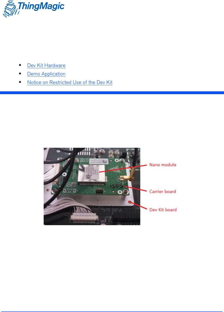 @IhmgMaglc
‘ Dev Kit Hardware
‘ Demo Agghcation
‘ Notrce on Restricted Use of the Dev Krt
Nano module
Carrier board
Dev Kit board
Appendix B: Getting Started - Dev Kit109
A DIVISION OF TRIMBLE
Appendix B: Getting Started - Dev Kit
This appendix provides instructions on the use of the ThingMagic Nano Development Kit:
Dev Kit Hardware
Demo Application
NoticeonRestrictedUseofthe Dev Kit
Dev Kit Hardware
Included Components
With the dev kit, you will receive the following components:
The ThingMagic Nano module soldered onto carrier board
Power/interface developers board
One USB cable
One antenna
One coax cable
One 9V power supply
International power adapter kit
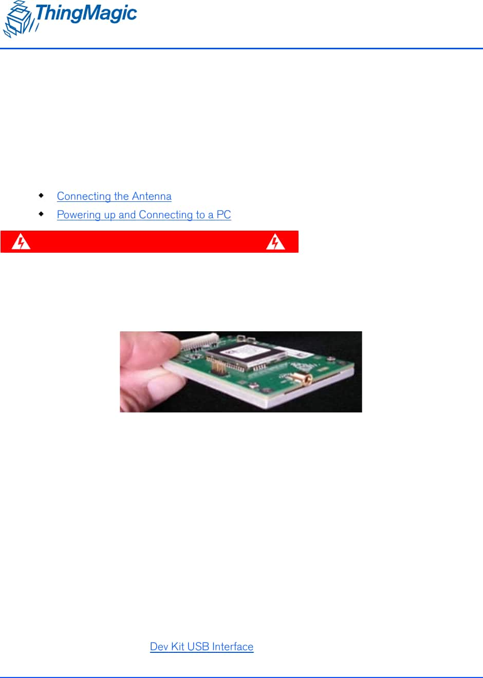 §$7V/‘I'hlngMaglc
‘ Connechng the Antenna
‘ Powenng up and Connecting to a PC
Dev Kit USB \nterface
Dev Kit Hardware
A DIVISION OF TRIMBLE
110 Appendix B: Getting Started - Dev Kit
Sample tags
One QuickStart Guide- Details on which documents and software to download to get
up and running quickly, along with details on how to register for and contact support.
Setting up the Dev Kit
When setting up the Dev Kit, use the following procedures:
ConnectingtheAntenna
Poweringupand Connectingto a PC
WARNING!
Never mount the carrier board so that it is resting flat against the metal
plate of the Dev Kit mainboard unless a heat sinkhas been attached to
the bottom of the Carrier Board as shown in this picture:
Connecting the Antenna
ThingMagic supplies one antenna that can read tags from 3 meters away with most of the
provided tags. The antenna is monstatic. Use the following procedure to connect the
antenna to the Dev Kit.
1. Connect one end of the coax cable to the antenna.
2. Connect the other end of the cable to the antenna port 1 connector on the Dev Kit.
Powering up and Connecting to a PC
After connecting the antenna you can power up the Dev Kit and establish a host
connection.
1. Connect the USB cable (use only the black connector) from a PC to the developerʼs
kit. There are two Dev Kit USB Interfaceoptions. Use the interface that is labeled
 fifhmgMaglc
Dev Kit Hardware
A DIVISION OF TRIMBLE
Appendix B: Getting Started - Dev Kit111
“USB/RS232”. The one labeled “USB” is not supported by the ThingMagic Nano
module.
2. Plug the power supply into the Dev Kitʼs DC power input connector.
3. The LED next to the DC input jack, labeled DS1, should light up. If it doesnʼt light up
check jumper J17to make sure the jumper is connecting pins 2 and 3
4. Follow the steps based on theDev Kit USB Interfaceused and make note of the COM
port or /dev device file, as appropriate for your operating system the USB interface is
assigned.
5. To start reading tags start theDemoApplication(Universal Reader Assistant).
WARNING!
While the module is powered up, do not touch components. Doing so
may be damage the dev kit and ThingMagic Nano module.
 §$7V/‘I'hlngMaglc
9V Power Source
58 connection ham PC
Dev Kit Hardware
A DIVISION OF TRIMBLE
112 Appendix B: Getting Started - Dev Kit
Dev Kit USB Interface
USB/RS232
The USB interface (connector labeled USB/RS232) closest to the power plug is to the
RS232 interface of the ThingMagic Nano through an FTDI USB to serial converter. The
drivers for it are available at
http://www.ftdichip.com/Drivers/VCP.htm
Please follow the instructions in the installation guide appropriate for your operating
system.
The ThingMagic Nano does not support a USB port directly, so the “USB” port on the Dev
Kit is inoperable.
A COM port should now be assigned to the ThingMagic Nano. If you arenʼt sure what
COM port is assigned you can find it using the Windows Device Manager:
a. Open the Device Manager (located in Control Panel | System).
b. Select the Hardware tab and click Device Manager.
c. Select View | Devices by Type | Ports (COM & LPT) The device appears as USB
Serial Port (COM#).
 @fhmgMaglc
See ThingMagic Nana Digitai
Connector Signal Definition ENABLE Line
lfl'fl
' ‘ ' I‘ The snumowu line wiii
> uno’ i . “ Ium uflthe Nano module
“1 “3°“ "3?; " .i i4wnnemdm Gunter
, ‘ m. “new“- mrmaloperaxlonJe um
001-3: i... ‘ (mined SHUTDOWN lo
{DIG ‘ Gnu
Zola
DI:
Remove :ne 3 us jumpers and me
AUTO_BT jumper. These lines musx be
discunnecud ior me ompmdumon version
oi me Nano module in work moperly.
Dev Kit Hardware
A DIVISION OF TRIMBLE
Appendix B: Getting Started - Dev Kit113
Dev kit Jumpers
J8
Jumpers to connect ThingMagic Nano I/O lines to dev kit. For added safety, you should
remove all 3 jumpers for USB connections and the AUTO_BT connection to the module.
These lines are not supported, but are connected to the ThingMagic Nano module for test
purposes, so should be left unconnected for all applications.
J19
The jumper at J19 that connects SHUTDOWN to ground must be REMOVED. With this
jumper removed, the module is always operational. The AUTO_BOOT switch has no
affect on the ThingMagic Nano.To put the ThingMagic Nano into shutdown mode,
reinstall the jumper at J19 between SHUTDOWN and GND. SeeThingMagic NanoDigital
ConnectorSignalDefinitionfor details on theENABLE Line.
J9
Header for alternate power supply. Make sure DC plug (J1) is not connected if using J9.
J10, J11
Jump pins OUTto GPIO#to connect ThingMagic Nano GPIO lines to output LEDs. Jump
pins INto GPIO#to connect ThingMagic Nano GPIO to corresponding input switches.
 §VWThmgMaglc
e Confwgurmg
GPIO Settmgs
J10 J11
Dev Kit Hardware
A DIVISION OF TRIMBLE
114 Appendix B: Getting Started - Dev Kit
Make sure GPIO lines are correspondingly configured as input or outputs (seeConfiguring
GPIO Settings).
J13, J15
Not used.
J14
Can be used to connect GPIO lines to external circuits. If used jumpers should be
removed from J10, J11.
J16
Jump pins 1 and 2 or 2 and 3 to reset dev kit power supply. Same as using switch SW1
except allows for control by external circuit.
J17
Jump pins 1 and 2 to use the 5V INPUTandGNDinputs to provide power. Jump pins 2
and 3 to use the Dev Kitʼs DC power jack and power brick power.
Dev Kit Schematics
Available upon request from support@thingmagic.com.
 fifhmgMaglc
Demo Application
A DIVISION OF TRIMBLE
Appendix B: Getting Started - Dev Kit115
Demo Application
A demo application which supports multi-protocol reading and writing is provided in the
MercuryAPI SDK package. The executable for this example is included in the MercuryAPI
SDK package under /cs/samples/exe/Universal-Reader-Assistant.exe and is also
available for direct download from rfid.thingmagic.com/dev kit.
Note: The Universal Reader Assistant included in the MercuryAPI SDK may be an older revision
than the one available for standalone download.
See the Readme.txtin /cs/samples/Universal-Reader-Assistant/Universal-Reader-
Assistantfor usage details.
See the MercuryAPI Programming Guidefor details on using the MercuryAPI.
 fifhmgMaglc
Notice on Restricted Use of the Dev Kit
A DIVISION OF TRIMBLE
116 Appendix B: Getting Started - Dev Kit
Notice on Restricted Use of the Dev Kit
The Mercury6e Developers Kit (Dev Kit) is intended for use solely by professional
engineers for the purpose of evaluating the feasibility of applications.
The userʼs evaluation must be limited to use within a laboratory setting. This Dev Kit has
not been certified for use by the FCC in accordance with Part 15 of the FCC regulations,
ETSI, KCC or any other regulatory bodies and may not be sold or given for public use.
Distribution and sale of the Dev Kit is intended solely for use in future development of
devices which may be subject to regional regulatory authorities governing radio emission.
This Dev Kit may not be resold by users for any purpose. Accordingly, operation of the
Dev Kit in the development of future devices is deemed within the discretion of the user
and the user shall have all responsibility for any compliance with any regional regulatory
authority governing radio emission of such development or use, including without
limitation reducing electrical interference to legally acceptable levels. All products
developed by user must be approved by the appropriate regional regulatory authority
governing radio emission prior to marketing or sale of such products and user bears all
responsibility for obtaining the prior appropriate regulatory approval, or approval as
needed from any other authority governing radio emission.
 fifhmgMaglc
‘ E‘ectroStahc Drscharge (ESD) Consrderahons
‘ Variables Affecting Performance
Appendix C: Environmental Considerations117
A DIVISION OF TRIMBLE
Appendix C: Environmental
Considerations
This Appendix details environmental factors that should be considered relating to reader
performance and survivability. Topics include:
ElectroStatic Discharge (ESD) Considerations
Variables Affecting Performance
 §VWThmgMaglc
ElectroStatic Discharge (ESD) Considerations
A DIVISION OF TRIMBLE
118 Appendix C: Environmental Considerations
ElectroStatic Discharge (ESD) Considerations
WARNING!
The ThingMagic Nano antenna port may be susceptible to damage from
Electrostatic Discharge (ESD). Equipment failure can result if the antenna or
communication ports are subjected to ESD. Standard ESD precautions should
be taken during installation to avoid static discharge when handling or making
connections to the ThingMagic Nano reader antenna or communication ports.
Environmental analysis shouldalso be performed to ensure static is not building
up on and around the antennas, possibly causing discharges during operation.
ESD Damage Overview
In ThingMagic Nano-based reader installations where readers have failed without a
known destructive event, ESD has been found to be the most common cause. Failures
due to ESD tend to be in the ThingMagic Nano power amplifier section (PA). PA failures
typically manifest themselves at the software interface in the following ways:
RF operations (read, write, etc.) respond with Assert - 7F01- indicating a a fatal
error. This is typically due to the module not being able to reach the target power
level due to PA damage.
RF operations (read, write, etc.) respond with No Antenna Connected/Detected
even when a known good antenna is attached.
Unexpected Invalid Command errors, indicating command not supported, when that
command had worked just fine shortly before. The reason a command becomes
suddenly not supported is that the reader, in the course of its self protection routines,
has returned to the bootloader to prevent any further damage. This jump to boot
loader caused by power amp damage occurs at the start of any read tag commands.
Ultimately determining that ESD is the root cause of failures is difficult because
confirmation is only possible if the failed components are isolated, taken apart, and
examined under high power microscopy. Often, concluding that ESD was the cause of a
failure is inferred if conditions that could produce ESD are present, anti-ESD precautions
have not been taken, and other possible causes are eliminated.
ESD discharges come with a range of values, and like many things in life there is the
“matter of degree”. For many installations, the ThingMagic Nano has been successfully
deployed and operates happily. For these, there is no failure issue, ESD or otherwise. For
a different installation that with bare ThingMagic Nano, has a failure problem from ESD,
there will be some distribution of ESD intensities occurring. Without knowledge of a limit in
 fifhmgMaglc
ElectroStatic Discharge (ESD) Considerations
A DIVISION OF TRIMBLE
Appendix C: Environmental Considerations119
the statistics of those intensities, there may always be the bigger zap waiting in the wings.
For the bare ThingMagic Nano equipped withthe mitigation methods described below,
there will always be the rouge ESD discharge that exceeds any given mitigation, and
results in failure. Fortunately, many installations will have some upper bound on the value
of ESD events given the geometry of that installation.
Several sequential steps are recommended for a) determining the ESD is the likely cause
of a given group of failures, andb) enhancing the ThingMagic Nanoʼs environment to
eliminate ESD failures. The steps vary depending on the required ThingMagic Nano
output power in any given application.
Identifying ESD as the Cause of Damaged Readers
The following are some suggested methods to determine if ESD is a cause of reader
failures, i.e. ESD diagnostics. Please remember- some of these suggestions have the
negative result experiment problem.
Return failed units for analysis. Analysis should be able to say if it is the power
amplifier that has in fact failed, but wonʼt be able to definitively identify that the cause
is ESD. However, ESD is one of the more common causes of PA failure.
Measure ambient static levels with static meter. AlphaLabs SVM2is such a meter, but
there are others. You may be surprised at the static potentials floating detected.
However, high static doesnʼt necessarily mean discharges, but should be considered
cause for further investigation. High levels that keep changing are highly indicative of
discharges.
Touch some things around the antenna, and operating area. If you feel static
discharges, that qualitatively says quite a bit about what is in front of the antenna.
What actually gets to the ThingMagic Nano is also strongly influenced by the antenna
installation, cabling, and grounding discussed above.
Use the mean operating time statistic before and after one or more of the changes
listed below to quantitatively determine if the change has resulted in an improvement.
Be sure to restart your statistics after the change.
Common Installation Best Practices
The following are common installation best practices which will ensure the readers isnʼt
being unnecessarily exposed to ESD in even low risk environments. These should be
applied to all installations, full power or partial power, ESD or not:
Insure that ThingMagic Nano, reader housing, and antenna ground connection are all
grounded to a common low impedance ground.
 fifhmgMaglc
ElectroStatic Discharge (ESD) Considerations
A DIVISION OF TRIMBLE
120 Appendix C: Environmental Considerations
Verify R-TNC knurled threaded nuts are tight and stay tight. Donʼt use a thread locking
compound that would compromise the grounding connection of the thread to thread
mate. If there is any indication that field vibration might cause the R-TNC to loosen,
apply RTV or other adhesive externally.
Use antenna cables with double-shield outer conductors, or even full metallic shield
semi-rigid cables. ThingMagic specified cables are double shielded and adequate for
most applications. ESD discharge currents flowing on the outer surface of a single
shield coaxial cable have been seen to coupleto the inside of coaxial cables, causing
ESD failure. Avoid RG-58. Prefer RG-223.
Minimize ground loops in coaxial cable runs to antennas. Having the ThingMagic
Nano and antenna bothtied to ground (per item 1) leads to the possibility of ground
currents flowing along antenna cables. The tendency of these currents to flow is
related to the area of the conceptual surface marked out by the antenna cable and
the nearest continuous ground surface. When this conceptual surface has minimum
area, these ground loop current are minimized. Routing antenna cables against
grounded metallic chassis parts helps minimize ground loop currents.
Keep the antenna radome in place. It provides significant ESD protection for the
metallic parts of the antenna, and protects the antenna from performance changes
due to environmental accumulation.
Keep careful track of serial numbers, operating life times, numbers of units operating.
You need this information to know that your mean operating life time is. Only with this
number will you be able to know if you have a failure problem in the first place, ESD
or otherwise. And then after any given change, whether things have improvement or
not. Or if the failures are confined to one instantiation, or distributed across your
population.
Raising the ESD Threshold
For applications where full ThingMagic Nano power is needed for maximum tag read
range and ESD is suspected the following components are recommended additions to the
installation to raise the level of ESD the reader can tolerate:
Select or change to an antenna with all radiating elements grounded for DC. The MTI
MT-262031-T(L,R)H-A is such an antenna. The Laird IF900-SF00 and CAF95956
are not such antennas. The grounding of the antenna elements dissipates static
charge leakage, and provides a high pass characteristic that attenuates discharge
events. (This also makes the antenna compatible with the ThingMagic Nano antenna
detect methods.)
Install a Minicircuits SHP600+ high pass filter in the cable run at the ThingMagic Nano
(or Vega or other finished reader) end. This additional component will reduce
transmit power by 0.4 dB which may affect read range in some critical applications.
However the filter will significantly attenuate discharges and improve the ThingMagic
Nano ESD survival level.
 fifhmgMaglc
Note
ElectroStatic Discharge (ESD) Considerations
A DIVISION OF TRIMBLE
Appendix C: Environmental Considerations121
Note
The SHP600+ is rated for the full +27dBm (0.5 W) output of the ThingMagic
Nano reader. Caremust be taken if it is operated at higher RF input levels at
high temperatures.
90 V Lightning Arrestors, such as the Terrawave Solutions Model TW-LP-RPTNC-P-
BHJ have been shown to be effective in suppressing ESD. This model contains a gas
discharge tube which must be replaced periodically.
Install a Diode Clamp* circuit immediately outboard from the SHP600 filter. This will
reduce transmit power by an additional 0.4 dB, but in combination with the SHP600
will further improve the ThingMagic Nano ESD survival level. (Needs DC power,
contact support@thingmagic.com for availability.)
Further ESD Protection for Reduced RF Power Applications
In addition to the protective measures recommended above, for applications where
reduced ThingMagic Nano RF power is acceptable and ESD is suspected the following
protective measures can also be applied:
Install a half watt attenuator with a decibel value of +27 dBm minus the dBm value
needed for tag power up. Then run the reader at +27 dBm instead of reduced
transmit power. This will attenuate inbound ESD pulses by the installed decibel
value, while keeping the tag operation generally unchanged. Note that the receive
sensitivity will be reduced by this same amount. Position the attenuator as close to
the ThingMagic Nano as feasible.
As described above add the SHP600 filter immediately adjacent to the attenuator, on
the antenna side.
Add Diode Clamp, ifrequired, adjacent to the SHP600, on the antenna side.
 fifhmgMaglc
Envxronmenta‘
Tag Consxderations
Mumg‘e Readers
Variables Affecting Performance
A DIVISION OF TRIMBLE
122 Appendix C: Environmental Considerations
Variables Affecting Performance
Reader performance may be affected by the following variables, depending on the site
where your Reader is being deployed:
Environmental
Tag Considerations
Multiple Readers
Environmental
Reader performance may be affected by the following environmental conditions:
Metal surfaces such as desks, filing cabinets, bookshelves, and wastebaskets
may enhance or degrade Reader performance.
Antennas should be mounted far away from metal surfaces that may adversely
affect the system performance.
Devices that operate at 900 MHz, such as cordless phones and wireless LANs,
can degrade Reader performance. The Reader may also adversely affect the
performance of these 900 MHz devices.
Moving machinery can interfere the Reader performance. Test Reader
performance with moving machinery turned off.
Fluorescent lighting fixtures are a source of strong electromagnetic interference
and if possible should be replaced. If fluorescent lights cannot be replaced, then
keep the Reader cables and antennas away from them.
Coaxial cables leading from the Reader to antennas can be a strong source of
electromagnetic radiation. These cables should be laid flat and not coiled up.
Tag Considerations
There are several variables associated with tags that can affect Reader performance:
Application Surface: Some materials, including metal and moisture, interfere with
tag performance. Tags applied to items madefrom or containing these materials
may not perform as expected.
 fifhmgMaglc
Variables Affecting Performance
A DIVISION OF TRIMBLE
Appendix C: Environmental Considerations123
Tag Orientation: Most tags have folded dipole antennas. They read well when
facing the antenna and when their long edge is oriented toward the antenna, but
very poorly when their short edge is oriented toward the antenna.
Tag Model:Many tag models are available. Each model has its own
performance characteristics.
Antenna Considerations
Use a circularly polarized antenna. Linear antennas can only be used if the tag
orientation to the antenna is consistent, or if not always in the ideal orientation, the
antenna or tag can be rotated for best reading.
Use an antenna whose design naturally presents a short to DC. This will help
eliminate ESD issues.
Use an antenna with a return loss of 17 dB or greater (1.33 VSWR) in the
transmission band of the region the module is using.
Use an outdoor-rated antenna if there is a chance that water or dust could get into the
antenna and change its RF characteristics.
Ensure that the antenna is mounted such that personnel do not stand in the radiation
beam of the antenna unless they are more than 21 cm away from the face of the
antenna (to adhere to FCC limits for long term exposure). If the application calls for
personnel to work in the antenna beam and they will be less than 21 cm from the face
of the antenna, the Nano power should be reduced or a lower gain antenna must be
used (21 cm assumes a 27 dBm power level into an 8.15 dBi antenna).
Multiple Readers
The Reader adversely affect performance of 900 MHz devices. These devices also may
degrade performance of the Reader.
Antennas on other Readers operating in close proximity may interfere with one
another, thus degrading performance of the Readers.
Interference from other antennas may be eliminated or reduced by using either
one or both of the following strategies:
w Affected antennas may be synchronized by a separate user application using
a time-multiplexing strategy.
w Antenna power can be reduced by reconfiguring the RF Transmit Power
setting for the Reader.
 fifhmgMaglc
Note
Variables Affecting Performance
A DIVISION OF TRIMBLE
124 Appendix C: Environmental Considerations
Note
Performance tests conducted under typical operating conditions at your site are
recommended to help you optimize system performance.


 被折叠的 条评论
为什么被折叠?
被折叠的 条评论
为什么被折叠?
 到【灌水乐园】发言


