


静态路由介绍:<?xml:namespace prefix = o ns = "urn:schemas-microsoft-com:office:office" />
转发数据包是路由器的最主要功能。路由器转发数据包时需要查找路由表,管理员可以通过手工的方法在路由器中直接配置路由表,这就是静态路由。虽然静态路由不适合于在大的网络中使用,但是由于静态路由简单、路由器负载小、可控性强等原因,在许多场合中还经常被使用。
路由器在转发数据时,要先在路由表(routing table)中查找相应的路由。路由器有这么三种途径建立路由:
(1) 直连网络:路由器自动添加和自己直接连接的网络的路由
(2) 静态路由:管理员手动输入到路由器的路由
(3) 动态路由:由路由协议(routing protocol)动态建立的路由
静态路由的缺点是不能动态反映网络拓扑,当网络拓扑发生变化时,管理员就必须手工改变路由表;然而静态路不会占用路由器太多的CPU 和RAM 资源,也不占用线路的带宽。如果出于安全的考虑想隐藏网络的某些部分或者管理员想控制数据转发路径,也会使用静态路由。在一个小而简单的网络中,也常使用静态路由,因为配置静态路由会更为简捷。
配置静态路由的命令为“ip route”,命令的格式如下:
ip route
目的网络掩码 { 网关地址 | 接口 }
默认路由的介绍:
所谓的默认路由,是指路由器在路由表中如果找不到到达目的网络的具体路由时,最后会采用的路由。默认路由通常会在存根网络(Stub network,即只有一个出口的网络)中使用。命令为:
ip route <?xml:namespace prefix = st1 ns = "urn:schemas-microsoft-com:office:smarttags" />0.0.0.0 0.0.0.0 {
网关地址 | 接口 }
下面通过一个实验,来了解静态路由及默认路由的配置:
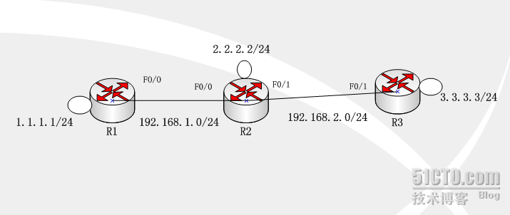
拓扑图如下:
操作步骤:
静态路由的配置
:
我们要使得1.1.1.0/24、2.2.2.0/24、3.3.3.0/24 网络之间能够互相通信。
(1) 步骤1:在各路由器上配置IP 地址、保证直连链路的连通性
R1(config)#int loopback0
R1(config-if)#ip address 1.1.1.1 255.255.255.0
R1(config)#int f0/0
R1(config-if)#ip address 192.168.1.1 255.255.255.0
R1(config-if)#no shutdown
R2(config)#int loopback0
R2(config-if)#ip address 2.2.2.2 255.255.255.0
R2(config)#int f0/0
R2(config-if)#ip address 192.168.1.2 255.255.255.0
R2(config-if)#no shutdown
R2(config)#int f0/1
R2(config-if)#ip address 192.168.2.1 255.255.255.0
R2(config-if)#no shutdown
R3(config)#int loopback0
R3(config-if)#ip address 3.3.3.3 255.255.255.0
R3(config)#int f0/1
R3(config-if)#ip address 192.168.2.2 255.255.255.0
R3(config-if)#no shutdown
(2) 步骤2:R1 上配置静态路由
R1(config)#ip route 2.2.2.0 255.255.255.0 f0/0
//
下一跳为接口形式,f0/0 是点对点的链路,注意应该是R1 上的f0/0 接口
R1(config)#ip route 3.3.3.0 255.255.255.0 192.168.1.2
//
下一跳为IP 地址形式,192.168.1.2 是R2 上的IP 地址
(3) 步骤3:R2 上配置静态路由
R2(config)#ip route 1.1.1.0 255.255.255.0 f0/0
R2(config)#ip route 3.3.3.0 255.255.255.0 f0/1
(4) 步骤4:R3 上配置静态路由
R3(config)#ip route 1.1.1.0 255.255.255.0 f0/1
R3(config)#ip route 2.2.2.0 255.255.255.0 f0/1
(5)
分别在R1,R2,R3上查看路由表
R1#show ip route
Codes: C - connected, S - static, R - RIP, M - mobile, B - BGP
D - EIGRP, EX - EIGRP external, O - OSPF, IA - OSPF inter area
N1 - OSPF NSSA external type 1, N2 - OSPF NSSA external type 2
E1 - OSPF external type 1, E2 - OSPF external type 2
i - IS-IS, su - IS-IS summary, L1 - IS-IS level-1, L2 - IS-IS level-2
ia - IS-IS inter area, * - candidate default, U - per-user static route
o - ODR, P - periodic downloaded static route
Gateway of last resort is not set
1.0.0.0/24 is subnetted, 1 subnets
C 1.1.1.0 is directly connected, Loopback0
2.0.0.0/24 is subnetted, 1 subnets
S 2.2.2.0 is directly connected, Ethernet0/0
3.0.0.0/24 is subnetted, 1 subnets
S 3.3.3.0 [1/0] via 192.168.1.2
C 192.168.1.0/24 is directly connected, Ethernet0/0
R2#show ip route
Codes: C - connected, S - static, R - RIP, M - mobile, B - BGP
D - EIGRP, EX - EIGRP external, O - OSPF, IA - OSPF inter area
N1 - OSPF NSSA external type 1, N2 - OSPF NSSA external type 2
E1 - OSPF external type 1, E2 - OSPF external type 2
i - IS-IS, su - IS-IS summary, L1 - IS-IS level-1, L2 - IS-IS level-2
ia - IS-IS inter area, * - candidate default, U - per-user static route
o - ODR, P - periodic downloaded static route
Gateway of last resort is not set
1.0.0.0/24 is subnetted, 1 subnets
S 1.1.1.0 is directly connected, Ethernet0/0
2.0.0.0/24 is subnetted, 1 subnets
C 2.2.2.0 is directly connected, Loopback0
3.0.0.0/24 is subnetted, 1 subnets
S 3.3.3.0 is directly connected, Ethernet0/1
C 192.168.1.0/24 is directly connected, Ethernet0/0
C 192.168.2.0/24 is directly connected, Ethernet0/1
R3#show ip route
Codes: C - connected, S - static, R - RIP, M - mobile, B - BGP
D - EIGRP, EX - EIGRP external, O - OSPF, IA - OSPF inter area
N1 - OSPF NSSA external type 1, N2 - OSPF NSSA external type 2
E1 - OSPF external type 1, E2 - OSPF external type 2
i - IS-IS, su - IS-IS summary, L1 - IS-IS level-1, L2 - IS-IS level-2
ia - IS-IS inter area, * - candidate default, U - per-user static route
o - ODR, P - periodic downloaded static route
Gateway of last resort is not set
1.0.0.0/24 is subnetted, 1 subnets
S 1.1.1.0 is directly connected, Ethernet0/1
2.0.0.0/24 is subnetted, 1 subnets
S 2.2.2.0 is directly connected, Ethernet0/1
3.0.0.0/24 is subnetted, 1 subnets
C 3.3.3.0 is directly connected, Loopback0
C 192.168.2.0/24 is directly connected, Ethernet0/1
(2)从各路由器的环回接口ping 其他路由器的环回接口:
R1#ping
//
不带任何参数的ping 命令,允许我们输入更多的参数
Protocol [ip]:
Target IP address: 2.2.2.2 //
目标IP 地址
Repeat count [5]: //
发送的ping 次数
Datagram size [100]: //ping
包的大小
Timeout in seconds [2]: //
超时时间
Extended commands [n]: y //
是否进一步扩展命令
Source address or interface: 1.1.1.1 //
源IP 地址
Type of service [0]:
Set DF bit in IP header? [no]:
Validate reply data? [no]:
Data pattern [0xABCD]:
Loose, Strict, Record, Timestamp, Verbose[none]:
Sweep range of sizes [n]:
Type escape sequence to abort.
Sending 5, 100-byte ICMP Echos to 2.2.2.2, timeout is 2 seconds:
Packet sent with a source address of 1.1.1.1
!!!!!
Success rate is 100 percent (5/5), round-trip min/avg/max = 12/14/16 ms
//
以上说明从R1 的loopback0 可以ping 通R2 上的loopback0。也可以直接使用命令:
R1#ping 2.2.2.2 source loopback 0
Type escape sequence to abort.
Sending 5, 100-byte ICMP Echos to 2.2.2.2, timeout is 2 seconds:
Packet sent with a source address of 1.1.1.1
!!!!!
Success rate is 100 percent (5/5), round-trip min/avg/max = 12/14/16 ms
R2#ping 1.1.1.1 source loopback 0
R2#ping 3.3.3.3 source loopback 0
//
从R2 的loopback0 应该可以ping 通R1 和R3 的loopback0 接口。
R3#ping 1.1.1.1 source loopback 0
R3#ping 2.2.2.2 source loopback 0
//
从R3 的loopback0 也应该可以ping 通R1 和R2 的loopback0 接口。
【提示】虽然从R1 的loopback0 可以ping 通R3 的loopback0,数据需要经过
192.168.2.0/24
网络,但是在R1 上我们并没有添加192.168.2.0/24 的路由。路由器转发数据包完成是根据路由表的,并且数据是一跳一跳地被转发的,就像接力赛似的。从R1的loopback0 口ping R3 的loopback0 口时,IP 数据包的源IP 为1.1.1.1,目的IP 为3.3.3.3。R1 路由器首先查路由表,数据包被发到了R2;R2 路由器也查路由表(3.3.3.0/24 路由),数据包被发到了R3;R3 知道这是直连路由。R3 响应R1 的数据包进行类似的过程。
(3) 从R1 上ping 2.2.2.2、从R1 上ping 3.3.3.3
R1#ping 2.2.2.2
Type escape sequence to abort.
Sending 5, 100-byte ICMP Echos to 2.2.2.2, timeout is 2 seconds:
!!!!!
Success rate is 100 percent (5/5), round-trip min/avg/max = 12/14/16 ms
//
可以ping 通。
R1#ping 3.3.3.3
Type escape sequence to abort.
Sending 5, 100-byte ICMP Echos to 3.3.3.3, timeout is 2 seconds:
.....
Success rate is 0 percent (0/5)
//
以上无法ping 通,原因在于使用ping 命令时,如果不指明源接口,则R1 路由器使用f0/0接口的IP 地址(192.168.1.1)作为IP 数据包的源IP 地址了。R3 上响应R1 的数据包时,数据包是发向192.168.1.1 的,然而由于R3 没有192.168.1.0/24 的路由,数据包无法发送。即:数据包从R1 到了R3 后,无法返回R1。
默认路由的配置:
(1) 步骤1:R1、R3 上删除原有静态路由
R1(config)#no ip route 2.2.2.0 255.255.255.0 f0/0
//
要删除路由,在原有命令前面加no 即可
R1(config)#no ip route 3.3.3.0 255.255.255.0 192.168.12.2
R3(config)#no ip route 1.1.1.0 255.255.255.0 f0/1
R3(config)#no ip route 2.2.2.0 255.255.255.0 f0/1
(2) 步骤2: R1、R3 上配置默认路由
R1(config)#ip route 0.0.0.0 0.0.0.0 f0/0
R3(config)#ip route 0.0.0.0 0.0.0.0 f0/1
验证:
从各路由器的环回口ping 其他路由器的环回口,这样,静态路由和默认路由就做好了。
转载于:https://blog.51cto.com/shani/365181


 4683
4683


 被折叠的 条评论
为什么被折叠?
被折叠的 条评论
为什么被折叠?
 到【灌水乐园】发言


