


【OSPF区域0规定
】
OSPF规定,当配置多个区域时,某个区域必须被定义为区域0,所有的区域通信必须通过区域0,因此所有的区域都应该物理连接到区域0。
【些特殊情况】
- 在OSPF网络设计好之后,有一个新的区域要加入,但该区域物理上不具备连接到区域0的条件
- 另外当区域0发送不连续时,区域0被分割开,就出现了2个区域0
虚拟链路正是为了解决以上特殊情况的,下面做一个实验
实验拓扑
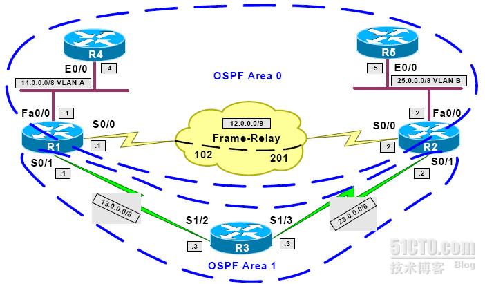
实验要求:按照上图配置网络,并保证在R1与R2链路断开时,R4任然可以ping通R5
实验分析:我们知道R1与R2断开后网络中就会出现两个区域0,此时违反了OSPF的规定,两个区域0之间无法进行信息共享
解决办法:虚链路
配置方法
R1:
interface FastEthernet0/0
ip address 14.0.0.1 255.0.0.0
!
interface Serial0/0
ip address 12.0.0.1 255.0.0.0
encapsulation frame-relay
ip ospf network point-to-point
frame-relay map ip 12.0.0.2 102 broadcast
!
interface Serial0/1
ip address 13.0.0.1 255.0.0.0
!
router ospf 1
router-id 14.0.0.1
area 1 virtual-link 25.0.0.2
network 12.0.0.1 0.0.0.0 area 0
network 13.0.0.1 0.0.0.0 area 1
network 14.0.0.1 0.0.0.0 area 0
R2:
interface FastEthernet0/0
ip address 25.0.0.2 255.0.0.0
!
interface Serial0/0
ip address 12.0.0.2 255.0.0.0
encapsulation frame-relay
ip ospf network point-to-point
frame-relay map ip 12.0.0.1 201 broadcast
!
interface Serial0/1
ip address 23.0.0.2 255.0.0.0
!
router ospf 1
router-id 25.0.0.2
area 1 virtual-link 14.0.0.1
network 12.0.0.2 0.0.0.0 area 0
network 23.0.0.2 0.0.0.0 area 1
network 25.0.0.2 0.0.0.0 area 0
R3:
interface Ethernet0/0
ip address 3.0.0.3 255.0.0.0
!
interface Serial1/2
ip address 13.0.0.3 255.0.0.0
clock rate 64000
!
interface Serial1/3
ip address 23.0.0.3 255.0.0.0
clock rate 64000
!
router ospf 1
network 3.0.0.3 0.0.0.0 area 1
network 13.0.0.3 0.0.0.0 area 1
network 23.0.0.3 0.0.0.0 area 1
R4:
interface Ethernet0/0
ip address 14.0.0.4 255.0.0.0
!
router ospf 1
network 14.0.0.4 0.0.0.0 area 0
R5:
interface Ethernet0/0
ip address 25.0.0.5 255.0.0.0
!
router ospf 1
network 25.0.0.5 0.0.0.0 area 0
未配置虚链路之前
--------------------------------------------------------------------->>
R1#conf t
Enter configuration commands, one per line. End with CNTL/Z.
R1(config)#interface serial0/0
R1(config-if)#shut
R4#show ip route ospf
O IA 23.0.0.0/8 [110/855] via 14.0.0.1, 00:00:42, Ethernet0/0
O IA 13.0.0.0/8 [110/74] via 14.0.0.1, 00:00:42, Ethernet0/0
R5#show ip route ospf
O IA 23.0.0.0/8 [110/74] via 25.0.0.2, 00:00:10, Ethernet0/0
O IA 13.0.0.0/8 [110/855] via 25.0.0.2, 00:00:10, Ethernet0/0
配置虚链路之后
----------------------------------------------------------------------------->>
R1#show ip ospf virtual-links
Virtual Link OSPF_VL2 to router 25.0.0.2 is up
Run as demand circuit
DoNotAge LSA allowed.
Transit area 1, via interface Serial0/1, Cost of using 845
Transmit Delay is 1 sec, State POINT_TO_POINT,
Timer intervals configured, Hello 10, Dead 40, Wait 40, Retransmit 5
Hello due in 00:00:07
Adjacency State FULL (Hello suppressed)
Index 2/3, retransmission queue length 0, number of retransmission 1
First 0x0(0)/0x0(0) Next 0x0(0)/0x0(0)
Last retransmission scan length is 1, maximum is 1
Last retransmission scan time is 0 msec, maximum is 0 msec
R2#show ip ospf virtual-links
Virtual Link OSPF_VL2 to router 14.0.0.1 is up
Run as demand circuit
DoNotAge LSA allowed.
Transit area 1, via interface Serial0/1, Cost of using 845
Transmit Delay is 1 sec, State POINT_TO_POINT,
Timer intervals configured, Hello 10, Dead 40, Wait 40, Retransmit 5
Hello due in 00:00:00
Adjacency State FULL (Hello suppressed)
Index 2/3, retransmission queue length 0, number of retransmission 1
First 0x0(0)/0x0(0) Next 0x0(0)/0x0(0)
Last retransmission scan length is 1, maximum is 1
Last retransmission scan time is 0 msec, maximum is 0 msec
R4#show ip route ospf
O IA 23.0.0.0/8 [110/855] via 14.0.0.1, 00:00:13, Ethernet0/0
O 25.0.0.0/8 [110/865] via 14.0.0.1, 00:00:13, Ethernet0/0
O 12.0.0.0/8 [110/919] via 14.0.0.1, 00:00:13, Ethernet0/0
O IA 13.0.0.0/8 [110/74] via 14.0.0.1, 00:00:13, Ethernet0/0
R5#show ip route ospf
O IA 23.0.0.0/8 [110/74] via 25.0.0.2, 00:00:31, Ethernet0/0
O 12.0.0.0/8 [110/74] via 25.0.0.2, 00:00:31, Ethernet0/0
O IA 13.0.0.0/8 [110/855] via 25.0.0.2, 00:00:31, Ethernet0/0
O 14.0.0.0/8 [110/865] via 25.0.0.2, 00:00:31, Ethernet0/0
上面的实验为区域0被分割的情况,看下面实验为某个区域没有连接到区域0上的例子
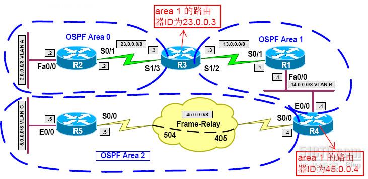
此时我们该如何在R3与R4上进行配置呢?
方法其实和上面类似,在分割区域的两个边界路由器上配置虚链路,虚链路的地址为对端边界路由器的ID
R1:
interface FastEthernet0/0
ip address 14.0.0.1 255.0.0.0
!
interface Serial0/1
ip address 13.0.0.1 255.0.0.0
!
router ospf 1
network 13.0.0.1 0.0.0.0 area 1
network 14.0.0.1 0.0.0.0 area 1
R2:
interface FastEthernet0/0
ip address 2.0.0.2 255.0.0.0
!
interface Serial0/1
ip address 23.0.0.2 255.0.0.0
!
router ospf 1
network 2.0.0.2 0.0.0.0 area 0
network 23.0.0.2 0.0.0.0 area 0
R3:
interface Serial1/2
ip address 13.0.0.3 255.0.0.0
clock rate 64000
!
interface Serial1/3
ip address 23.0.0.3 255.0.0.0
clock rate 64000
!
router ospf 1
area 1 virtual-link 45.0.0.4
network 13.0.0.3 0.0.0.0 area 1
network 23.0.0.3 0.0.0.0 area 0
R4:
interface Ethernet0/0
ip address 14.0.0.4 255.0.0.0
!
interface Serial0/0
ip address 45.0.0.4 255.0.0.0
encapsulation frame-relay
ip ospf network point-to-point
frame-relay map ip 45.0.0.5 405 broadcast
!
router ospf 1
area 1 virtual-link 23.0.0.3
network 14.0.0.4 0.0.0.0 area 1
network 45.0.0.4 0.0.0.0 area 2
R5:
interface Ethernet0/0
ip address 5.0.0.5 255.0.0.0
!
interface Serial0/0
ip address 45.0.0.5 255.0.0.0
encapsulation frame-relay
ip ospf network point-to-point
frame-relay map ip 45.0.0.4 504 broadcast
!
router ospf 1
network 5.0.0.5 0.0.0.0 area 2
network 45.0.0.5 0.0.0.0 area 2
转载于:https://blog.51cto.com/haolun/993187


 439
439


 被折叠的 条评论
为什么被折叠?
被折叠的 条评论
为什么被折叠?
 到【灌水乐园】发言


