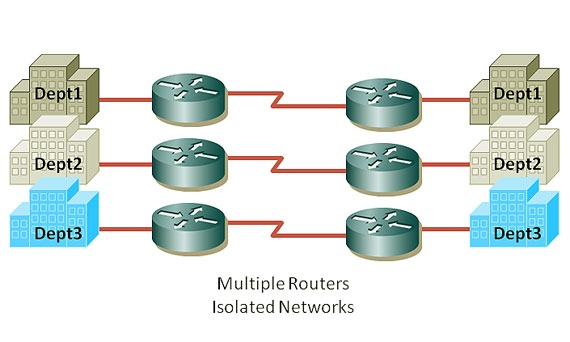
The VRF is “Virtual Routing and Forwarding” to have multiple isolated IP routing tables on a single device. When a route is added to your router all other connected networks will be able to communicate with the new prefix unless you stop them by tools such as access-control lists (ACLs). There are some cases that you might like to have different instances of routing tables for different purposes, such as simple example of guest internet access for guests, It’s an isolated network that might pass some routers but should remain isolated. It’s something like layer 3 VLAN, having two or more isolated “routed” networks. VRF lite is also termed multi-VRF CE, or multi-VRF Customer Edge Device. Imagine two buildings with three networks connected to each other using a WAN circuit, without VRF:

With VRF you can have isolation in a single device – separate routing table for individual interfaces:

While the “VRF Lite” equals to “VRF without the need to run MPLS” in the network, VRF plays a major role in MPLS networks. So whenever we use VRF without MPLS it’s VRF lite. But why we need VRF in MPLS networks? Because we want to route customers networks, they might have overlapped IP addresses. With having multiple VRFs, each customer can have the same address that other customer might like to use without any problem :

Interfaces in a VRF can be either physical, or logical, such as VLAN SVIs, but a Layer 3 interface cannot belong to more than one VRF at any time. So the configuration should be easy! First define each VRF and then allocate desired interface(s) to each VRF. So let’s lab it up, Here’s our plan:

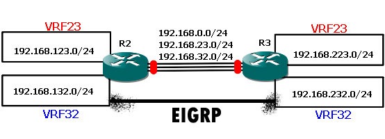
We have R2 and R3 connecting 6 networks together, three networks behind R2 and three network on the right side of the above picture - connected to R3. One each router we create two VRF, (and there’s always a global routing instance so total of three for each side). One global routing table and two VRF – VRF23 and VRF32. We have same VRFs on R3. The requirement is simple, making a connectivity between VRF23 on the right side to the VRF23 on the left side and so on for VRF32.
R2#show ip int br
Interface IP-Address OK?
Ethernet0/0 192.168.0.2 YES
Ethernet0/1 192.168.23.2 YES
Ethernet0/2 192.168.32.2 YES
Ethernet0/3 unassigned YES
Loopback0 2.2.2.2 YES
Loopback23 192.168.123.2 YES
Loopback32 192.168.132.2 YES
And on R3:
R3#sh ip int br
Interface IP-Address OK?
Ethernet0/0 192.168.0.3 YES
Ethernet0/1 192.168.23.3 YES
Ethernet0/2 192.168.32.3 YES
Ethernet0/3 unassigned YES
Loopback0 3.3.3.3 YES
Loopback23 192.168.223.3 YES
Loopback32 192.168.232.3 YES
Yes, I have simulated networks with loopback interfaces… If we don't put interfaces in their appropriate VRF, all route will be exposed to all networks. But we don’t want it! we want to keep’em separated. Fair enough, let’s go to the configuration part:
R2:
ip vrf 23
rd 1:23
!
ip vrf 32
rd 1:32
!
interface Loopback0
ip address 2.2.2.2 255.255.255.0
!
interface Loopback23
ip vrf forwarding 23
ip address 192.168.123.2 255.255.255.0
!
interface Loopback32
ip vrf forwarding 32
ip address 192.168.132.2 255.255.255.0
!
interface Ethernet0/0
ip address 192.168.0.2 255.255.255.0
!
interface Ethernet0/1
ip vrf forwarding 23
ip address 192.168.23.2 255.255.255.0
!
interface Ethernet0/2
ip vrf forwarding 32
ip address 192.168.32.2 255.255.255.0
!
R3:
ip vrf 23
rd 1:23
!
ip vrf 32
rd 1:32
!
interface Loopback0
ip address 3.3.3.3 255.255.255.0
!
interface Loopback23
ip vrf forwarding 23
ip address 192.168.223.3 255.255.255.0
!
interface Loopback32
ip vrf forwarding 32
ip address 192.168.232.3 255.255.255.0
!
interface Ethernet0/0
ip address 192.168.0.3 255.255.255.0
!
interface Ethernet0/1
ip vrf forwarding 23
ip address 192.168.23.3 255.255.255.0
!
interface Ethernet0/2
ip vrf forwarding 32
ip address 192.168.32.3 255.255.255.0
!
So let’s see what we have done by two simple commands:
R2#sh ip vrf
Name Default RD Interfaces
23 1:23 Lo23
Et0/1
32 1:32 Lo32
Et0/2
R2#sh ip route vrf *
2.0.0.0/24 is subnetted, 1 subnets
C 2.2.2.0 is directly connected, Loopback0
C 192.168.0.0/24 is directly connected, Ethernet0/0
Routing Table: 23
C 192.168.123.0/24 is directly connected, Loopback23
C 192.168.23.0/24 is directly connected, Ethernet0/1
Routing Table: 32
C 192.168.132.0/24 is directly connected, Loopback32
C 192.168.32.0/24 is directly connected, Ethernet0/2
Now, we have three different routing tables: global, VRF23 and VRF32 on each router. The Ethernet interface 0/o of R2 is connected to 0/0 of R3 in the global routing table (192.168.0.0/24). Ethernet 0/1 of both devices are connected on another VRF which is 23 and also ethernet0/2 on VRF32. So these two should be able to ping each other inside each VRF, let’s try it now:
R3#ping 192.168.0.2
!!!!!
Success rate is 100 percent (5/5), round-trip min/avg/max = 10/10/10 ms
R3#ping vrf 23 192.168.23.2
!!!!!
Success rate is 100 percent (5/5), round-trip min/avg/max = 10/10/10 ms
R3#ping vrf 32 192.168.32.2
!!!!!
Success rate is 100 percent (5/5), round-trip min/avg/max = 10/10/10 ms
But it’s not enough, these are connected interfaces on both ends, what about networks behind each router, they should have a route to the appropriate network on the other side (loopbacks). We can achieve this requirement just like how we solve it in everyday life, one static route or a using VRF-aware dynamic routing protocol… let’s start with a static route within one VRF.
R2#conf t
R2(config)#ip route vrf 23 192.168.223.3 255.255.255.255 192.168.23.3
R2(config)#end
R2#sh ip route vrf 23
Routing Table: 23
Gateway of last resort is not set
C 192.168.123.0/24 is directly connected, Loopback23
C 192.168.23.0/24 is directly connected, Ethernet0/1
192.168.223.0/32 is subnetted, 1 subnets
S 192.168.223.3 [1/0] via 192.168.23.3
R2#ping vrf 23 192.168.223.3
Type escape sequence to abort.
Sending 5, 100-byte ICMP Echos to 192.168.223.3, timeout is 2 seconds:
!!!!!
Success rate is 100 percent (5/5), round-trip min/avg/max = 10/10/10 ms
Very good… so lets try to run RIP inside VRF23 between R2 and R3… it should discover networks and create a RIP entry in VRF routing table.
VRF-Lite RIP

R2:
router rip
!
address-family ipv4 vrf 23
network 192.168.23.0
network 192.168.123.0
no auto-summary
version 2
exit-address-family
!
R3:
router rip
!
address-family ipv4 vrf 23
network 192.168.23.0
network 192.168.223.0
no auto-summary
version 2
exit-address-family
!
R2#sh ip route vrf 23
Routing Table: 23
Gateway of last resort is not set
C 192.168.123.0/24 is directly connected, Loopback23
C 192.168.23.0/24 is directly connected, Ethernet0/1
R 192.168.223.0/24 [120/1] via 192.168.23.3, 00:00:02, Ethernet0/1
R3#sh ip route vrf 23
Routing Table: 23
Gateway of last resort is not set
R 192.168.123.0/24 [120/1] via 192.168.23.2, 00:00:14, Ethernet0/1
C 192.168.23.0/24 is directly connected, Ethernet0/1
C 192.168.223.0/24 is directly connected, Loopback23
What about EGIRP? Is it VRF-aware? Yes it is…
VRF-Lite EIGRP

R2:
router eigrp 1
auto-summary
!
address-family ipv4 vrf 32
network 192.168.32.0
network 192.168.132.0
no auto-summary
autonomous-system 32
exit-address-family
R2#sh ip eigrp vrf 32 neighbors
IP-EIGRP neighbors for process 32
H Address Interface Hold Uptime SRTT RTO Q Seq
(sec) (ms) Cnt Num
0 192.168.32.3 Et0/2 12 00:12:31 177 1062 0 4
Note: Don’t forget autonomous-system command inside each EIGRP address-family.
VRF-Lite OSPF
Now, it’s time for our popular standard friend – OSPF to come into the picture:

Here’s the plan: Run one OSPF process per VRF.
R2:
router ospf 23 vrf 23
log-adjacency-changes
network 192.168.0.0 0.0.255.255 area 0
!
router ospf 32 vrf 32
log-adjacency-changes
network 192.168.0.0 0.0.255.255 area 0
!
R3:
router ospf 23 vrf 23
log-adjacency-changes
network 192.168.0.0 0.0.255.255 area 0
!
router ospf 32 vrf 32
log-adjacency-changes
network 192.168.0.0 0.0.255.255 area 0
R3#sh ip ospf neighbor
Neighbor ID Pri State Dead Time Address Interface
192.168.132.2 1 FULL/BDR 00:00:38 192.168.32.2 Ethernet0/2
192.168.123.2 1 FULL/BDR 00:00:38 192.168.23.2 Ethernet0/1
R3#sh ip route vrf *
Gateway of last resort is not set
3.0.0.0/24 is subnetted, 1 subnets
C 3.3.3.0 is directly connected, Loopback0
C 192.168.0.0/24 is directly connected, Ethernet0/0
Routing Table: 23
Gateway of last resort is not set
192.168.123.0/32 is subnetted, 1 subnets
O 192.168.123.2 [110/11] via 192.168.23.2, 00:13:53, Ethernet0/1
C 192.168.23.0/24 is directly connected, Ethernet0/1
C 192.168.223.0/24 is directly connected, Loopback23
Routing Table: 32
Gateway of last resort is not set
192.168.132.0/32 is subnetted, 1 subnets
O 192.168.132.2 [110/11] via 192.168.32.2, 00:13:53, Ethernet0/2
C 192.168.232.0/24 is directly connected, Loopback32
C 192.168.32.0/24 is directly connected, Ethernet0/2
VRF-Lite BGP
It’s not MP-BGP (Multi Protocol BGP), it is VRF-aware BGP… each VRF is using its own address family to communicate with corresponding VRF on the other side:

Let’s see final configuration for BGP:
R2:
ip vrf 23
rd 1:23
!
ip vrf 32
rd 1:32
!
interface Loopback0
ip address 3.3.3.3 255.255.255.0
!
interface Loopback23
ip vrf forwarding 23
ip address 192.168.223.3 255.255.255.0
!
interface Loopback32
ip vrf forwarding 32
ip address 192.168.232.3 255.255.255.0
!
interface Ethernet0/0
ip address 192.168.0.3 255.255.255.0
!
interface Ethernet0/1
ip vrf forwarding 23
ip address 192.168.23.3 255.255.255.0
!
interface Ethernet0/2
ip vrf forwarding 32
ip address 192.168.32.3 255.255.255.0
!
router bgp 1
no synchronization
bgp log-neighbor-changes
no auto-summary
!
address-family ipv4 vrf 32
neighbor 192.168.32.2 remote-as 1
neighbor 192.168.32.2 activate
no synchronization
network 192.168.232.0
exit-address-family
!
address-family ipv4 vrf 23
neighbor 192.168.23.2 remote-as 1
neighbor 192.168.23.2 activate
no synchronization
network 192.168.223.0
exit-address-family
!
R3:
ip vrf 23
rd 1:23
!
ip vrf 32
rd 1:32
!
interface Loopback0
ip address 2.2.2.2 255.255.255.0
!
interface Loopback23
ip vrf forwarding 23
ip address 192.168.123.2 255.255.255.0
!
interface Loopback32
ip vrf forwarding 32
ip address 192.168.132.2 255.255.255.0
!
interface Ethernet0/0
ip address 192.168.0.2 255.255.255.0
!
interface Ethernet0/1
ip vrf forwarding 23
ip address 192.168.23.2 255.255.255.0
!
interface Ethernet0/2
ip vrf forwarding 32
ip address 192.168.32.2 255.255.255.0
!
router bgp 1
no synchronization
bgp log-neighbor-changes
no auto-summary
!
address-family ipv4 vrf 32
neighbor 192.168.32.3 remote-as 1
neighbor 192.168.32.3 activate
no synchronization
network 192.168.132.0
exit-address-family
!
address-family ipv4 vrf 23
neighbor 192.168.23.3 remote-as 1
neighbor 192.168.23.3 activate
no synchronization
network 192.168.123.0
exit-address-family
!
R2#show ip bgp ***v4 all
BGP table version is 7, local router ID is 2.2.2.2
Origin codes: i - IGP, e - EGP, ? - incomplete
Network Next Hop Metric LocPrf Weight Path
Route Distinguisher: 1:23 (default for vrf 23)
*> 192.168.123.0 0.0.0.0 0 32768 i
*>i192.168.223.0 192.168.23.3 0 100 0 i
Route Distinguisher: 1:32 (default for vrf 32)
*> 192.168.132.0 0.0.0.0 0 32768 i
*>i192.168.232.0 192.168.32.3 0 100 0 i
转载于:https://blog.51cto.com/hj192837/1020651


 2524
2524

 被折叠的 条评论
为什么被折叠?


