VRRP:
虚拟路由器冗余协议(VRRP)是一种选择协议,它可以把一个虚拟路由器的责任动态分配到局域网上的 VRRP 路由器中的一台。控制虚拟路由器 IP 地址的 VRRP 路由器称为主路由器,它负责转发数据包到这些虚拟 IP 地址。一旦主路由器不可用,这种选择过程就提供了动态的故障转移机制,这就允许虚拟路由器的 IP 地址可以作为终端主机的默认第一跳路由器。使用 VRRP 的好处是有更高的默认路径的可用性而无需在每个终端主机上配置动态路由或路由发现协议。 VRRP 包封装在 IP 包中发送。
VRRP的三种状态模型:
1.初始状态Initialize
2.活动状态Master
3.备份状态Backup
VRRP的选举机制:
虚拟交换机根据配置的优先级的大小选择主交换机,优先级最大的作为主交换机,状态为Master,若优先级相同(如果交换机没有配置优先级,就采用默认值100),则比较接口的主IP地址,主IP地址大的就成为主交换机,由它提供实际的路由服务。其他交换机作为备份交换机,随时监测主交换机的状态。当主交换机正常工作时,它会每隔一段时间发送一个VRRP组播报文,以通知组内的备份交换机,主交换机处于正常工作状态。如果组内的备份交换机长时间没有接收到来自主交换机的VRRP组播报文,则将自己状态转换为Master。当组内有多台备份交换机,将有可能产生多个主交换机。这时每一个主交换机就会比较VRRP报文中的优先级和自己本地的优先级,如果本地的优先级小于VRRP中的优先级,则将自己的状态转换为Backup,否则保持自己的状态不变。通过这样一个过程,就会将优先级最大的交换机选成新的主交换机,完成VRRP的备份功能。
HSRP:
热备份路由协议(HSRP)的设计目标是支持特定情况下 IP 流量失败转移不会引起混乱、并允许主机使用单路由器,以及即使在实际第一跳路由器使用失败的情形下仍能维护路由器间的连通性。换句话说,当源主机不能动态知道第一跳路由器的 IP 地址时,HSRP 协议能够保护第一跳路由器不出故障。
HSRP的工作原理: HSRP协议利用一个优先级方案来决定哪个配置了HSRP协议的路由器成为默认的主动路由器。如果一个路由器的优先级设置的比所有其他路由器的优先级高,则该路由器成为主动路由器。路由器的缺省优先级是100,所以如果只设置一个路由器的优先级高于100,则该路由器将成为主动路由器。通过在设置了HSRP协议的路由器之间广播HSRP优先级,HSRP协议选出当前的主动路由器。当在预先设定的一段时间内主动路由器不能发送hello消息时,优先级最高的备用路由器变为主动路由器。路由器之间的包传输对网络上的所有主机来说都是透明的。
VRRP和HSRP的区别:
VRRP协议的工作机理与CISCO公司的HSRP(Hot Standby Routing Protocol)有许多相似之处。但二者主要的区别是在CISCO的HSRP中,需要单独配置一个IP地址作为虚拟路由器对外体现的地址,这个地址不能是组中任何一个成员的接口地址。
案例一:
实验要求:
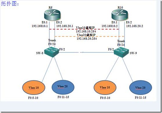
现有两台路由器,两台交换机以及两台测试pc。要求在两台路由器上划分子接口,实现vlan间路由。并配置vrrp(虚拟路由冗余协议),实现两台路由器负载均衡,互相备份。
实验环境:2台Quidway 2600路由器 , 2台Quidway 2000 交换机
拓扑图
配置步骤:
R5
[R5]int eth 0.1 ##进入eth0的子接口1
[R5-Ethernet0.1]vlan-type dot1q vid 10 ## 将子接口封装为dot1q,属于vlan10
[R5-Ethernet0.1]ip add 192.168.10.1 24 ##为该子接口配置ip地址
[R5]int eth 0.2 ##进入eth0的子接口2
[R5-Ethernet0.2]vlan-type dot1q vid 20 ## 将子接口封装为dot1q,属于vlan20
[R5-Ethernet0.2]ip add 192.168.20.1 24 ## 为子接口配置ip地址
[R5]vrrp ping-enable ## 使vlan内的主机可以ping通虚拟ip地址
[R5]int e 0.1## 进入子接口0.1配置虚拟冗余路由协议
[R5-Ethernet0.1]vrrp vrid 10 virtual-ip 192.168.10.254 ##vrrp的编号为10,虚拟ip地址为192.168.10.254
[R5-Ethernet0.1]vrrp vrid 10 priority 120 ##vrrp 10的优先级为120,默认为100
[R5-Ethernet0.1]int e 0.2 ## 进入子接口0.2配置虚拟冗余路由协议
[R5-Ethernet0.2]vrrp vrid 20 virtual-ip 192.168.20.254 ##vrrp的编号为20,虚拟ip地址为192.168.20.254
[R5-Ethernet0.2]vrrp vrid 20 priority 100 ##vrrp 20的优先级为默认100
R10
[R10]interface e0.1 ## 进入e0的子接口0.1
[R10-Ethernet0.1]vlan-type dot1q vid 10 ## 将子接口封装为dot1q,属于vlan10
[R10-Ethernet0.1]ip add 192.168.10.2 24 ##为该子接口配置ip地址
[R10-Ethernet0.1]interface e0.2 ##进入eth0的子接口2
[R10-Ethernet0.2]vlan-type dot1q vid 20 ## 将子接口封装为dot1q,属于vlan20
[R10-Ethernet0.2]ip add 192.168.20.2 24 ## 为子接口配置ip地址
[R10]vrrp ping-enable ## 使vlan内的主机可以ping通虚拟ip地址
[R10]interface e0.1 ## 进入子接口0.2配置虚拟冗余路由协议
[R10-Ethernet0.1]vrrp vrid 10 virtual-ip 192.168.10.254##vrrp的编号为10,虚拟ip地址为192.168.10.254与R5路由器相对应
[R10-Ethernet0.1]vrrp vrid 10 priority 100 ##vrrp 10的优先级为100,默认为100
[R10-Ethernet0.1]interface e0.2## 进入子接口0.2配置虚拟冗余路由协议
[R10-Ethernet0.2]vrrp vrid 20 virtual-ip 192.168.20.254 ##vrrp的编号为20,虚拟ip地址为192.168.20.254
[R10-Ethernet0.2]vrrp vrid 20 priority 120 #vrrp 20的优先级为120,默认100
SW8
[SW8]int e 0/24 ##进入与路由器相连的接口e 0/24
[SW8-Ethernet0/24]port link-type trunk ##将该接口设置为trunk接口
[SW8-Ethernet0/24]port trunk permit vlan all ## 允许所有vlan通过
[SW8]int Ethernet 0/2 ##进入与交换机SW9相连的接口
[SW8-Ethernet0/2]port link-type trunk ##将该接口设置为trunk接口
[SW8-Ethernet0/2]port trunk permit vlan all## 允许所有vlan通过
[SW8]vlan 10 ##创建vlan10
[SW8-vlan10]port Ethernet 0/5 to Ethernet 0/10 ##将接口e 0/5 到 0/10接口加入vlan10
[SW8]vlan 20 ##创建vlan20
[SW8-vlan20]port Ethernet 0/11 to Ethernet 0/15 ##将接口e 0/11 到 0/15接口加入vlan20
SW9
[SW9]vlan 10 ##创建vlan10
[SW9-vlan10]port Ethernet 0/5 to Ethernet 0/10##将接口e 0/5 到 0/10接口加入vlan10
[SW9-vlan10]vlan 20 ##创建vlan20
[SW9-vlan20]port Ethernet 0/11 to Ethernet 0/15##将接口e 0/11 到 0/15接口加入vlan20
[SW9]interface Ethernet 0/24 ##进入与路由器相连的接口e 0/24
[SW9-Ethernet0/24]port link-type trunk ##将该接口设置为trunk接口
[SW9-Ethernet0/24]port trunk permit vlan all ## 允许所有vlan通过
[SW9]interface Ethernet 0/2 ##进入与交换机SW9相连的接口
[SW9-Ethernet0/2]port link-type trunk ##将该接口设置为trunk接口
[SW9-Ethernet0/3]port trunk permit vlan all ## 允许所有vlan通过
测试结果:
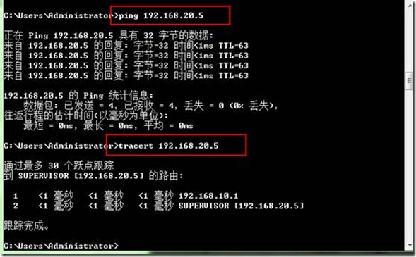
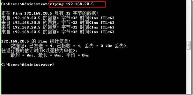
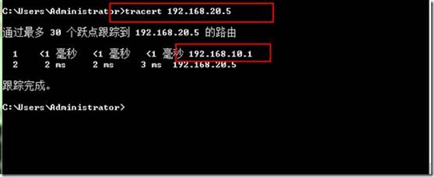
左侧vlan 10主机ping右侧 vlan 20内主机,执行tracert命令,可以发现到达192.168.20.5经过R5 路由器的子接口e0.1
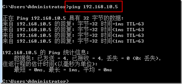
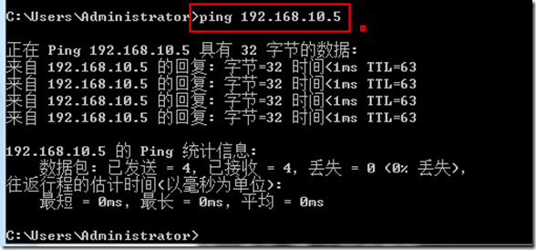
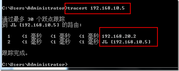
右侧Vlan20 主机ping 左侧 vlan 10主机
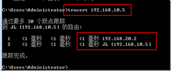
执行tracert命令,可以发现到达192.168.10.5经过R10 路由器的子接口e0.2
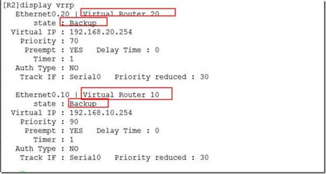
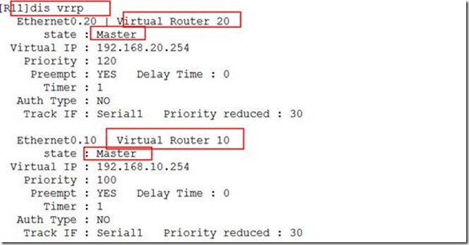
查看R5上的vrrp配置,编号为10的 虚拟路由器为激活状态,20 为备份状态
拔掉R5 路由器与SW8交换机之间的链路
再次跟踪到192.168.20.5,这次是、到达目的地经过路由器R10 的E0.1接口
右侧的vlan20 ping左侧的vlan10
到达10.5经过R10 路由器上的E0.2接口。
查看R10 上的VRRP配置信息,10和20 都为激活状态
案例二:
实验要求:
现有两台路由器,两台测试pc,四台交换机,其中SW1和SW2为核心交换机,SW3和SW4 为接入层交换机,通过单臂路由实现vlan间通信,并在路由器上配置热备份路由器协议(HSRP),交换机上配置生成树协议,以及端口聚合确保冗余。
拓扑图:
配置步骤:
R1
| |
R1(config)#int fa 0/0## 进入该接口,启用该接口,便于配置子接口
R1(config-if)#no shutdown
R1(config)#int fa 0/0.1 ##进入子接口fa0.1
R1(config-subif)#encapsulation dot1Q 10 ## 将子接口封装成802.1q,属于vlan10
R1(config-subif)#ip address 192.168.10.1 255.255.255.0##为子接口配置ip地址
R1(config-subif)#no shutdown
R1(config-subif)#standby 1 ip 192.168.10.254 ##新建备份组1,虚拟ip为192.168.10.254
R1(config-subif)#standby 1 priority 120 ##备份组1的优先级为120
R1(config-subif)#standby 1 preempt ##配置抢占模式
R1(config)#int fa 0/0.2 ##进入子接口fa0.2
R1(config-subif)#encapsulation dot1Q 20 ## 将子接口封装成802.1q,属于vlan20
R1(config-subif)#ip add 192.168.20.1 255.255.255.0 ##为子接口配置ip地址
R1(config-subif)#no shutdown
R1(config-subif)#standby 2 ip 192.168.20.254 #新建备份组2,虚拟ip为192.168.20.254
R1(config-subif)#standby 2 priority 100 ##备份组2的优先级为100
R1(config-subif)#standby 2 preempt ##配置抢占模式
R1#show running-config
Building configuration...
Current configuration : 812 bytes
!
version 12.4
service timestamps debug datetime msec
service timestamps log datetime msec
no service password-encryption
!
hostname R1
!
boot-start-marker
boot-end-marker
!
!
no aaa new-model
memory-size iomem 5
!
interface FastEthernet0/0
no ip address
duplex auto
speed auto
!
interface FastEthernet0/0.1
encapsulation dot1Q 10
ip address 192.168.10.1 255.255.255.0
standby 1 ip 192.168.10.254
standby 1 priority 120
standby 1 preempt
!
interface FastEthernet0/0.2
encapsulation dot1Q 20
ip address 192.168.20.1 255.255.255.0
standby 2 ip 192.168.20.254
standby 2 preempt
!
ip http server
no ip http secure-server
control-plane
line con 0
exec-timeout 0 0
logging synchronous
line aux 0
line vty 0 4
!
!
end
R2
R2(config)#int fa 0/0 ## 进入该接口,启用该接口,便于配置子接口
R2(config-if)#no shutdown
R2(config)#int fa 0/0.1 ##进入子接口fa0.1
R2(config-subif)#encapsulation dot1Q 10 ## 将子接口封装成802.1q,属于vlan10
R2(config-subif)#ip address 192.168.10.2 255.255.255.0 ##为子接口配置ip地址
R2(config-subif)#no shut
R2(config-subif)#standby 1 ip 192.168.10.254##新建备份组1,虚拟ip为192.168.10.254(与)
R2(config-subif)#standby 1 priority 100 ##备份组1的优先级为100
R2(config-subif)#standby 1 preempt ##配置抢占模式
R2(config)#int fa 0/0.2##进入子接口fa0.2
R2(config-subif)#encapsulation dot1Q 20## 将子接口封装成802.1q,属于vlan20
R2(config-subif)#ip address 192.168.20.2 255.255.255.0 ##为子接口配置ip地址
R2(config-subif)#no shut
R2(config-subif)#standby 2 ip 192.168.20.254 #新建备份组2,虚拟ip为192.168.20.254
R2(config-subif)#standby 2 priority 120 ##备份组2的优先级为120
R2(config-subif)#standby 2 preempt ##配置抢占模式
R2#show running-config
Building configuration...
Current configuration : 812 bytes
!
version 12.4
service timestamps debug datetime msec
service timestamps log datetime msec
no service password-encryption
!
hostname R2
!
boot-start-marker
boot-end-marker
!
!
no aaa new-model
memory-size iomem 5
!
interface FastEthernet0/0
no ip address
duplex auto
speed auto
!
interface FastEthernet0/0.1
encapsulation dot1Q 10
ip address 192.168.10.2 255.255.255.0
standby 1 ip 192.168.10.254
standby 1 preempt
!
interface FastEthernet0/0.2
encapsulation dot1Q 20
ip address 192.168.20.2 255.255.255.0
standby 2 ip 192.168.20.254
standby 2 priority 120
standby 2 preempt
!
ip http server
no ip http secure-server
!
!
!
!
!
control-plane
!
!
!
!
!
!
!
!
!
!
line con 0
exec-timeout 0 0
logging synchronous
line aux 0
line vty 0 4
!
!
end
R3
R3(config)#int fa 0/0
R3(config-if)#ip address 192.168.10.5 255.255.255.0
R3(config-if)#no shutdown
R3(config)#ip route 0.0.0.0 0.0.0.0 192.168.10.254 ##配置默认路由,指向虚拟ip地址
R4
R4(config)#int fa 0/0
R4(config-if)#ip add
R4(config-if)#ip address 192.168.20.5 255.255.255.0
R4(config-if)#no shut
R4(config)#ip route 0.0.0.0 0.0.0.0 192.168.20.254 ##配置默认路由,指向虚拟ip地址
SW1
SW1(config)#interface fastEthernet 0/0 ##与路由器R1相连的接口
SW1(config-if)#switchport mode trunk ##将该接口设置为trunk
SW1(config)#int range fa 0/1 - 2
SW1(config-if-range)#switchport mode trunk ##将fa 0/1 - 2设置为trunk
SW1(config-if-range)#channel-group 1 mode on ##将fa 0/1 - 2设置为聚合端口
SW1(config)#int fa 0/3
SW1(config-if)#switchport mode trunk ##与交换机SW3相连的接口设置为trunk
SW1(config-if)#int fa 0/4 ##与交换机SW4相连的接口设置为trunk
SW1(config-if)#switchport mode trunk
SW1#vlan database ##在交换机中创建vlan数据库
SW1(vlan)#vlan 10
SW1(vlan)#vlan 20
SW1(config)#spanning-tree vlan 10 root primary ##vlan10 中该交换机为根交换机
SW1# show spanning-tree brief
VLAN1
Spanning tree enabled protocol ieee
Root ID Priority 32768
Address cc00.2034.0000
Cost 19
Port 5 (FastEthernet0/4)
Hello Time 2 sec Max Age 20 sec Forward Delay 15 sec
Bridge ID Priority 32768
Address cc00.2834.0000
Hello Time 2 sec Max Age 20 sec Forward Delay 15 sec
Aging Time 300
Interface Designated
Name Port ID Prio Cost Sts Cost Bridge ID Port ID
-------------------- ------- ---- ----- --- ----- -------------------- -------
FastEthernet0/0 128.1 128 19 FWD 19 32768 cc00.2834.0000 128.1
FastEthernet0/3 128.4 128 19 FWD 19 32768 cc00.2834.0000 128.4
FastEthernet0/4 128.5 128 19 FWD 0 32768 cc00.2034.0000 128.5
Port-channel1 129.65 128 12 FWD 19 32768 cc00.2834.0000 129.65
VLAN10
Spanning tree enabled protocol ieee
Root ID Priority 8192
Address cc00.2834.0001
This bridge is the root
Hello Time 2 sec Max Age 20 sec Forward Delay 15 sec
Bridge ID Priority 8192
Address cc00.2834.0001
Hello Time 2 sec Max Age 20 sec Forward Delay 15 sec
Aging Time 300
Interface Designated
Name Port ID Prio Cost Sts Cost Bridge ID Port ID
-------------------- ------- ---- ----- --- ----- -------------------- -------
FastEthernet0/0 128.1 128 19 FWD 0 8192 cc00.2834.0001 128.1
FastEthernet0/3 128.4 128 19 FWD 0 8192 cc00.2834.0001 128.4
FastEthernet0/4 128.5 128 19 FWD 0 8192 cc00.2834.0001 128.5
Port-channel1 129.65 128 12 FWD 0 8192 cc00.2834.0001 129.65
VLAN20
Spanning tree enabled protocol ieee
Root ID Priority 8192
Address cc00.2f94.0002
Cost 12
Port 321 (Port-channel1)
Hello Time 2 sec Max Age 20 sec Forward Delay 15 sec
Bridge ID Priority 32768
Address cc00.2834.0002
Hello Time 2 sec Max Age 20 sec Forward Delay 15 sec
Aging Time 300
Interface Designated
Name Port ID Prio Cost Sts Cost Bridge ID Port ID
-------------------- ------- ---- ----- --- ----- -------------------- -------
FastEthernet0/0 128.1 128 19 FWD 12 32768 cc00.2834.0002 128.1
FastEthernet0/3 128.4 128 19 FWD 12 32768 cc00.2834.0002 128.4
FastEthernet0/4 128.5 128 19 FWD 12 32768 cc00.2834.0002 128.5
Port-channel1 129.65 128 12 FWD 0 8192 cc00.2f94.0002 129.65
SW2
SW2(config)#int fa 0/0 ##与路由器R1相连的接口
SW2(config-if)#switchport mode trunk ##将该接口设置为trunk
SW2(config-if)#int range fa 0/1 - 2
SW2(config-if-range)#switchport mode trunk ##将fa 0/1 - 2设置为trunk
SW2(config-if-range)#channel-group 1 mode on##将fa 0/1 - 2设置为聚合端口
SW2(config)#int fa 0/3
SW2(config-if)#switchport mode trunk ##与交换机SW4相连的接口设置为trunk
SW2(config-if)#int fa 0/4##与交换机SW1相连的接口设置为trunk
SW2(config-if)#switchport mode trunk
SW2#vlan database ##在交换机中创建vlan数据库
SW2(vlan)#vlan 10
SW2(vlan)#vlan 20
SW2(config)#spanning-tree vlan 20 root primary ##vlan20 中该交换机为根交换机
SW2# show spanning-tree brief
VLAN1
Spanning tree enabled protocol ieee
Root ID Priority 32768
Address cc00.2034.0000
Cost 31
Port 321 (Port-channel1)
Hello Time 2 sec Max Age 20 sec Forward Delay 15 sec
Bridge ID Priority 32768
Address cc00.2f94.0000
Hello Time 2 sec Max Age 20 sec Forward Delay 15 sec
Aging Time 300
Interface Designated
Name Port ID Prio Cost Sts Cost Bridge ID Port ID
-------------------- ------- ---- ----- --- ----- -------------------- -------
FastEthernet0/0 128.1 128 19 FWD 31 32768 cc00.2f94.0000 128.1
FastEthernet0/3 128.4 128 19 FWD 31 32768 cc00.2f94.0000 128.4
FastEthernet0/4 128.5 128 19 FWD 31 32768 cc00.2f94.0000 128.5
Port-channel1 129.65 128 12 FWD 19 32768 cc00.2834.0000 129.65
VLAN10
Spanning tree enabled protocol ieee
Root ID Priority 8192
Address cc00.2834.0001
Cost 12
Port 321 (Port-channel1)
Hello Time 2 sec Max Age 20 sec Forward Delay 15 sec
Bridge ID Priority 32768
Address cc00.2f94.0001
Hello Time 2 sec Max Age 20 sec Forward Delay 15 sec
Aging Time 300
Interface Designated
Name Port ID Prio Cost Sts Cost Bridge ID Port ID
-------------------- ------- ---- ----- --- ----- -------------------- -------
FastEthernet0/0 128.1 128 19 FWD 12 32768 cc00.2f94.0001 128.1
FastEthernet0/3 128.4 128 19 FWD 12 32768 cc00.2f94.0001 128.4
FastEthernet0/4 128.5 128 19 FWD 12 32768 cc00.2f94.0001 128.5
Port-channel1 129.65 128 12 FWD 0 8192 cc00.2834.0001 129.65
VLAN20
Spanning tree enabled protocol ieee
Root ID Priority 8192
Address cc00.2f94.0002
This bridge is the root
Hello Time 2 sec Max Age 20 sec Forward Delay 15 sec
Bridge ID Priority 8192
Address cc00.2f94.0002
Hello Time 2 sec Max Age 20 sec Forward Delay 15 sec
Aging Time 300
Interface Designated
Name Port ID Prio Cost Sts Cost Bridge ID Port ID
-------------------- ------- ---- ----- --- ----- -------------------- -------
FastEthernet0/0 128.1 128 19 FWD 0 8192 cc00.2f94.0002 128.1
FastEthernet0/3 128.4 128 19 FWD 0 8192 cc00.2f94.0002 128.4
FastEthernet0/4 128.5 128 19 FWD 0 8192 cc00.2f94.0002 128.5
Port-channel1 129.65 128 12 FWD 0 8192 cc00.2f94.0002 129.65
SW3
SW3(config)#int fa 0/3 ##与SW1交换机相连的接口设置为trunk
SW3(config-if)#switchport mode trunk
SW3(config-if)#int fa 0/4
SW3(config-if)#switchport mode trunk ##与SW2交换机相连的接口设置为trunk
SW3#vlan database ##在交换机中创建vlan数据库
SW3(vlan)#vlan 10
SW3(vlan)#vlan 20
SW3(config)#interface range fa 0/5 - 10 ##将 fa 0/5 - 10 加入vlan10
SW3(config-if-range)#switchport access vlan 10
SW3(config)#interface range fa 0/11 - 15 ##将 fa 0/11 - 15 加入vlan20
SW3(config-if-range)#switchport access vlan 20
SW4
SW4(config)#int fa 0/3 ##与SW2交换机相连的接口设置为trunk
SW4(config-if)#switchport mode trunk
SW4(config-if)#int fa 0/4 ##与SW1交换机相连的接口设置为trunk
SW4(config-if)#switchport mode trunk
SW4#vlan database ##在交换机中创建vlan数据库
SW4(vlan)#vlan 10
SW4(vlan)#vlan 20
SW4(config)#int range fa 0/5 - 10 ##将 fa 0/5 - 10 加入vlan10
SW4(config-if-range)#switchport access vlan 10
SW4(config)#int range fa 0/11 - 15##将 fa 0/11 - 15 加入vlan20
SW4(config-if-range)#switchport access vlan 20
测试结果:
vlan10 内的PC R3 跟踪到达对端vlan20的信息
vlan 20 内的主机router4 跟踪到达对端vlan10 的信息
案例二
实验要求:
现有两台路由器,两台测试pc,四台交换机,其中SW1和SW2为核心交换机,SW3和SW4 为接入层交换机,通过单臂路由实现vlan间通信,并在路由器上配置热备份路由器协议(HSRP),交换机上配置生成树协议,以及端口聚合确保冗余。
拓扑图:
配置步骤:
R1
R1(config)#int fa 0/0## 进入该接口,启用该接口,便于配置子接口
R1(config-if)#no shutdown
R1(config)#int fa 0/0.1 ##进入子接口fa0.1
R1(config-subif)#encapsulation dot1Q 10 ## 将子接口封装成802.1q,属于vlan10
R1(config-subif)#ip address 192.168.10.1 255.255.255.0##为子接口配置ip地址
R1(config-subif)#no shutdown
R1(config-subif)#standby 1 ip 192.168.10.254 ##新建备份组1,虚拟ip为192.168.10.254
R1(config-subif)#standby 1 priority 120 ##备份组1的优先级为120
R1(config-subif)#standby 1 preempt ##配置抢占模式
R1(config)#int fa 0/0.2 ##进入子接口fa0.2
R1(config-subif)#encapsulation dot1Q 20 ## 将子接口封装成802.1q,属于vlan20
R1(config-subif)#ip add 192.168.20.1 255.255.255.0 ##为子接口配置ip地址
R1(config-subif)#no shutdown
R1(config-subif)#standby 2 ip 192.168.20.254 #新建备份组2,虚拟ip为192.168.20.254
R1(config-subif)#standby 2 priority 100 ##备份组2的优先级为100
R1(config-subif)#standby 2 preempt ##配置抢占模式
R1#show running-config
Building configuration...
Current configuration : 812 bytes
!
version 12.4
service timestamps debug datetime msec
service timestamps log datetime msec
no service password-encryption
!
hostname R1
!
boot-start-marker
boot-end-marker
!
!
no aaa new-model
memory-size iomem 5
!
interface FastEthernet0/0
no ip address
duplex auto
speed auto
!
interface FastEthernet0/0.1
encapsulation dot1Q 10
ip address 192.168.10.1 255.255.255.0
standby 1 ip 192.168.10.254
standby 1 priority 120
standby 1 preempt
!
interface FastEthernet0/0.2
encapsulation dot1Q 20
ip address 192.168.20.1 255.255.255.0
standby 2 ip 192.168.20.254
standby 2 preempt
!
ip http server
no ip http secure-server
control-plane
line con 0
exec-timeout 0 0
logging synchronous
line aux 0
line vty 0 4
!
!
end
R2
R2(config)#int fa 0/0 ## 进入该接口,启用该接口,便于配置子接口
R2(config-if)#no shutdown
R2(config)#int fa 0/0.1 ##进入子接口fa0.1
R2(config-subif)#encapsulation dot1Q 10 ## 将子接口封装成802.1q,属于vlan10
R2(config-subif)#ip address 192.168.10.2 255.255.255.0 ##为子接口配置ip地址
R2(config-subif)#no shut
R2(config-subif)#standby 1 ip 192.168.10.254##新建备份组1,虚拟ip为192.168.10.254
R2(config-subif)#standby 1 priority 100 ##备份组1的优先级为100
R2(config-subif)#standby 1 preempt ##配置抢占模式
R2(config)#int fa 0/0.2##进入子接口fa0.2
R2(config-subif)#encapsulation dot1Q 20## 将子接口封装成802.1q,属于vlan20
R2(config-subif)#ip address 192.168.20.2 255.255.255.0 ##为子接口配置ip地址
R2(config-subif)#no shut
R2(config-subif)#standby 2 ip 192.168.20.254 #新建备份组2,虚拟ip为192.168.20.254
R2(config-subif)#standby 2 priority 120 ##备份组2的优先级为120
R2(config-subif)#standby 2 preempt ##配置抢占模式
R2#show running-config
Building configuration...
Current configuration : 812 bytes
!
version 12.4
service timestamps debug datetime msec
service timestamps log datetime msec
no service password-encryption
!
hostname R2
!
boot-start-marker
boot-end-marker
!
!
no aaa new-model
memory-size iomem 5
!
interface FastEthernet0/0
no ip address
duplex auto
speed auto
!
interface FastEthernet0/0.1
encapsulation dot1Q 10
ip address 192.168.10.2 255.255.255.0
standby 1 ip 192.168.10.254
standby 1 preempt
!
interface FastEthernet0/0.2
encapsulation dot1Q 20
ip address 192.168.20.2 255.255.255.0
standby 2 ip 192.168.20.254
standby 2 priority 120
standby 2 preempt
!
ip http server
no ip http secure-server
!
!
!
!
!
control-plane
!
!
!
!
!
!
!
!
!
!
line con 0
exec-timeout 0 0
logging synchronous
line aux 0
line vty 0 4
!
!
end
R3
R3(config)#int fa 0/0
R3(config-if)#ip address 192.168.10.5 255.255.255.0
R3(config-if)#no shutdown
R3(config)#ip route 0.0.0.0 0.0.0.0 192.168.10.254 ##配置默认路由,指向虚拟ip地址
R4
R4(config)#int fa 0/0
R4(config-if)#ip add
R4(config-if)#ip address 192.168.20.5 255.255.255.0
R4(config-if)#no shut
R4(config)#ip route 0.0.0.0 0.0.0.0 192.168.20.254 ##配置默认路由,指向虚拟ip地址
SW1
SW1(config)#interface fastEthernet 0/0 ##与路由器R1相连的接口
SW1(config-if)#switchport mode trunk ##将该接口设置为trunk
SW1(config)#int range fa 0/1 - 2
SW1(config-if-range)#switchport mode trunk ##将fa 0/1 - 2设置为trunk
SW1(config-if-range)#channel-group 1 mode on ##将fa 0/1 - 2设置为聚合端口
SW1(config)#int fa 0/3
SW1(config-if)#switchport mode trunk ##与交换机SW3相连的接口设置为trunk
SW1(config-if)#int fa 0/4 ##与交换机SW4相连的接口设置为trunk
SW1(config-if)#switchport mode trunk
SW1#vlan database ##在交换机中创建vlan数据库
SW1(vlan)#vlan 10
SW1(vlan)#vlan 20
SW1(config)#spanning-tree vlan 10 root primary ##vlan10 中该交换机为根交换机
SW1# show spanning-tree brief
VLAN1
Spanning tree enabled protocol ieee
Root ID Priority 32768
Address cc00.2034.0000
Cost 19
Port 5 (FastEthernet0/4)
Hello Time 2 sec Max Age 20 sec Forward Delay 15 sec
Bridge ID Priority 32768
Address cc00.2834.0000
Hello Time 2 sec Max Age 20 sec Forward Delay 15 sec
Aging Time 300
Interface Designated
Name Port ID Prio Cost Sts Cost Bridge ID Port ID
-------------------- ------- ---- ----- --- ----- -------------------- -------
FastEthernet0/0 128.1 128 19 FWD 19 32768 cc00.2834.0000 128.1
FastEthernet0/3 128.4 128 19 FWD 19 32768 cc00.2834.0000 128.4
FastEthernet0/4 128.5 128 19 FWD 0 32768 cc00.2034.0000 128.5
Port-channel1 129.65 128 12 FWD 19 32768 cc00.2834.0000 129.65
VLAN10
Spanning tree enabled protocol ieee
Root ID Priority 8192
Address cc00.2834.0001
This bridge is the root
Hello Time 2 sec Max Age 20 sec Forward Delay 15 sec
Bridge ID Priority 8192
Address cc00.2834.0001
Hello Time 2 sec Max Age 20 sec Forward Delay 15 sec
Aging Time 300
Interface Designated
Name Port ID Prio Cost Sts Cost Bridge ID Port ID
-------------------- ------- ---- ----- --- ----- -------------------- -------
FastEthernet0/0 128.1 128 19 FWD 0 8192 cc00.2834.0001 128.1
FastEthernet0/3 128.4 128 19 FWD 0 8192 cc00.2834.0001 128.4
FastEthernet0/4 128.5 128 19 FWD 0 8192 cc00.2834.0001 128.5
Port-channel1 129.65 128 12 FWD 0 8192 cc00.2834.0001 129.65
VLAN20
Spanning tree enabled protocol ieee
Root ID Priority 8192
Address cc00.2f94.0002
Cost 12
Port 321 (Port-channel1)
Hello Time 2 sec Max Age 20 sec Forward Delay 15 sec
Bridge ID Priority 32768
Address cc00.2834.0002
Hello Time 2 sec Max Age 20 sec Forward Delay 15 sec
Aging Time 300
Interface Designated
Name Port ID Prio Cost Sts Cost Bridge ID Port ID
-------------------- ------- ---- ----- --- ----- -------------------- -------
FastEthernet0/0 128.1 128 19 FWD 12 32768 cc00.2834.0002 128.1
FastEthernet0/3 128.4 128 19 FWD 12 32768 cc00.2834.0002 128.4
FastEthernet0/4 128.5 128 19 FWD 12 32768 cc00.2834.0002 128.5
Port-channel1 129.65 128 12 FWD 0 8192 cc00.2f94.0002 129.65
SW2
SW2(config)#int fa 0/0 ##与路由器R1相连的接口
SW2(config-if)#switchport mode trunk ##将该接口设置为trunk
SW2(config-if)#int range fa 0/1 - 2
SW2(config-if-range)#switchport mode trunk ##将fa 0/1 - 2设置为trunk
SW2(config-if-range)#channel-group 1 mode on##将fa 0/1 - 2设置为聚合端口
SW2(config)#int fa 0/3
SW2(config-if)#switchport mode trunk ##与交换机SW4相连的接口设置为trunk
SW2(config-if)#int fa 0/4##与交换机SW1相连的接口设置为trunk
SW2(config-if)#switchport mode trunk
SW2#vlan database ##在交换机中创建vlan数据库
SW2(vlan)#vlan 10
SW2(vlan)#vlan 20
SW2(config)#spanning-tree vlan 20 root primary ##vlan20 中该交换机为根交换机
SW2# show spanning-tree brief
VLAN1
Spanning tree enabled protocol ieee
Root ID Priority 32768
Address cc00.2034.0000
Cost 31
Port 321 (Port-channel1)
Hello Time 2 sec Max Age 20 sec Forward Delay 15 sec
Bridge ID Priority 32768
Address cc00.2f94.0000
Hello Time 2 sec Max Age 20 sec Forward Delay 15 sec
Aging Time 300
Interface Designated
Name Port ID Prio Cost Sts Cost Bridge ID Port ID
-------------------- ------- ---- ----- --- ----- -------------------- -------
FastEthernet0/0 128.1 128 19 FWD 31 32768 cc00.2f94.0000 128.1
FastEthernet0/3 128.4 128 19 FWD 31 32768 cc00.2f94.0000 128.4
FastEthernet0/4 128.5 128 19 FWD 31 32768 cc00.2f94.0000 128.5
Port-channel1 129.65 128 12 FWD 19 32768 cc00.2834.0000 129.65
VLAN10
Spanning tree enabled protocol ieee
Root ID Priority 8192
Address cc00.2834.0001
Cost 12
Port 321 (Port-channel1)
Hello Time 2 sec Max Age 20 sec Forward Delay 15 sec
Bridge ID Priority 32768
Address cc00.2f94.0001
Hello Time 2 sec Max Age 20 sec Forward Delay 15 sec
Aging Time 300
Interface Designated
Name Port ID Prio Cost Sts Cost Bridge ID Port ID
-------------------- ------- ---- ----- --- ----- -------------------- -------
FastEthernet0/0 128.1 128 19 FWD 12 32768 cc00.2f94.0001 128.1
FastEthernet0/3 128.4 128 19 FWD 12 32768 cc00.2f94.0001 128.4
FastEthernet0/4 128.5 128 19 FWD 12 32768 cc00.2f94.0001 128.5
Port-channel1 129.65 128 12 FWD 0 8192 cc00.2834.0001 129.65
VLAN20
Spanning tree enabled protocol ieee
Root ID Priority 8192
Address cc00.2f94.0002
This bridge is the root
Hello Time 2 sec Max Age 20 sec Forward Delay 15 sec
Bridge ID Priority 8192
Address cc00.2f94.0002
Hello Time 2 sec Max Age 20 sec Forward Delay 15 sec
Aging Time 300
Interface Designated
Name Port ID Prio Cost Sts Cost Bridge ID Port ID
-------------------- ------- ---- ----- --- ----- -------------------- -------
FastEthernet0/0 128.1 128 19 FWD 0 8192 cc00.2f94.0002 128.1
FastEthernet0/3 128.4 128 19 FWD 0 8192 cc00.2f94.0002 128.4
FastEthernet0/4 128.5 128 19 FWD 0 8192 cc00.2f94.0002 128.5
Port-channel1 129.65 128 12 FWD 0 8192 cc00.2f94.0002 129.65
SW3
SW3(config)#int fa 0/3 ##与SW1交换机相连的接口设置为trunk
SW3(config-if)#switchport mode trunk
SW3(config-if)#int fa 0/4
SW3(config-if)#switchport mode trunk ##与SW2交换机相连的接口设置为trunk
SW3#vlan database ##在交换机中创建vlan数据库
SW3(vlan)#vlan 10
SW3(vlan)#vlan 20
SW3(config)#interface range fa 0/5 - 10 ##将 fa 0/5 - 10 加入vlan10
SW3(config-if-range)#switchport access vlan 10
SW3(config)#interface range fa 0/11 - 15 ##将 fa 0/11 - 15 加入vlan20
SW3(config-if-range)#switchport access vlan 20
SW4
SW4(config)#int fa 0/3 ##与SW2交换机相连的接口设置为trunk
SW4(config-if)#switchport mode trunk
SW4(config-if)#int fa 0/4 ##与SW1交换机相连的接口设置为trunk
SW4(config-if)#switchport mode trunk
SW4#vlan database ##在交换机中创建vlan数据库
SW4(vlan)#vlan 10
SW4(vlan)#vlan 20
SW4(config)#int range fa 0/5 - 10 ##将 fa 0/5 - 10 加入vlan10
SW4(config-if-range)#switchport access vlan 10
SW4(config)#int range fa 0/11 - 15##将 fa 0/11 - 15 加入vlan20
SW4(config-if-range)#switchport access vlan 20
测试结果:
vlan10 内的PC R3 跟踪到达对端vlan20的信息
vlan 20 内的主机router4 跟踪到达对端vlan10 的信息
案例三
实验要求:
有vlan10 ,vlan20 用户,要求通过单臂路由实现vlan间通信,使用vrrp协议,使两个路由器互相备份,并对出口进行监控;两个vlan用户通过nat转换访问外网202.102.224.1.
实验环境:华为路由器quidway2600 3台,华为quidway2000交换机2台
拓扑图:
配置步骤:
R2
[R2]interface ethernet 0.10 ##在e0上划分子接口0.10
[R2-Ethernet0.10]vlan-type dot1q vid 10 ##将子接口打802.1q标签,划分到vlan10
[R2-Ethernet0.10]ip address 192.168.10.1 24 ##子接口的ip地址
[R2-Ethernet0.10]vrrp vrid 10 virtual-ip 192.168.10.254## 在该子接口上运行vrrp协议,并将该子接口划分到编号10的组内,虚拟ip地址为192.168.10.254
[R2-Ethernet0.10]vrrp vrid 10 priority 120### vrid 10的优先级为120
[R2-Ethernet0.10]vrrp vrid 10 preempt-mode## 配置抢占模式
[R2-Ethernet0.10]vrrp vrid 10 track serial 0 reduced 30##监控接口serial0,优先级变化幅度为30
[R2]interface ethernet 0.20 ##在e0上划分子接口0.20
[R2-Ethernet0.20]vlan-type dot1q vid 20 ##将子接口打802.1q标签,划分到vlan20
[R2-Ethernet0.20]ip address 192.168.20.1 24 ##子接口的ip地址
[R2-Ethernet0.20]vrrp vrid 20 virtual-ip 192.168.20.254 ## 在该子接口上运行vrrp协议,并将该子接口划分到编号 20的组内,虚拟ip地址为192.168.20.254
[R2-Ethernet0.20]vrrp vrid 20 priority 100 ### vrid 20的优先级为100
[R2-Ethernet0.20]vrrp vrid 20 preempt-mode ## 配置抢占模式
[R2-Ethernet0.20]vrrp vrid 20 track serial 0 reduced 30##监控接口serial0,优先级变化幅度为30
[R2]interface serial 0 ##配置R2与R14的接口
[R2-Serial0]ip address 192.168.1.2 24##配置R2与R14的接口的ip地址
[R2]acl 2000 ##标准访问控制列表2000,控制哪些主机可以通过nat转换访问外网
[R2-acl-2000]rule permit source any
[R2]interface serial 0 ##将访问控制列表应用到serial0的出口上
[R2-Serial0]nat outbound 2000 interface
[R2]ip route-static 0.0.0.0 0.0.0.0 192.168.1.1 ##配置默认路由
R11
[R11]interface ethernet 0.10##在e0上划分子接口0.10
[R11-Ethernet0.10]vlan-type dot1q vid 10##将子接口打802.1q标签,划分到vlan10
[R11-Ethernet0.10]ip address 192.168.10.2 24##子接口的ip地址
[R11-Ethernet0.10]vrrp vrid 10 virtual-ip 192.168.10.254 ## 在该子接口上运行vrrp协议,并将该子接口划分到编号10的组内,虚拟ip地址为192.168.10.254
[R11-Ethernet0.10]vrrp vrid 10 priority 100### vrid 10的优先级为100
[R11-Ethernet0.10]vrrp vrid 10 preempt-mode## 配置抢占模式
[R11-Ethernet0.10]vrrp vrid 10 track serial 1 reduce 30 ##监控接口serial0,优先级变化幅度为30
[R11]interface ethernet 0.20 ##在e0上划分子接口0.20
[R11-Ethernet0.20]vlan-type dot1q vid 20 ##将子接口打802.1q标签,划分到vlan20
[R11-Ethernet0.20]ip address 192.168.20.2 24 ##子接口的ip地址
[R11-Ethernet0.20]vrrp vrid 20 virtual-ip 192.168.20.254 ## 在该子接口上运行vrrp协议,并将该子接口划分到编号 20的组内,虚拟ip地址为192.168.20.254
[R11-Ethernet0.20]vrrp vrid 20 priority 120 ### vrid 20的优先级为120
[R11-Ethernet0.20]vrrp vrid 20 preempt-mode## 配置抢占模式
[R11-Ethernet0.20]vrrp vrid 20 track serial 1 reduced 30##监控接口serial0,优先级变化幅度为30
[R11]interface serial 1##配置R11与R14的接口
[R11-Serial1]ip address 192.168.2.2 24
[R11]acl 2000 #标准访问控制列表2000,控制哪些主机可以通过nat转换访问外网
[R11-acl-2000]rule permit source any
[R11]interface serial 1##将访问控制列表应用到serial1的出口上
[R11-Serial1]nat outbound 2000 interface
[R11]ip route-static 0.0.0.0 0.0.0.0 192.168.2.1##配置默认路由
SW9
[SW9]gvrp###通用vlan注册协议
[SW9]int Ethernet 0/1
[SW9-Ethernet0/1]port link-type trunk ###将Ethernet 0/1设置成为trunk接口
[SW9-Ethernet0/1]port trunk permit vlan all ## 该trunk接口允许所有vlan通过
[SW9-Ethernet0/1]gvrp ###在接口上运用通用vlan注册协议
[SW9]vlan 10 ###创建vlan10
[SW9-vlan10]port Ethernet 0/5 to Ethernet 0/10 ##将接口0/5 to 0/10缴入vlan10
[SW9]vlan 20 ###创建vlan20
[SW9-vlan20]port Ethernet 0/11 to Ethernet 0/15 ##将接口0/11 to 0/15缴入vlan20
[SW9]interface Ethernet 0/2
[SW9-Ethernet0/2]port link-type trunk ##与R2连接的接口设置为trunk
[SW9-Ethernet0/2]port trunk permit vlan all 允许所有vlan通过
SW12
[SW12]gvrp ###通用vlan注册协议
[SW12]interface Ethernet 0/1
[SW12-Ethernet0/1]port link-type trunk ###将Ethernet 0/1设置成为trunk接口
[SW12-Ethernet0/1]port trunk permit vlan all ## 该trunk接口允许所有vlan通过
[SW12-Ethernet0/1]gvrp ###在接口上运用通用vlan注册协议
[SW12]interface Ethernet 0/2
[SW12-Ethernet0/2]port link-type trunk ##与R11连接的接口设置为trunk
[SW12-Ethernet0/2]port trunk permit vlan all 允许所有vlan通过
[SW12]vlan 10 ###创建vlan10
[SW12-vlan10]port Ethernet 0/5 to Ethernet 0/10 #将接口0/5 to 0/10缴入vlan10
[SW12]vlan 20 ###创建vlan20
[SW12-vlan20]port Ethernet 0/11 to Ethernet 0/15 ##将接口0/11 to 0/15缴入vlan20
SW14
[R14]interface serial 0
[R14-Serial0]ip address 192.168.1.1 24
[R14-Serial0]shutdown
[R14-Serial0]undo shutdown
[R14]interface serial 1
[R14-Serial1]ip address 192.168.2.1 24
[R14-Serial1]shundown
[R14-Serial1]undo shutdown
[R14]interface ethernet 0
[R14-Ethernet0]ip add 202.102.224.1 24
[R14-Ethernet0]loopback
测试结果:
右侧vlan20 内的主机F2 ping 左侧vlan10 内主机
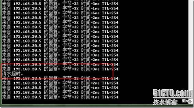
跟踪 到192.168.10.5,路径是先到R11路由器的子接口,说明发送消息是从R11发送。
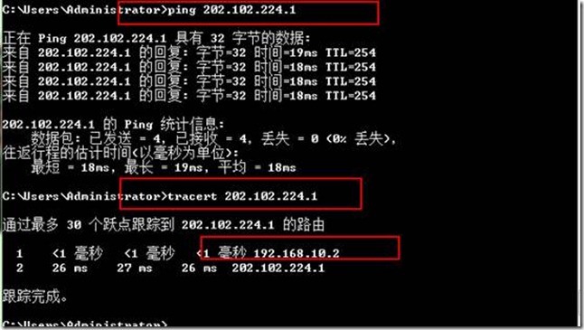
右侧vlan20 能够通过nat转换访问外网
跟踪到202.102.224.1
左侧vlan10 ping 右侧 vlan20
跟踪到192.168.20.5,是从左侧R2路由器的子接口到达。
vlan10 能通过nat转换到达外网 202.102.224.1
跟踪到外网,是从左侧路由器R2出去
断掉R2月SW9 的线路:
跟踪到192.168.20.5 ,路径是先到右侧路由器R11的子接口.
到外网的跟踪
shutdown R2 的接口serial 0
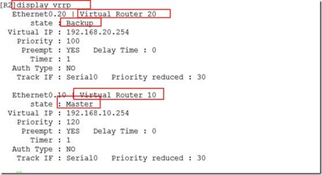
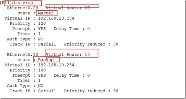
关闭前后对比:
关闭前:
关闭后:
本文出自 “贾亮的博客” 博客,请务必保留此出处http://jialiang10086.blog.51cto.com/4496483/965300
转载于:https://blog.51cto.com/wwysmile/1198303





![clip_p_w_picpath002[4] clip_p_w_picpath002[4]](https://s1.51cto.com/attachment/201208/16/4496483_1345136278o4lU.jpg)
![clip_p_w_picpath004[4] clip_p_w_picpath004[4]](https://s1.51cto.com/attachment/201208/16/4496483_1345136278GjKE.jpg)


![clip_p_w_picpath002[1] clip_p_w_picpath002[1]](https://s1.51cto.com/attachment/201208/19/4496483_1345378451cbrG.jpg)
![clip_p_w_picpath004[1] clip_p_w_picpath004[1]](https://s1.51cto.com/attachment/201208/19/4496483_1345378454tloe.jpg)
![clip_p_w_picpath006[1] clip_p_w_picpath006[1]](https://s1.51cto.com/attachment/201208/19/4496483_1345378455AM2Q.jpg)
![clip_p_w_picpath008[1] clip_p_w_picpath008[1]](https://s1.51cto.com/attachment/201208/19/4496483_1345378458LNSi.jpg)
![clip_p_w_picpath010[1] clip_p_w_picpath010[1]](https://s1.51cto.com/attachment/201208/19/4496483_1345378459SdeA.jpg)
![clip_p_w_picpath012[1] clip_p_w_picpath012[1]](https://s1.51cto.com/attachment/201208/19/4496483_13453784615hqI.jpg)
![clip_p_w_picpath016[1] clip_p_w_picpath016[1]](https://s1.51cto.com/attachment/201208/19/4496483_13453784652Tz6.jpg)




 2849
2849


 被折叠的 条评论
为什么被折叠?


