


第二部分:技术讲解
实验已经做通了,但其中的技术细节还要仔细研究一下。整个m×××的运作以及结构是怎样的呢。下面来说说。
一、 MTI和default MDT
在配置过程中,对PE的配置有两点是需要关注的,一是在loopback0上启用了pim sm,二是在vrf中配置了mdt default 239.100.0.1。
以PE R7为例,在没有配置上面两条命令之前,其pim邻居是这样的:
一种是P网络全局pim邻居
r7#sh ip pim nei
PIM Neighbor Table
Neighbor Interface Uptime/Expires Ver DR
Address Prio/Mode
37.0.0.3 FastEthernet0/0.37 00:52:49/00:01:39 v2 1 / S
47.0.0.4 FastEthernet0/0.47 00:52:49/00:01:40 v2 1 / S
另一种是客户×××内pim邻居
r7#sh ip pim vrf abc nei
PIM Neighbor Table
Neighbor Interface Uptime/Expires Ver DR
Address Prio/Mode
78.0.0.8 FastEthernet0/0.78 00:52:45/00:01:44 v2 1 / DR S
一旦敲入了mdt default 239.100.0.1,R7上马上就会出现信息:
*Mar 1 00:56:52.547: %LINEPROTO-5-UPDOWN: Line protocol on Interface Tunnel0, changed state to up
生成了一个tunnel 0接口,ip 地址使用的是loopback0的地址7.7.7.7。这个tunnel接口叫做MTI(multicast tunnel interface),位于VRF中。
看一下tunnel0的资料:
r7#sh int tun 0
Tunnel0 is up, line protocol is up
Hardware is Tunnel
Interface is unnumbered. Using address of Loopback0 (7.7.7.7)
MTU 1514 bytes, BW 9 Kbit, DLY 500000 usec,
reliability 255/255, txload 1/255, rxload 1/255
Encapsulation TUNNEL, loopback not set
Keepalive not set
Tunnel source 7.7.7.7 (Loopback0), destination 239.100.0.1
Tunnel protocol/transport GRE/IP Multicast, key disabled, sequencing disabled
显示这个tunnel是GRE tunnel,传送ip组播数据。
然后再敲入
r7(config)#int lo0
ip pim sparse-mode
(这个loopback0是MP-iBGP建邻居所用的地址,所以要启用PIM SM,而且它将成为MDT的根)
出现信息如下:
*Mar 1 01:02:33.791: %PIM-5-DRCHG: DR change from neighbor 0.0.0.0 to 7.7.7.7 on interface Loopback0 (vrf default)
*Mar 1 01:02:45.647: %PIM-5-NBRCHG: neighbor 5.5.5.5 UP on interface Tunnel0 (vrf abc)
*Mar 1 01:02:45.975: %PIM-5-NBRCHG: neighbor 2.2.2.2 UP on interface Tunnel0 (vrf abc)
R7跟其他PE建立了pim邻居,使用的是MTI接口,即3个pe以MTI建成了邻居。
r7#sh ip pim vrf abc nei
PIM Neighbor Table
Neighbor Interface Uptime/Expires Ver DR
Address Prio/Mode
78.0.0.8 FastEthernet0/0.78 01:07:08/00:01:36 v2 1 / DR S
2.2.2.2 Tunnel0 00:04:33/00:01:37 v2 1 / S
5.5.5.5 Tunnel0 00:04:33/00:01:38 v2 1 / S
在R2上看:
r2#sh ip pim vrf abc nei
PIM Neighbor Table
Neighbor Interface Uptime/Expires Ver DR
Address Prio/Mode
12.0.0.1 FastEthernet0/0.12 01:09:37/00:01:32 v2 1 / S
7.7.7.7 Tunnel0 00:06:29/00:01:39 v2 1 / DR S
5.5.5.5 Tunnel0 01:08:21/00:01:40 v2 1 / S
显示R7的tunnel0是DR。这是因为3个MTI相当于连接到了1个共享网段上,就像在一个以太网内,所以要选举DR。
MTI很关键,它是客户***的pim和运营商P网络的PIM交互的中介。
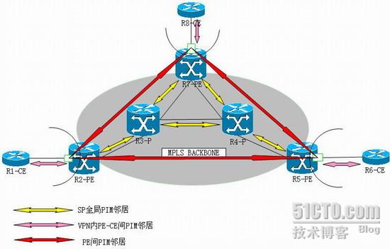
如图,现在整网的pim邻居有这么三种。
我们现在来查看运营商的P路由器R4上的组播路由状态:
r4#sh ip mro
IP Multicast Routing Table
Flags: D - Dense, S - Sparse, B - Bidir Group, s - SSM Group, C - Connected,
L - Local, P - Pruned, R - RP-bit set, F - Register flag,
T - SPT-bit set, J - Join SPT, M - MSDP created entry,
X - Proxy Join Timer Running, A - Candidate for MSDP Advertisement,
U - URD, I - Received Source Specific Host Report, Z - Multicast Tunnel
Y - Joined MDT-data group, y - Sending to MDT-data group
Outgoing interface flags: H - Hardware switched, A - Assert winner
Timers: Uptime/Expires
Interface state: Interface, Next-Hop or VCD, State/Mode
(*, 239.100.0.1), 01:28:04/00:03:03, RP 4.4.4.4, flags: S
Incoming interface: Null, RPF nbr 0.0.0.0
Outgoing interface list:
FastEthernet0/0.47, Forward/Sparse, 00:26:11/00:02:50
FastEthernet0/0.45, Forward/Sparse, 01:28:03/00:03:03
FastEthernet0/0.34, Forward/Sparse, 01:28:04/00:02:56
(2.2.2.2, 239.100.0.1), 01:27:49/00:03:23, flags: T
Incoming interface: FastEthernet0/0.34, RPF nbr 34.0.0.3
Outgoing interface list:
FastEthernet0/0.45, Forward/Sparse, 01:27:49/00:03:03
(5.5.5.5, 239.100.0.1), 01:27:50/00:03:13, flags: T
Incoming interface: FastEthernet0/0.45, RPF nbr 45.0.0.5
Outgoing interface list:
FastEthernet0/0.47, Forward/Sparse, 00:26:11/00:02:50
FastEthernet0/0.34, Forward/Sparse, 01:27:50/00:02:55
(7.7.7.7, 239.100.0.1), 00:31:52/00:03:12, flags: T
Incoming interface: FastEthernet0/0.47, RPF nbr 47.0.0.7
Outgoing interface list:
FastEthernet0/0.45, Forward/Sparse, 00:31:52/00:03:02
(*, 224.0.1.40), 01:29:00/00:03:07, RP 4.4.4.4, flags: SJCL
Incoming interface: Null, RPF nbr 0.0.0.0
Outgoing interface list:
FastEthernet0/0.47, Forward/Sparse, 01:27:40/00:02:38
FastEthernet0/0.45, Forward/Sparse, 01:28:04/00:03:07
FastEthernet0/0.34, Forward/Sparse, 01:28:05/00:03:04
Loopback0, Forward/Sparse, 01:29:00/00:02:01
比前面所见多了4个条目,1个(*,G)和3个(S,G),分别是(*, 239.100.0.1),(2.2.2.2, 239.100.0.1),(5.5.5.5, 239.100.0.1),(7.7.7.7, 239.100.0.1)。这里的G正是前面在vrf中配置的MDT default 239.100.0.1。MDT全称是multicast distribution tree,即组播分发树。配置239.100.0.1这个default MDT虽然是在vrf中,但是是给运营商P网络中的组播路由器来用的。P网络用这个组地址建成了1个全互连的通道供***的组播使用。不管客户***网络内有多少组播源和组地址,运营商网络并不关心,也不需要知道,它只使用这一个缺省的组播分发树来转发客户组播数据。
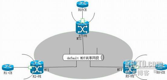
所有的***站点都加入到这棵树中,他们互为发送者和接收者,即既为根(root)又为叶(leaf)。
二、MP-iBGP的组播更新包
PE加入default MDT靠的是MP-iBGP消息,配置了default MDT后他们之间互发MP-iBGP更新,这种更新包与常规***v4的路由更新有所不同。
r7# sh ip bgp v a
BGP table version is 24, local router ID is 7.7.7.7
Status codes: s suppressed, d damped, h history, * valid, > best, i - internal,
r RIB-failure, S Stale
Origin codes: i - IGP, e - EGP, ? - incomplete
Network Next Hop Metric LocPrf Weight Path
Route Distinguisher: 100:1 (default for vrf abc)
*>i1.1.1.1/32 2.2.2.2 2 100 0 ?
*>i6.6.6.6/32 5.5.5.5 2 100 0 ?
*> 8.8.8.8/32 78.0.0.8 2 32768 ?
*>i12.0.0.0/24 2.2.2.2 0 100 0 ?
*>i56.0.0.0/24 5.5.5.5 0 100 0 ?
*> 78.0.0.0/24 0.0.0.0 0 32768 ?
Route Distinguisher: 2:100:1
*>i2.2.2.2/32 2.2.2.2 0 100 0 ?
*>i5.5.5.5/32 5.5.5.5 0 100 0 ?
*> 7.7.7.7/32 0.0.0.0 0 ?
MDT的mp-ibgp更新的RD是2:100:1而不是单播***v4路由更新的100:1。这个2代表RD类型2,区别于单播***v4路由的RD。而且,这种更新携带了一些别的扩展community属性。
r7# sh ip bgp v a 5.5.5.5
BGP routing table entry for 2:100:1:5.5.5.5/32, version 20
Paths: (1 available, best #1, no table, not advertised to EBGP peer)
Not advertised to any peer
Local
5.5.5.5 (metric 3) from 5.5.5.5 (5.5.5.5)
Origin incomplete, metric 0, localpref 100, valid, internal, mdt, no-import, best
Extended Community: RT:100:1 MDT:100:239.100.0.1,
mpls labels in/out nolabel/511
可以看到里面有MDT的信息。
20150316更新:
IOS 15.2已经不用rt来携带mdt,而是使用bgp的mdt地址族来传递给PIM。
router bgp 1
bgplog-neighbor-changes
neighbor peerall peer-group
neighbor peerall remote-as 1
neighbor peerall update-source Loopback0
neighbor 9.9.0.2 peer-group peerall
neighbor 9.9.0.3 peer-group peerall
neighbor 9.9.0.4 peer-group peerall
neighbor 9.9.0.5 peer-group peerall
!
address-family ipv4
neighbor 9.9.0.2 activate
neighbor 9.9.0.3 activate
neighbor 9.9.0.4 activate
neighbor 9.9.0.5 activate
exit-address-family
!
address-family ***v4
neighbor peerall send-community extended
neighbor peerall route-reflector-client
neighbor 9.9.0.2 activate
neighbor 9.9.0.5 activate
exit-address-family
!
address-family ipv4 mdt
neighbor peerall send-community both
neighbor peerall route-reflector-client
neighbor 9.9.0.2 activate 即使对方不支持mdt safi,也要在这里配上激活语句
neighbor 9.9.0.5 activate
查看:
r7#sh ip bgp ipv4 mdt all
BGP table version is 8, local router ID is9.9.0.7
Status codes: s suppressed, d damped, hhistory, * valid, > best, i - internal,
r RIB-failure, S Stale, mmultipath, b backup-path, f RT-Filter,
x best-external, aadditional-path, c RIB-compressed,
Origin codes: i - IGP, e - EGP, ? -incomplete
RPKI validation codes: V valid, I invalid,N Not found
Network Next Hop Metric LocPrf Weight Path
Route Distinguisher: 100:1 (default for vrfabc)
*>i 9.9.0.2/32 9.9.0.2 0 100 0 ?
*>i 9.9.0.5/32 9.9.0.5 0 100 0 ?
*> 9.9.0.7/32 0.0.0.0 0 ?
r7#sh ip bgp ipv4 mdt all 9.9.0.2
BGP routing table entry for100:1:9.9.0.2/32 version 8
Paths: (1 available, best #1, tableIPv4-MDT-BGP-Table)
Advertised to update-groups:
3
RefreshEpoch 1
Local, (Received from a RR-client)
9.9.0.2 from 9.9.0.2 (9.9.0.2)
Origin incomplete, metric 0, localpref 100, valid, internal, best,
MDT group address: 239.0.0.1
推荐在所有参与M×××的路由器上配置MDT SAFI。尽管mdt safi的好处是为了ssm树的构建,在M×××中为PIM-SM配置缺省mdt group时,也必须配置MDT SAFI 。从组播的观点来看,在pim-sm核心中要使M×××工作正常,mdt safi不是必须的。但在某些场景,必须配置新地址族以创建MTI。缺了这句,MTI不会创建,M×××也不工作。
为了向下兼容,要对MDTSAFI下的所有peer启用ext-communities。在纯的支持MDT SAFI的环境,可不显式配置ext-communities。在混合环境下,有的路由器不支持MDT SAFI,就必须配置ext-communities。
三、端到端组播数据包转发分析:
现在以R1为源,R8为接收者分析全程组播包的转发。
1、 R1 ping 238.0.0.1,包到达R2的mvrf
2、 R2的mvrf中的组播路由表如下:
r2#sh ip mro vrf abc
(1.1.1.1, 238.0.0.1), 00:00:08/00:03:21, flags:
Incoming interface: FastEthernet0/0.12, RPF nbr 12.0.0.1
Outgoing interface list:
Tunnel0, Forward/Sparse, 00:00:08/00:03:21
出接口为tunnel0。于是MTI用GRE将组播包封装起来,源地址改为2.2.2.2,目的地址为239.100.0.1。现在要从vrf中出到全局中去了。
r2#sh ip mro
(2.2.2.2, 239.100.0.1), 02:50:31/00:03:14, flags: FTZ
Incoming interface: Loopback0, RPF nbr 0.0.0.0
Outgoing interface list:
FastEthernet0/0.23, Forward/Sparse, 02:50:31/00:02:50
根据全局组播路由表,出接口为f0/0.23,送出。R3收到。
3、 R3的全局组播路由表如下
r3#sh ip mro
(2.2.2.2, 239.100.0.1), 02:49:13/00:03:02, flags: T
Incoming interface: FastEthernet0/0.23, RPF nbr 23.0.0.2
Outgoing interface list:
FastEthernet0/0.37, Forward/Sparse, 01:47:35/00:03:04
FastEthernet0/0.34, Forward/Sparse, 02:49:13/00:03:28, A
将包复制两份,分别从f0/0.37和f0/0.34送出,R7和R4收到。
4、R7的全局组播路由表如下
r7#sh ip mro
(2.2.2.2, 239.100.0.1), 01:59:49/00:02:57, flags: JTZ
Incoming interface: FastEthernet0/0.37, RPF nbr 37.0.0.3
Outgoing interface list:
MVRF abc, Forward/Sparse, 01:54:09/00:02:57
出接口为mvrf,于是被送入vrf中。
R7的mvrf的组播路由表如下:
r7#sh ip mro vrf abc
(1.1.1.1, 238.0.0.1), 00:01:38/00:01:51, flags:
Incoming interface: Tunnel0, RPF nbr 2.2.2.2
Outgoing interface list:
FastEthernet0/0.78, Forward/Sparse, 00:01:38/00:03:19
出接口为f0/0.78,送出。R8收到,到终点站。
5、另一路R4收到的包会被R5抛弃,因为R5的mvrf中无出口。
r5#sh ip mro vrf abc
(*, 238.0.0.1), 00:00:15/00:02:47, RP 1.1.1.1, flags: SP
Incoming interface: Tunnel0, RPF nbr 2.2.2.2
Outgoing interface list: Null
转载于:https://blog.51cto.com/jetko/58379


 320
320


 被折叠的 条评论
为什么被折叠?
被折叠的 条评论
为什么被折叠?
 到【灌水乐园】发言


