


Redundancy ×××,就是冗余×××,与前面讲到的HA ×××差不多,唯一的区别就是多了一个HSRP的应用。
下面的小实验简单演示redundancy ×××的配置示例和一些需要注意的地方。
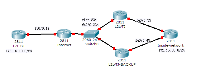
拓扑:
说明:
1. L2L-BJ模拟一个远端(北京)的L2L设备,L2L-TJ模拟对端(天津)的L2L设备,2L2-TJ-BACKUP作为一条备份的L2L路由器。
2. Internet模拟ISP网络,Inside-network模拟TJ背后的用户网络(172.16.50.0/24),北京背后的网络为172.16.10.0/24。
3. Internet路由器与L2L-TJ和L2L-TJ-BACKUP运行在同一个VLAN中以实施HSRP。
4. L2L-TJ,inside-network,L2L-TJ-BACKUP间运行OSPF。
基本配置
L2L-BJ:
!
hostname L2L-BJ
!
ip cef
!
interface Loopback0
ip address 172.16.10.1 255.255.255.0
!
interface FastEthernet0/0
no ip address
duplex auto
speed auto
!
interface FastEthernet0/0.12
encapsulation dot1Q 12
ip address 12.1.1.1 255.255.255.0
!
ip route 0.0.0.0 0.0.0.0 FastEthernet0/0.12 12.1.1.2
!
Internet:
!
hostname Internet
!
ip cef
!
interface FastEthernet0/0
no ip address
duplex auto
speed auto
!
interface FastEthernet0/0.12
encapsulation dot1Q 12
ip address 12.1.1.2 255.255.255.0
!
interface FastEthernet0/0.234
encapsulation dot1Q 234
ip address 10.1.1.2 255.255.255.0
!
L2L-TJ:
!
hostname L2L-TJ
!
ip cef
!
interface FastEthernet0/0
no ip address
duplex auto
speed auto
!
interface FastEthernet0/0.35
encapsulation dot1Q 35
ip address 35.1.1.3 255.255.255.0
!
interface FastEthernet0/0.234
encapsulation dot1Q 234
ip address 10.1.1.3 255.255.255.0
!
router ospf 10
router-id 35.1.1.3
log-adjacency-changes
network 35.1.1.3 0.0.0.0 area 0
!
ip route 12.1.1.1 255.255.255.255 FastEthernet0/0.234 10.1.1.2
!
L2L-TJ-BACKUP:
!
hostname L2L-TJ-BACKUP
!
ip cef
!
interface FastEthernet0/0
no ip address
duplex auto
speed auto
!
interface FastEthernet0/0.45
encapsulation dot1Q 45
ip address 45.1.1.4 255.255.255.0
!
interface FastEthernet0/0.234
encapsulation dot1Q 234
ip address 10.1.1.4 255.255.255.0
!
router ospf 10
router-id 45.1.1.4
log-adjacency-changes
network 45.1.1.4 0.0.0.0 area 0
!
ip route 12.1.1.1 255.255.255.255 FastEthernet0/0.234 10.1.1.2
!
Inside-network:
!
hostname Inside-network
!
ip cef
!
interface Loopback0
ip address 172.16.50.1 255.255.255.0
ip ospf network point-to-point
!
interface FastEthernet0/0
no ip address
duplex auto
speed auto
!
interface FastEthernet0/0.35
encapsulation dot1Q 35
ip address 35.1.1.5 255.255.255.0
ip ospf priority 100
!
interface FastEthernet0/0.45
encapsulation dot1Q 45
ip address 45.1.1.5 255.255.255.0
ip ospf priority 100
!
router ospf 10
router-id 172.16.50.1
log-adjacency-changes
passive-interface Loopback0
network 35.1.1.5 0.0.0.0 area 0
network 45.1.1.5 0.0.0.0 area 0
network 172.16.50.0 0.0.0.255 area 0
!
基本配置完成后在链路备份端配置HSRP.
设置L2L-TJ为主备份路由器,通过设置优先级实现,开启抢占并配置端口跟踪。
interface FastEthernet0/0.234
encapsulation dot1Q 234
ip address 10.1.1.3 255.255.255.0
standby 1 ip 10.1.1.100
standby 1 priority 105
standby 1 preempt
standby 1 name TJ
standby 1 track FastEthernet0/0.35
设置L2L-TJ-BACKUP为从备份路由器,开启抢占,配置端口跟踪。
interface FastEthernet0/0.234
encapsulation dot1Q 234
ip address 10.1.1.4 255.255.255.0
standby track FastEthernet0/0.45
standby 1 ip 10.1.1.100
standby 1 preempt #启用抢占,必须启用!
standby 1 name TJ
查看与测试:
L2L-TJ#sh standby
FastEthernet0/0.234 - Group 1
State is Active
2 state changes, last state change 00:03:47
Virtual IP address is 10.1.1.100
Active virtual MAC address is 0000.0c07.ac01
Local virtual MAC address is 0000.0c07.ac01 (v1 default)
Hello time 3 sec, hold time 10 sec
Next hello sent in 0.464 secs
Preemption enabled
Active router is local
Standby router is 10.1.1.4, priority 100 (expires in 8.072 sec)
Priority 105 (configured 105)
Track interface FastEthernet0/0.35 state Up decrement 10
IP redundancy name is "TJ" (cfgd)
目前L2L-TJ为acitve,standby router是10.1.1.4,优先级100(默认)。
从L2L-BJ发起到虚拟IP的ping包。
L2L-BJ#ping 10.1.1.100
Type escape sequence to abort.
Sending 5, 100-byte ICMP Echos to 10.1.1.100, timeout is 2 seconds:
.!!!!
Success rate is 100 percent (5/5), round-trip min/avg/max = 12/22/44 ms
正常。
下面配置L2L ×××。
L2L-BJ:
!
crypto isakmp policy 10
hash md5
authentication pre-share
group 2
crypto isakmp key the-edge address 10.1.1.100
crypto isakmp keepalive 10 periodic
!
!
crypto ipsec transform-set TRANS esp-des esp-md5-hmac
!
crypto map MAP 10 ipsec-isakmp
set peer 10.1.1.100
set transform-set TRANS
match address ×××
!
interface FastEthernet0/0.12
crypto map MAP
!
ip access-list extended ×××
permit ip 172.16.10.0 0.0.0.255 172.16.50.0 0.0.0.255
!
在L2L-BJ上的配置有一个地方需要注意,peer是HSRP的虚拟地址!只有写虚拟地址才能实现动态的隧道协商和建立。
另外一个就是DPD的周期性检测,这条命令一定要敲。
L2L-TJ:
!
crypto isakmp policy 10
hash md5
authentication pre-share
group 2
crypto isakmp key the-edge address 12.1.1.1
crypto isakmp keepalive 10 periodic
!
crypto ipsec transform-set TRANS esp-des esp-md5-hmac
!
crypto map MAP 10 ipsec-isakmp
set peer 12.1.1.1
set transform-set TRANS
match address ×××
reverse-route tag 10
!
interface FastEthernet0/0.234
crypto map MAP redundancy TJ
!
ip access-list extended ×××
permit ip 172.16.50.0 0.0.0.255 172.16.10.0 0.0.0.255
!
备份链路端的配置需要注意的地方即使在应用crypto map后加上redundancy TJ参数,redundancy即冗余的意思,TJ使我们后面定义的HSRP的组名字。
L2L-TJ-BACKUP的×××配置与L2L-TJ的配置完全一模一样。
测试:
从L2L-BJ发起连接。
L2L-BJ#ping 172.16.50.1 sou l0
Type escape sequence to abort.
Sending 5, 100-byte ICMP Echos to 172.16.50.1, timeout is 2 seconds:
Packet sent with a source address of 172.16.10.1
.....
Success rate is 0 percent (0/5)
不通。看看隧道是否建立。
L2L-BJ#sh crypto isakmp sa
dst src state conn-id slot status
10.1.1.100 12.1.1.1 QM_IDLE 1 0 ACTIVE
隧道建立,说明是身后网络的路由问题。
因为我们并没有将L2L终端获得的静态路由(RRI)重发布给身后的网络。因此Inside-network没有到达172.16.10.0/24的路由。
下面是L2L-TJ的静态路由。
L2L-TJ(config)#do sh ip route sta
172.16.0.0/24 is subnetted, 2 subnets
S 172.16.10.0 [1/0] via 12.1.1.1
12.0.0.0/32 is subnetted, 1 subnets
S 12.1.1.1 [1/0] via 10.1.1.2, FastEthernet0/0.234
172.16.10.0/24的静态路由就是通过RRI获得的。
下面把这条路由重发布进OSPF,通过route-map控制重发布(使用tag是便于在Inside-network上针对路由做控制)
route-map REDIS-RRI permit 10
match tag 10
router ospf 10
redistribute static subnets route-map REDIS-RRI
在L2L-TJ-BACKUP上做相同的配置。
查看Inside-network是否接收到。
Inside-network#sh ip route ospf
172.16.0.0/24 is subnetted, 2 subnets
O E2 172.16.10.0 [110/20] via 35.1.1.3, 00:02:08, FastEthernet0/0.35
已收到。
注意其下一跳指向的是L2L-TJ。也就是说,谁是HSRP的ACTIVE路由器,这个下一跳就是指向谁。如果L2L-TJ当掉的话,L2L-TJ通过RRI获得的静态路由丢失,L2L-TJ-BACKUP成为ACTIVE路由器,重新协商L2L隧道,产生静态路由并重发布进OSPF。此时Inside-network收到的路由的下一跳就是指向L2L-TJ-BACKUP的。后面会有测试。
从L2L-BJ再次发起连接。
L2L-BJ#ping 172.16.50.1 source loopback 0
Type escape sequence to abort.
Sending 5, 100-byte ICMP Echos to 172.16.50.1, timeout is 2 seconds:
Packet sent with a source address of 172.16.10.1
!!!!!
Success rate is 100 percent (5/5), round-trip min/avg/max = 40/81/124 ms
通了。
下面测试将Inside-network连接L2L-TJ的端口FA0/0.35当掉,测试HSRP的trace功能。同时从L2L-BJ发起一个连续的ping,看看能不能重新协商L2L隧道,以及丢包的情况。
L2L-BJ#ping 172.16.50.1 source loopback 0 repeat 100000000
Type escape sequence to abort.
Sending 100000000, 100-byte ICMP Echos to 172.16.50.1, timeout is 2 seconds:
Packet sent with a source address of 172.16.10.1
!!!!!!!!!!!!!!!!!!!!!!!!!!!!!!!!!!!!!!!!!!!!!!!!!!!!!!!!!!!!!!!!!!!!!!
同时去Inside-network关闭FA0/0.35端口。
!!!!!!!!!!!!!!!!!!!!!!!!!!!!!!!!!!!!!!!!!!!!..............
你会发现一直在丢包,而且也不会HSRP也不会切换,尽管我们定义了trace接口。
之所以不会有HSRP的切换是因为L2L-TJ的FA0/0.35是一直UP的,虽然我们在另一端关闭了他的直连接口。因为本实验是通过建立子接口模拟一个点到点的链路的,子接口默认就是开启的,他没有keepalive包的发送,因此他会一直是UP,除非你手动shutdown。
现在手动关闭L2L-TJ的FA0/0.35接口。
L2L-TJ(config)#in fa0/0.35
L2L-TJ(config-subif)#shut
L2L-TJ(config-subif)#
*Mar 1 01:12:23.359: %HSRP-5-STATECHANGE: FastEthernet0/0.234 Grp 1 state Active -> Speak
HSRP的马上就切换了。
此时如果切到L2L-TJ-BACKUP时就会有下面的输出log
*Mar 1 01:22:34.779: %HSRP-5-STATECHANGE: FastEthernet0/0.234 Grp 1 state Standby -> Active
L2L-TJ-BACKUP#
*Mar 1 01:22:34.963: %CRYPTO-4-RECVD_PKT_INV_SPI: decaps: rec'd IPSEC packet has invalid spi for destaddr=10.1.1.100, prot=50, spi=0x703925CE(1882793422), srcaddr=12.1.1.1
L2L-TJ-BACKUP#
第一条是HSRP的切换log,第二个是切换后,从L2L-BJ来的加密包被L2L-TJ-BACKUP接收到,因SPI的信息不匹配而被丢弃。因为这个SPI的是与L2L-TJ建立×××时协商的。
然后大概10s钟(DPD),隧道重新协商,数据包被正常接受解密转发。
!!!!!!!!!!!!!!!!!!!!!!!!!!!!!!!!!!!!!!!!!!!!!!!!!!!!!!!!!!!!!!!!!!!!!!
!!!!!!!!!!!!!!!!!!!!!.......................!!!!!!!!!!!!!!!!!!!!!!!!!!
!!!!!!!!!!!!
看看隧道的情况。
L2L-TJ-BACKUP#sh crypto isakmp sa
dst src state conn-id slot status
10.1.1.100 12.1.1.1 QM_IDLE 1 0 ACTIVE
RRI的情况。
L2L-TJ-BACKUP#sh ip route static
172.16.0.0/24 is subnetted, 2 subnets
S 172.16.10.0 [1/0] via 12.1.1.1
12.0.0.0/32 is subnetted, 1 subnets
S 12.1.1.1 [1/0] via 10.1.1.2, FastEthernet0/0.234
Inside-network到达通信点的下一跳。
Inside-network#sh ip route ospf
172.16.0.0/24 is subnetted, 2 subnets
O E2 172.16.10.0 [110/20] via 45.1.1.4, 00:06:06, FastEthernet0/0.45
对比前面的HA,从技术的角度来看,HSRP技术的结合×××很好用,从丢包数来看,个人感觉redundancy ×××更灵敏些。
本实验到此结束。
PS:
DPD(死亡对等体检测)的出现是为了解决默认情况下的keepalive带来的问题。默认情况下的keepalive时间是很长的,需要一个小时。也即是说,如果中间的链路出现了问题,数据包加密出去后没有回来的解密包,这个SA需要存在1个小时后才会消失,那么这一个小时之内就存在一个数据包的黑洞。
DPD的解决方法是这样的,发出去的加密包如果在一定时间没有收到回应,那么他就发送DPD消息检测对等体还是不是存活的。这种方法就比较高效了。
命令:
Crypto isakmp keeplive x [period | on-demand]
Period是周期性的发送DPD包,使用debug crypto isakmp的时候,就会看见DPD/R_U_THERE的输出消息。
On-demand,按需的,默认情况下就是按需发送,也即是说不发包的话他就不会去检测,只有发加密包了但是没有收到加密包的回应时才发送DPD检测。这种方式的开销更低,但是收敛会慢一点。
IPSec FO stateful
了解过防火墙的都知道,防火墙上可以配置Failover来实现快速的设备切换,先版本的IOS又提出了A/A模式的FO,即主备防火墙之间的虚拟防火墙之间也可以实现FO,这样也实现了一定程度上的负载均衡。
在router器上的IPSec也引入了这个feather。前面说过,当主设备当掉的时候,因为SPI的不匹配需要重新与up起来的设备协商IKE的,这样就带来一定的延迟。IPSec FO stateful引入SSO,就是说贮备设备间通过HSRP切换的时候,也会同步SPI信息,这样就省略了重新协商带来的数据丢失。
目前这个新feather在模拟器上还无法实现,cisco现在路由器ISR系列(带8的系列),模拟器都不支持。所以这个特性现在还没法做。
配置SOO在主备设备间要求比较严格,需要设备型号形同,IOS版本一直,内存一致,IKE的配置完全一致。
转载于:https://blog.51cto.com/edges/416065


 247
247


 被折叠的 条评论
为什么被折叠?
被折叠的 条评论
为什么被折叠?
 到【灌水乐园】发言


