


GPS Frame Structure
Obtain the GPS data bits, which are transmitted at a rate of 50 bits per second (bps). Apply C/A-code spreading on the generated data. This C/A-code has a rate of 1.023 mega chips per second. Because one data bit is transmitted for every 0.02 seconds (50 bps), each data bit is spread with 0.02*1.023*1e6 = 20460 chips. The data is also spread with the P-code. This P-code has a rate of 10.23 mega chips per second which implies that each data bit is spread with 204600 chips of P-code.
GPS data contains various configuration parameters, clock parameters, and parameters related to the location of a satellite vehicle (SV) in space. All of these parameters can be classified into three broad categories:
Ephemeris parameters
Almanac parameters
Parameters that are neither ephemeris nor almanac, which include configuration parameters, clock parameters, ionosphere parameters, Universal Time Coordinated (UTC) parameters, and navigation message correction tables (NMCT) parameters
GPS satellites transmit signals on two frequencies: L1 (1575.42 MHz) and L2 (1227.60 MHz). Both signals are generated from a base frequency of 10.23 MHz. The signal frequency of L1 is 154*10.23 MHz = 1575.42 MHz, and the signal frequency of L2 is 120*10.23 MHz = 1227.60 MHz. Legacy GPS satellites transmit different spreading codes and data on L1 and L2 carrier frequencies. For details, see IS-GPS-200L Table 3-III [1].
Three kinds of spreading for legacy GPS exist:
C/A-code spreading
P-code spreading
Y-code spreading
Y-code is not available for public use. Because Y-code is an encrypted version of P-code, P-code and Y-code are used together as P(Y)-code.
On the L1 carrier frequency, the in-phase component carries P(Y)-code along with data.
On the L1 carrier frequency, the quadrature-phase component carries C/A-code along with data.
On the L2 carrier frequency, the in-phase component contains either P(Y)-code with data, P(Y)-code without data, or C/A-code with data.
On the L2 carrier frequency, the quadrature-phase component is empty.
This example demonstrates the signal on the L1 carrier frequency, which contains P-code on the in-phase component and C/A-code on the quadrature-phase component.
GPS satellites transmit data in 1500 bit-length frames with each frame consisting of five subframes of 300 bits in each subframe. Because the data rate is 50 bps, transmitting each subframe takes 6 seconds and transmitting each frame takes 30 seconds. Each subframe is made up of 10 words with 30 bits in each word. The GPS data contains information regarding the clock and the position of the satellites. To enable computation of the distance from a satellite to a receiver, the navigation data is spread with two types of codes: C/A-code and P-code. C/A-code is at 1.023 MHz and repeats after 1023 chips. P-code is at 10.23 MHz and repeats after each week for a given satellite.
This figure illustrates the legacy navigation (LNAV) data frame.

Subframe 1 contains information about the type of code (C/A or P) and the presence of data on the L2 channel. Subframe 1 also provides the clock information on-board a satellite.
Subframes 2 and 3 contain information about the position of the transmitting SV in space through orbital information of the satellite. This orbital information of the SV is called ephemeris.
Subframes 4 and 5 contain information about the position of the GPS satellites that are currently operating and gives an estimate of satellites that are visible to a user. This information about positions of all satellites in the constellation is collectively called almanac. Ephemeris gives the accurate position of the SV in space, and almanac contains less accurate position information of all the SVs. Almanac data of the SVs is spanned over 25 frames. Because transmitting each frame takes 30 seconds, transmitting the entire almanac spanned over 25 frames takes 12.5 minutes.
Configuration Parameters
Select the ShowVisualizations parameter to enable the spectrum and correlation plot visualizations. Select the WriteWaveformToFile parameter to write the complex baseband waveform to a file if needed.
ShowVisualizations =  true;
true;
WriteWaveformToFile =  false;
Specify the satellite pseudo-random noise (PRN) index.
PRNIndex = 1;
Because generating the GPS waveform for the entire navigation data takes a lot of time and memory, this example demonstrates generating waveform for one bit of the navigation data. Generating the waveform for number of GPS LNAV data bits can be controlled by the parameters NavDataBitStartIndex and NavDataBitEndIndex.
NavDataBitStartIndex = 1321; % Set this value to 1 to generate waveform from the first bit of navigation data
NavDataBitEndIndex = 1321; % Set this value to navigation data length to generate waveform till the last bit
Specify for frames for which legacy GPS waveform should be generated.
FrameIndices = 1:25; % This value must be consecutive integers in the range [1, 25]
GPS Data Generation
GPS data generation involves initializing the relevant parameters. This section shows how to initialize these parameters.
svparams.PRNIdx = PRNIndex; % Current satellite PRN index
svparams.FrameIndices = FrameIndices;
Telemetry (TLM) Word and Handover Word (HOW)
In each subframe, Word 1 is the TLM word, and word 2 is the HOW. As shown in this figure, the TLM word contains an eight-bit preamble, the TLM message, integrity status flag, and parity. The last 6 bits of each word contains parity. These parity bits are calculated based on the algorithm presented in IS-GPS-200L Table 20-XIV [1].
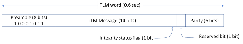
svparams.TLMPreamble = 139; % Decimal equivalent of [1 0 0 0 1 0 1 1]
svparams.TLMMessage = 0; % Contains information needed by the precise positioning service (PPS) user that is authorized user
svparams.TLMIntegrityStatusFlag = 0; % Legacy level of integrity
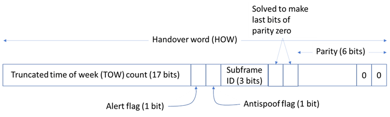
The next figure shows the fields in the HOW. The first 17 bits of the HOW indicate the 17 most significant bits (MSBs) of the time of week (TOW). The TOW is a 19-bit number, and the least significant bit (LSB) of the TOW ticks for every 1.5 seconds. The TOW in the HOW (which is the 17 MSBs of the full TOW) ticks for every 6 seconds. That is, the TOW in the HOW ticks for each subframe. For example, if the TOW value is 1000 at the current instance, then after 1.5 seconds, the TOW is 1001. After another 1.5 seconds, the TOW is 1002, and so on. If the 17 MSBs of the TOW (which is in the HOW) are considered, then for every 4 ticks of full TOW, this TOW-in-HOW ticks for one time. Because each set of 4 ticks in the full TOW corresponds to 6 seconds, the TOW-in-HOW ticks for every 6 seconds.
The 18th bit in the HOW is the alert flag that indicates that the user range accuracy (URA) of the standard positioning service (SPS) user is worse than what is indicated by the svparams.URAIndex, and user must use the current satellite at their own risk. Bit 19 in the HOW is the antispoof flag. If this flag is set, then in place of transmitting P-code, the satellite transmits the Y-code. Bits 20 to 22 in the HOW indicate the subframe ID. Last two bits of 6 bits parity are set to zero, and bits 23 and 24 are solved to set the last two bits of the parity to zero.
svparams.HOWTOW = 2000; % Decimal equivalent of 17 MSBs of TOW
svparams.HOWAlertFlag = 0; % Alert flag
svparams.AntiSpoofFlag = 0; % Antispoof flag
svparams.SubframeID = 1; % Subframe ID of starting subframe
Clock, NMCT, Ionosphere, and UTC Parameters
In theory, clocks of all satellites must be synchronized, which implies that all GPS satellite clocks must show the same time at a given moment in time. In practice, deterministic satellite clock error characteristics of bias, drift, and aging as well as satellite implementation characteristics of group delay bias and mean differential group delay exist. These errors deviate the satellite clocks from the GPS system time. These clock parameters are transmitted in subframe 1. Along with the clock information, subframe 1 also contains various configuration information. This code initializes these parameters. For a detailed description of parameters in subframe 1, see IS-GPS-200L [1].
svparams.WeekNumberMod1024 = 39; % Week number modulo 1024 to fit in 10 bits of data.
% Same as in Almanac file
svparams.CodesOnL2Channel = 2; % Value of 2 indicates C/A-code on L2 channel
% Value of 1 indicates P code on L2 channel
svparams.DataFlagForL2P = 1; % Value of 1 indicates nav data Off on P-code
% of in-phase component of L2 channel
svparams.URAIdx = 0; % User range accuracy (URA) index.
% Refer IS-GPS-200L Section 20.3.3.3.1.3 [1]
svparams.SVHealth = 0; % SV health
svparams.IODC = 0; % Issue of data, clock (IODC)
svparams.T_GD = 0; % Estimated group delay differential
svparams.t_oc = 0; % Clock data reference time
svparams.a_f2 = 0; % Second order clock correction coefficient
svparams.a_f1 = 0; % First order clock correction coefficient
svparams.a_f0 = 0; % Zeroth order clock correction coefficient
Frame 13 of subframe 4 includes the NMCT range corrections. These range corrections are done using estimated range deviation (ERD) values for each satellite. The way in which NMCT values are mapped to ERD values is defined in IS-GPS-200L [1].
svparams.NMCTAvailabilityIndicator is a 2-bit integer value that indicates the availability of NMCT data.
0 - NMCT available for both precise positioning service (PPS) user and standard positioning service (SPS) user
1 - NMCT is available only to authorized users
2 - No correction table is available to any user
3 - Reserved for future use
svparams.NMCTAvailabilityIndicator = 0; % NMCT available to both PPS and SPS users
The code initializes the ERD values for a particular satellite. The values are initialized to zero. The valid range is from -9.3 to 9.3 meters. Each array element indicates the corresponding ERD value (that is, the first element is ERD01, the second element is ERD02, and so on).
svparams.NMCTERD = zeros(30,1); % Units are in meters
A frequency dependent delay is caused due to propagation of signal through ionosphere. This delay is one of the significant errors in calculation of accurate time. To compensate for this delay due to ionosphere, dual frequency receivers need to be used for accurate positioning of the receiver. To provide a rough model of the ionosphere and delay caused by it for single frequency receivers, GPS transmits some parameters on the GPS data in subframe 4. These parameters are initialized as follows.
svparams.Ionosphere.alpha = zeros(4,1); % Units of each element in the array is seconds
svparams.Ionosphere.beta = zeros(4,1); % Units of each element in the array is seconds
Subframe 4 of the GPS LNAV data contains parameters to correlate UTC with that of the GPS time. This code initializes these parameters.
svparams.UTC.A_1 = 0; % In seconds/second
svparams.UTC.A_0 = 0; % In seconds
svparams.UTC.t_ot = 0; % In seconds
svparams.UTC.WN_t = 39; % In weeks. Same value as in almanac file
svparams.UTC.WN_LSF = 39; % In weeks. Same value as in almanac file
svparams.UTC.Delt_LS = 0; % In seconds
svparams.UTC.DN = 0; % In days
svparams.UTC.Delt_LSF = 0 % In seconds
svparams = struct with fields:
PRNIdx: 1
FrameIndices: [1x25 double]
TLMPreamble: 139
TLMMessage: 0
TLMIntegrityStatusFlag: 0
HOWTOW: 2000
HOWAlertFlag: 0
AntiSpoofFlag: 0
SubframeID: 1
WeekNumberMod1024: 39
CodesOnL2Channel: 2
DataFlagForL2P: 1
URAIdx: 0
SVHealth: 0
IODC: 0
T_GD: 0
t_oc: 0
a_f2: 0
a_f1: 0
a_f0: 0
NMCTAvailabilityIndicator: 0
NMCTERD: [30x1 double]
Ionosphere: [1x1 struct]
UTC: [1x1 struct]
Display the structure svparams.Ionosphere.
disp(svparams.Ionosphere)
alpha: [4x1 double]
beta: [4x1 double]
Display the structure svparams.UTC.
disp(svparams.UTC)
A_1: 0
A_0: 0
t_ot: 0
WN_t: 39
WN_LSF: 39
Delt_LS: 0
DN: 0
Delt_LSF: 0
Ephemeris and Almanac Data
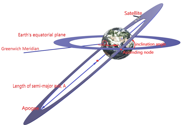
GPS satellites revolve around the Earth in an elliptical orbit, with Earth at one of the focal points of the ellipse. A set of orbital parameters that accurately defines a satellite position in this elliptical orbit is called ephemeris. Each GPS satellite transmits its own ephemeris data on subframes 2 and 3. This figure shows three orbital parameters for a satellite in the Earth-centered Earth fixed (ECEF) coordinate system. This figure does not show an actual GPS satellite, and the figure is for illustration only.
Length of semimajor axis, A: Distance from the center of the elliptical orbit of the satellite to the apogee
Inclination angle: Angle between the equatorial plane of Earth and the plane of orbit of satellite
Longitude of ascending node, Ω: Angle between the Greenwich meridian and the direction of the ascending node
Define a structure, called ephemerisparams, that stores the ephemeris parameters. The parameters that convey angle are in the units of semicircles, because the GPS standard [1] specifies these parameters in semicircles. One semicircle is equal to π radians (180 degrees).
ephemerisparams.SqrtA = 0; % Square root of length of semimajor axis
ephemerisparams.i_0 = 0; % Inclination angle (in semicircles)
ephemerisparams.Omega_0 = 0; % Longitude of ascending node at weekly epoch (in semicircles)
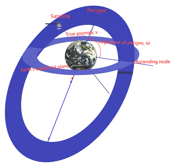
This next figure shows two orbital parameters:
Argument of perigee, ω: Angle between the direction of the ascending node and the direction of perigee
True anomaly, υ: Angle between the direction of the perigee and the direction in which current position of the satellite is present
Per Kepler's second law of planetary motion, the angular velocity (rate of change of true anomaly) is different at different locations in the orbit. You can define the mean anomaly, whose rate of change is constant over the entire orbit of the satellite. In GPS ephemeris parameters, rather than specifying true anomaly, mean anomaly is specified (from which true anomaly can be found). The algorithms that relate mean anomaly and true anomaly are given in IS-GPS-200L Table 20-IV [1].
The eccentricity of the ellipse also defines the orbit. Eccentricity gives a measure of deviation of the elliptical orbit from the circular shape.
ephemerisparams.omega = 0; % Argument of perigee (in semicircles)
ephemerisparams.M_0 = 0; % Mean anomaly at reference time (in semicircles)
ephemerisparams.e = 0; % Eccentricity of the ellipse
These ephemeris parameters aid in getting the exact location of satellite in the space.
ephemerisparams.IODE = 0; % Issue of data, ephemeris
ephemerisparams.c_rs = 0; % Amplitude of the Sine Harmonic Correction Term to
% the Orbit Radius (in meters)
ephemerisparams.Deln = 0; % Mean Motion Difference From Computed Value (in semi-circles/second)
ephemerisparams.c_uc = 0; % Amplitude of the Cosine Harmonic Correction Term to
% the Argument of Latitude (in radians)
ephemerisparams.c_us = 0; % Amplitude of the Sine Harmonic Correction Term to
% the Argument of Latitude (in radians)
ephemerisparams.t_oe = 0; % Reference time ephemeris (in seconds)
ephemerisparams.FitIntervalFlag = 0; % Fit interval flag
ephemerisparams.AODO = 0; % Age of data offset
ephemerisparams.c_ic = 0; % Amplitude of the Cosine Harmonic Correction Term to
% the Angle of Inclination (in radians)
ephemerisparams.c_is = 0; % Amplitude of the Sine Harmonic Correction Term to
% the Angle of Inclination (in radians)
ephemerisparams.c_rc = 0; % Amplitude of the Cosine Harmonic Correction Term to
% the Orbit Radius (in meters)
ephemerisparams.OmegDot = 0; % Rate of Right Ascension (in semi-circles/second)
ephemerisparams.IDOT = 0 % Rate of Inclination Angle (in semi-circles/secon)
ephemerisparams = struct with fields:
SqrtA: 0
i_0: 0
Omega_0: 0
omega: 0
M_0: 0
e: 0
IODE: 0
c_rs: 0
Deln: 0
c_uc: 0
c_us: 0
t_oe: 0
FitIntervalFlag: 0
AODO: 0
c_ic: 0
c_is: 0
c_rc: 0
OmegDot: 0
IDOT: 0
Almanac is a set of parameters that defines the position of the satellites in the orbit. In contrast with ephemeris, almanac is less precise. Additionally, ephemeris is for only one satellite, whereas almanac is for all satellites in the constellation. A receiver obtains almanac data by decoding the GPS data. A satellite continually gets this almanac data from the control segment (CS). Almanac is available to download from the navcen website. This example uses the system effective model (SEM) format of almanac data (see [2]) and extracts the almanac data as shown below.
filename = 'gpsAlmanac.txt'; % Almanac file name (this file should be in current folder)
% Use any almanac file
almanacparams = HelperGPSAlmanac2Struct(filename)
almanacparams = struct with fields:
SatellitesPRNIndices: [31x1 double]
WeekNumModulo1024: 39
t_oa: 589824
Data: [1x31 struct]
Generate GPS Signal
To generate a GPS signal at the baseband, follow these steps.
Generate the navigation data bits at 50 bits per second.
Generate the C/A-code at 1.023 mega chips per second.
Perform the XOR operation of C/A-code with the navigation data to spread the data.
BPSK-modulate the C/A-code chips by mapping bit 0 to +1 and bit 1 to -1.
Repeat above three steps for P-code at a chip rate of 10.23 mega chips per second.
Repeat each C/A-code chip 10 times to match the P-code frequency.
Place P-code and C/A-code on appropriate I and Q branches to create a complex baseband signal.
If needed, write this baseband waveform to a file for later use.
After all of the parameters for the navigation data and spreading code are initialized, generate legacy GPS navigation data using the helper function HelperGPSLNAVData.
lnavData = HelperGPSLNAVData(svparams,ephemerisparams,almanacparams); % Generates data for given FrameIndices
Because the GPS data is at 50 bits per second, and the C/A-code is at 1.023 mega chips per second, every data bit corresponds to 20460 C/A-code chips. Because creating chips for all of the data at a single time costs a great deal of memory, C/A-code spreading is done for one LNAV data bit at a time within a loop. The PRN code rate is referred to as "chip rate" rather than "bit rate" to differentiate the notation with the data bit rate. In a navigation system, the spreading code (in this example C/A-code or P-code) is called a ranging code because this code is used at the receiver to calculate the propagation time of the signal. The distance from the satellite to the receiver is measured by multiplying the propagation time with the speed of light in free space.
prnCAChipRate = 1.023e6; % In chips/second
gpsDataRate = 50; % In bits/second
Number of chips in one data bit is chip rate/data rate.
numCAChipsPerDataBit = prnCAChipRate/gpsDataRate
numCAChipsPerDataBit = 20460
The C/A-code is a fixed binary-valued vector for a given data bit, so generating the C/A-code for every data bit that is transmitted is not necessary. Generate the C/A-code corresponding to one navigation data bit outside the loop.
CACode = HelperGPSCACode(svparams.PRNIdx,numCAChipsPerDataBit);
Take one bit of navigation data and spread using the P-code. Take length of the P-code to match in time the C/A-code length that is already taken. Because the C/A-code is at the rate of 1.023 mega chips per second with 20,460 chips per one bit of navigation data, and P-code is at the rate of 10.23 mega chips per second, 204,600 chips of P-code exist for one bit of navigation data.
numPChipsPerDataBit = numCAChipsPerDataBit*10 % Because chip rate of P-code is 10 times the chip rate of C/A-code
numPChipsPerDataBit = 204600
The length of the P-code is such that it has a periodicity of 1 week. P-code chipping at the rate of 10.23 mega chips per second implies that 10.23x10^6 chips exist for every second. Because one week contains 604,800 seconds, the length of the P-code in one period is 10.23*10^6 * 604800 = 6187104000000 chips. To generate the P-code along with the length of sequence, the number of chips that are elapsed from the beginning of the week is needed, which is calculated from the HOWTOW value of the first subframe and its bit index.
numSecondsElapsed = (svparams.HOWTOW-1)*6; % Because each subframe is processed in 6 seconds
Initialize the file into which the waveform is written.
if WriteWaveformToFile == 1
bbWriter = comm.BasebandFileWriter('Waveform.bb',10.23e6,0);
end
Independently process each navigation data bit in a loop.
for iDataBit = NavDataBitStartIndex:NavDataBitEndIndex
spreadedCA = xor(CACode,lnavData(iDataBit));
M = 2; % Modulation order (for BPSK, M = 2)
bpskSigCA = pskmod(double(spreadedCA),M);
Due to these two reasons, the number of P-code chips that are processed just before the start of the data bit in consideration is calculated as shown in this code.
Every second, 10.23*10^6 P-code chips are processed.
Each data bit is spread with numPChipsPerDataBit number of P-code chips.
numPChipsPassed = round(numSecondsElapsed*10.23*10^6+(iDataBit-1)*numPChipsPerDataBit);
Generate the P-code.
PCode = HelperGPSPCode(numPChipsPerDataBit,svparams.PRNIdx,numPChipsPassed);
spreadedWithP = xor(PCode,lnavData(iDataBit));
BPSK-modulate the P-code.
bpskSigP = pskmod(double(spreadedWithP),M);
Generate the baseband waveform of the GPS L1 signal by placing the P-code on the I-branch and C/A-code on the Q-branch. Before the baseband waveform is generated, the BPSK signal that is generated by spreading with the C/A-code is repeated 10 times (because the P-code is 10 times faster than the C/A-code). Unlike a communication link, which typically has a pulse shaping filter in the digital baseband, a GPS transmitter does not have a pulse shaping filter. For precise ranging, a satellite receiver must reproduce the spreading waveform, which can be accomplished by a rectangular pulse. Spectral efficiency of the signal is not a major concern in navigation applications.
repeatedBPSKSigCA = repelem(bpskSigCA(:),10);
gpsBBWaveform = bpskSigP(:) + 1j*repeatedBPSKSigCA(:);
if WriteWaveformToFile == 1
bbWriter(gpsBBWaveform);
end
end
Close the file if it is opened.
if WriteWaveformToFile == 1
release(bbWriter);
end
Signal Visualization
Plot autocorrelation of the C/A-code and visualize the spectrum of the GPS signals.
if ShowVisualizations
The ranging codes designed for GPS have very good autocorrelation and crosscorrelation properties. Autocorrelation of the sequence is near-zero except at zero delay, and crosscorrelation of two different sequences is near-zero. As the C/A-code is periodic with period of 1023 bits, autocorrelation has a peak for a delay of every 1023 bits.
lags = (-1023:1023).';
plot(lags,xcorr(real(bpskSigCA(1:1023)),1023));
grid on;
xlabel('Number of Samples Delayed')
ylabel('Autocorrelation Value')
title('Autocorrelation of GPS C/A-Code')
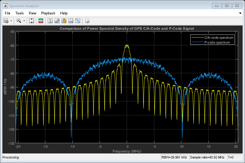
The spectrum plot shows the comparison of the power spectral density of signals spread with C/A-code and P-code. The plot shows that the P-code is wider.
repeatFactor = 40;
% Repeat the generated BPSK signal of C/A-code to see the adjacent bands spectrum
updataCA = repmat(bpskSigCA(:).',repeatFactor,1);
updataCA = real(updataCA(:));
% Repeat the generated BPSK signal of P-code to see the adjacent bands spectrum
updataP = repmat(bpskSigP(:).',repeatFactor/10,1); % Repeat the P-code ten times less as every chip of C/A-code correspond to 10 chips of P-code
updataP = real(updataP(:));
caAndPCodeScope = dsp.SpectrumAnalyzer('SampleRate',prnCAChipRate*repeatFactor, ...
'PlotAsTwoSidedSpectrum',true, ...
'SpectrumType','Power density', ...
'AveragingMethod','Exponential', ...
'SpectrumUnits','dBW', ...
'YLimits',[-130, -50], ...
'Title','Comparison of Power Spectral Density of GPS C/A-Code and P-Code Signal', ...
'ShowLegend',true, ...
'ChannelNames',{'C/A-code spectrum','P-code spectrum'});
caAndPCodeScope([updataCA,updataP]);
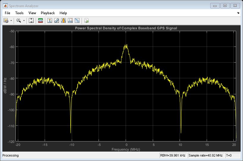
Plot the signal power spectral density at the baseband. To observe the adjacent band spectrum for the GPS signal, repeat the signal at the baseband.
repeatFactor = 4;
% Repeating the generated BPSK signal to see the adjacent bands spectrum
updata = repmat(gpsBBWaveform(:).', repeatFactor, 1);
updata = updata(:);
bbscope = dsp.SpectrumAnalyzer('SampleRate',10*prnCAChipRate*repeatFactor, ...
'PlotAsTwoSidedSpectrum',true, ...
'SpectrumType','Power density', ...
'AveragingMethod','Exponential', ...
'SpectrumUnits','dBW', ...
'YLimits',[-120,-50], ...
'Title', 'Power Spectral Density of Complex Baseband GPS Signal');
bbscope(updata);
end

Further Exploration
This example uses three structures: svparams, ephemerisparams, and almanacparams. These structures generate GPS data bits and the navigation signal in the baseband. You can also replace the parameters in each of these structures and observe how the GPS data is generated. You can change the ephemeris parameters with an existing real data set and pass those parameters into the ephemeris. Additionally, you can specify your own almanac file. If using your own almanac file, the week number in the almanac file and the week number in the svparams structure must match.
Further, this example shows how to generate a GPS baseband waveform, which can be extended to generate an intermediate frequency (IF) waveform from the baseband waveform by multiplying a cosine signal on the I-branch and a sine signal on the Q-branch.
Additionally, this example shows how to generate a GPS waveform from one satellite, which can be combined along with multiple satellite PRN codes to get an integrated signal.
Appendix
This example uses these data and helper files:
gpsAlmanac.txt - Almanac data file downloaded from Navcen website
HelperGPSAlmanac2Struct.m - Convert text file of almanac to structure
HelperGPSCACode.m - Generate C/A-code to spread data
HelperGPSPCode.m - Generate P-code to spread data
HelperGPSLNAVData.m - Create legacy navigation frame from data that is in structures
Bibliography
[1] IS-GPS-200, Rev: L; NAVSTAR GPS Space Segment/Navigation User Segment Interfaces; May 14, 2020; Code Ident: 66RP1.
[2] ICD-GPS-240, Rev: C; Navstar GPS Control Segment to User Support Community Interfaces; March 4, 2019; Code Ident: 66RP1.


 99
99


 被折叠的 条评论
为什么被折叠?
被折叠的 条评论
为什么被折叠?
 到【灌水乐园】发言


