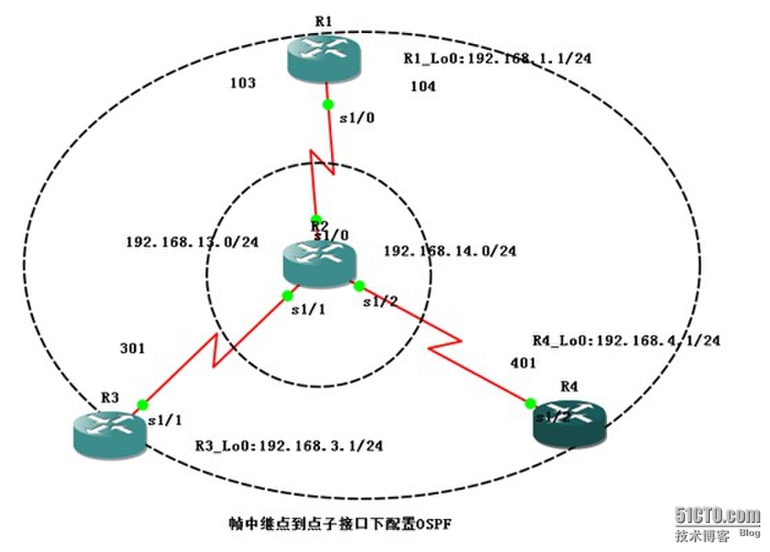
帧中继点到点子接口下配置OSPF
1、实验目的
通过本实验可以掌握
1)帧中继点到点子接口的特征;
2)帧中继点到点子接口的配置;
3)帧中继点到点子接口模式下OSPF的配置和调试
2、实验拓扑图
3、实验步骤
本实验在路由器R1上创建2个点到点子接口,分别与路由器R3和R4上创建的点到点子接口形成点到点连接,拓扑结构采用Hub-and-Spoke结构,整个网络运行OSPF路由协议。
1)配置路由器R1:
R1#conf t
Enterconfiguration commands, one per line. End with CNTL/Z.
R1(config)#intloopback 0
R1(config-if)#ipaddress 192.168.1.1 255.255.255.0
R1(config-if)#noshutdown
R1(config-if)#ipospf network point-to-point
R1(config-if)#exit
R1(config)#ints1/0
R1(config-if)#noip address
R1(config-if)#encapsulationframe-relay
R1(config-if)#noframe-relay inverse-arp
R1(config-if)#noshutdown
R1(config-if)#exit
R1(config)#int s1/0.13 point-to-point //创建帧中继点到点子接口
R1(config-subif)#ipaddress 192.168.13.1 255.255.255.0
R1(config-subif)#frame-relay interface-dlci 103 //配置帧中继映射
【提示】
点到点子接口下不能使用“frame-relay map ip”命令来配置帧中继的映射,而是改用“frame-relay interface-dlci”命令来配置
R1(config-fr-dlci)#exit
R1(config-subif)#exit
R1(config)#ints1/0.14 point-to-point
R1(config-subif)#ipaddress 192.168.14.1 255.255.255.0
R1(config-subif)#frame-relayinterface-dlci 104
R1(config-fr-dlci)#exit
R1(config-subif)#exit
R1(config)#routerospf 1
R1(config-router)#router-id1.1.1.1
R1(config-router)#network192.168.1.0 0.0.0.255 area 0
R1(config-router)#network192.168.13.0 0.0.0.255 area 0
R1(config-router)#network192.168.14.0 0.0.0.255 area 0
2)配置路由器R3
R3#conf t
Enterconfiguration commands, one per line. End with CNTL/Z.
R3(config)#intloopback 0
R3(config-if)#ipaddress 192.168.3.1 255.255.255.0
R3(config-if)#noshow
R3(config-if)#ipos
R3(config-if)#ipospf net
R3(config-if)#ipospf network p
R3(config-if)#ipospf network point-to-p
R3(config-if)#ipospf network point-to-point
R3(config-if)#exit
R3(config)#ints1/1
R3(config-if)#noip address
R3(config-if)#encapsulationframe-relay
R3(config-if)#noframe-relay inverse-arp
R3(config-if)#noshutdown
R3(config-if)#exit
R3(config)#ints1/1.13 point-to-point
R3(config-subif)#ipaddress 192.168.13.3 255.255.255.0
R3(config-subif)#frame-relayinterface-dlci 301
R3(config-fr-dlci)#exit
R3(config-subif)#exit
R3(config)#routerospf 1
R3(config-router)#router-id3.3.3.3
R3(config-router)#network192.168.13.0 0.0.0.255 area 0
R3(config-router)#network192.168.3.0 0.0.0.255 area 0
3)配置路由器R4
R4#conf t
Enterconfiguration commands, one per line. End with CNTL/Z.
R4(config)#intloopback 0
R4(config-if)#ipaddress 192.168.4.1 255.255.255.0
R4(config-if)#ipospf network point-to-point
R4(config-if)#noshutdown
R4(config-if)#exit
R4(config)#ints1/2
R4(config-if)#noip address
R4(config-if)#encapsulationframe-relay
R4(config-if)#noframe-relay inverse-arp
R4(config-if)#noshutdown
R4(config-if)#exit
R4(config)#ints1/2.14 point-to-point
R4(config-subif)#ipaddress 192.168.14.4 255.255.255.0
R4(config-subif)#frame-relayinterface-dlci 401
R4(config-fr-dlci)#exit
R4(config-subif)#exit
R4(config)#routerospf 1
R4(config-router)#router-id4.4.4.4
R4(config-router)#network192.168.4.0 0.0.0.255 area 0
R4(config-router)#network192.168.14.0 0.0.0.255 area 0
4)配置帧中继
R2#conf t
Enterconfiguration commands, one per line. End with CNTL/Z.
R2(config)#frame-relayswitching
R2(config)#ints1/0
R2(config-if)#clockrate 64000
R2(config-if)#encapsulationframe-relay
R2(config-if)#frame-relaylmi-type cisco
R2(config-if)#frame-relayintf-type dce
R2(config-if)#frame-relayroute 103 interface s1/1 301
R2(config-if)#frame-relayroute 104 interface s1/2 401
R2(config-if)#noshutdown
R2(config-if)#exit
R2(config)#ints1/1
R2(config-if)#clockrate 64000
R2(config-if)#encapsulationframe-relay
R2(config-if)#frame-relaylmi-type cisco
R2(config-if)#frame-relayintf-type dce
R2(config-if)#frame-relayroute 301 interface s1/0 103
R2(config-if)#noshutdown
R2(config-if)#exit
R2(config)#ints1/2
R2(config-if)#clockrate 64000
R2(config-if)#encapsulationframe-relay
R2(config-if)#frame-relaylmi-type cisco
R2(config-if)#frame-relayintf-type dce
R2(config-if)#frame-relayroute 401 interface s1/0 104
R2(config-if)#noshutdown
4、实验调试
1)show frame-relay map
R1#showframe-relay map
Serial1/0.13(up): point-to-point dlci, dlci 103(0x67,0x1870), broadcast
status defined, active
Serial1/0.14(up): point-to-point dlci, dlci 104(0x68,0x1880), broadcast
status defined, active
R1#
R3#showframe-relay ma
R3#showframe-relay map
Serial1/1.13(up): point-to-point dlci, dlci 301(0x12D,0x48D0), broadcast
status defined, active
R3#
R4#shframe-relay map
Serial1/2.14(up): point-to-point dlci, dlci 401(0x191,0x6410), broadcast
status defined, active
R4#
以上输出表明路由器使用了点到点子接口,由于点到点的特性,在每条映射条目中,只看到该子接口下的DLCI,没有对端的IP地址,这一点和多点子接口是不同的。
2)show ip ospf interface
R1#showip ospf interface
Serial1/0.14is up, line protocol is up
Internet Address 192.168.14.1/24, Area 0
Process ID 1, Router ID 1.1.1.1, Network TypePOINT_TO_POINT, Cost: 64
//OSPF网络类型为点到点,在帧中继点到点子接口网络上,OSPF接口默认的网络类型为POINT_TO_POINT。
Transmit Delay is 1 sec, StatePOINT_TO_POINT,
Timer intervals configured, Hello 10, Dead40, Wait 40, Retransmit 5
// POINT_TO_POINT模式下,Hello周期为10s
oob-resync timeout 40
Hello duein 00:00:06
……(此处省略部分输出)
3)show ip route
R1#showip route ospf
O 192.168.4.0/24 [110/65] via 192.168.14.4,00:18:11, Serial1/0.14
O 192.168.3.0/24 [110/65] via 192.168.13.3,00:18:11, Serial1/0.13
R1#
R3#sh iproute ospf
O 192.168.14.0/24 [110/128] via 192.168.13.1,00:18:50, Serial1/1.13
O 192.168.4.0/24 [110/129] via 192.168.13.1,00:18:50, Serial1/1.13
O 192.168.1.0/24 [110/65] via 192.168.13.1,00:18:50, Serial1/1.13
R3#
R4#sh iproute ospf
O 192.168.13.0/24 [110/128] via 192.168.14.1,00:19:41, Serial1/2.14
O 192.168.1.0/24 [110/65] via 192.168.14.1,00:19:41, Serial1/2.14
O 192.168.3.0/24 [110/129] via 192.168.14.1,00:19:41, Serial1/2.14
R4#
以上个路由器的路由表的输出表明了整个网络的互通的。
4)show ip ospfneighbor detail
R3#showip ospf neighbor detail
Neighbor 1.1.1.1, interface address192.168.13.1
In the area 0 via interface Serial1/1.13
Neighbor priority is 0, State is FULL, 6state changes
DR is 0.0.0.0 BDR is 0.0.0.0
//点到点模式的DR和BDR是“0.0.0.0”
Options is 0x52
LLS Options is 0x1 (LR)
Dead timer due in 00:00:37
Neighbor is up for 00:37:02
Index 1/1, retransmission queue length 0,number of retransmission 0
First 0x0(0)/0x0(0) Next 0x0(0)/0x0(0)
Last retransmission scan length is 0,maximum is 0
Last retransmission scan time is 0 msec,maximum is 0 msec
R3#
以上输出表明路由器R3通过自接口S1/1.13与路由器R1建立邻接关系。
转载于:https://blog.51cto.com/19880423/1324756


 111
111


 被折叠的 条评论
为什么被折叠?


