


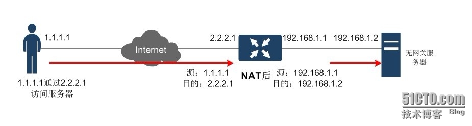
最近在QQ群中聊天的时候有一位群友提出了一个问题,内网服务器在没有网关的情况下怎么样发布到公网中去,同时网络的出口也只有一个公网地址,提出问题网络的拓扑如下:
图:网友给的拓扑图
拓扑思路即要求描述:
1. 内网服务器的IP地址为192.168.1.2,由于某种要求而不能设置网关
2. 出口设备的内网地址为192.168.1.1,同时这个地址也为内网其他PC的网关地址
3. 出口设备仅仅有一个公网地址为2.2.2.1
4. 将内网服务器192.168.1.2:23映射为2.2.2.1:23,公网用户1.1.1.1通过 telnet 2.2.2.1可以连接到内网服务器的telnet端口
看到这个问题及给出的拓扑思路后,用GNS3搭建了一个网络拓扑图如下:

图:GNS3搭建的网络拓扑
GNS3网络拓扑介绍:
1. 路由器R1的公网接口fa0/0地址为:2.2.2.1,内网IP地址为192.168.1.1;
2. 路由器R2模拟内网服务器,接口IP为192.168.1.2,同时no ip routing关闭路由功能即不设置网关,开启telnet功能,密码为cisco
3. 路由器R5模拟为内部普通PC,地址为192.168.1.11,可正常访问互联网;
4. 路由器R4模拟为公网普通用户,地址为1.1.1.1
本文的主要内容为路由器R1的配置,配置思路如下:
1. 配置NAT使内网用户能正常访问Internet
2. 配置Static NAT将192.168.1.2:23映射为2.2.2.1:23
3. 配置NAT 使Internet用户在访问内部服务器192.168.1.2时将源IP地址转换为192.168.1.1
注:本例若使用常规的NAT转换设置,即在接口上设置ip nat inside source 或ip nat outside source 命令,然后将在全局配置下使用ip nat inside source 命令将不能完全满足这位网友的要求(主要是不能将公网地址IP为192.168.1.1来访问内部服务器,如果稍做变通同将公网IP转换为其他内网IP如192.168.1.3则可),为了技术爱好,也为了完全满足这位网友的要求,本文将给出另一种解决方法。
方法一:
在内外网接口上启用ip nat enable命令 ,在全局配置模式下使用ip nat source 命令来满足需求配置如下:
路由器R1的配置如下:
!
!
version 12.4
service timestamps debug datetime msec
service timestamps log datetime msec
no service password-encryption
!
hostname R1
!
boot-start-marker
boot-end-marker
!
!
no aaa new-model
!
resource policy
!
memory-size iomem 5
ip subnet-zero
!
!
ip cef
no ip domain lookup
ip domain name lab.local
!
!
interface FastEthernet0/0
ip address 2.2.2.1 255.255.255.0
ip nat enable //在接口上启用nat,注意ip nat enable 与ip nat outside的区别
ip virtual-reassembly
duplex auto
speed auto
!
interface FastEthernet1/0
ip address 192.168.1.1 255.255.255.0
ip nat enable //在接口上启用nat,注意ip nat enable 与ip nat inside的区别
ip virtual-reassembly
duplex auto
speed auto
!
no ip http server
no ip http secure-server
!
ip classless
ip route 0.0.0.0 0.0.0.0 2.2.2.3
!
ip nat source list 110 interface FastEthernet0/0 overload //内网到外网的NAT转换
ip nat source list 120 interface FastEthernet1/0 overload //外网到内网的NAt转换
ip nat source static tcp 192.168.1.2 23 2.2.2.1 23 extendable //服务器23端口映射
!
access-list 110 permit ip 192.168.1.0 0.0.0.255 any
access-list 120 permit tcp any host 2.2.2.1 eq telnet
no cdp run
!
!
control-plane
!
!
line con 0
exec-timeout 0 0
privilege level 15
logging synchronous
line aux 0
exec-timeout 0 0
privilege level 15
logging synchronous
line vty 0 4
login
!
!
end
路由器R2模拟内网服务器的配置如下:
!
version 12.4
service timestamps debug datetime msec
service timestamps log datetime msec
no service password-encryption
!
hostname R2
!
boot-start-marker
boot-end-marker
!
enable secret 5 $1$/FLK$scltNBoUUNSyP4tMP8vaD1
!
no aaa new-model
!
resource policy
!
memory-size iomem 5
ip subnet-zero
no ip routing //取消设备的路由功能,并且不设置网关
!
!
no ip cef
no ip domain lookup
ip domain name lab.local
!
!
interface FastEthernet0/0
no ip address
no ip route-cache
shutdown
duplex auto
speed auto
!
interface FastEthernet1/0
ip address 192.168.1.2 255.255.255.0
no ip route-cache
duplex auto
speed auto
!
no ip http server
no ip http secure-server
!
ip classless
!
control-plane
!
line con 0
exec-timeout 0 0
privilege level 15
logging synchronous
line aux 0
exec-timeout 0 0
privilege level 15
logging synchronous
line vty 0 4 //开启telnet
password cisco
login
!
!
end
测试:
在公网用户1.1.1.1上 telnet 2.2.2.1 通过,如下图:

在内网PC上ping 公网地址1.1.1.1通过,如下图:

以上测试全部正常,完成要求
示例中使用ip nat source来开启NAT与我们常规使用ip nat inside source 的方法来启用NAT不仅仅在命令格式上不同,并且在数据包的转换过程中也有很大不同。
ip nat inside source 数据包由inside 接口outside接口发包时,是先路由再NAT转换;而数据包由outside 接口向inside接口发包时是先NAT转换再路由,数据包的发送方向不同,则处理过程也不同
而使用ip nat source做NAT转换时,在需要NAT转换接口上使用的命令为ip nat enable,数据包在由一个接口向另一个接口发包时,顺序是先路由再NAT然后再路由(第一个路由只是匹配一下路由,而没有真正的路由行为,第二个路由则是真实的路由行为),不管数据包从哪个接口发向哪个接口,处理过程都是一样的。
正是由于两种NAT转换方法对数据包的处理方式不同,才造成了使用ip nat inside source不能完全符合第一副图中的要求,而使用ip nat source则可以完全符合图中的要求,如果将图中的要求稍微改变一下用ip nat inside source 也是可以的,这个将在下一篇文章中介绍。
转载于:https://blog.51cto.com/wyywei/1262354


 3185
3185

 被折叠的 条评论
为什么被折叠?
被折叠的 条评论
为什么被折叠?
 到【灌水乐园】发言


