


fanbeam
Description
F = fanbeam(I,D)
computes the fan-beam projection data (sinogram)
F from the image I.
Each column of F contains fan-beam projection
data at one rotation angle. D is the distance
from the fan-beam vertex to the center of rotation.
F = fanbeam(I,D,Name,Value)
uses name-value pairs to specify the rotation increment and sensor
spacing.
fan_sensor_positions and the rotation
angles where the fan-beam projections are calculated in
fan_rotation_angles.
Examples
Compute Fan-beam Projections for Rotation Angles Over Entire Image
Set the IPT preference to make the axes visible.
iptsetpref('ImshowAxesVisible','on')
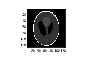
Create a sample image and display it.
ph = phantom(128);
imshow(ph)
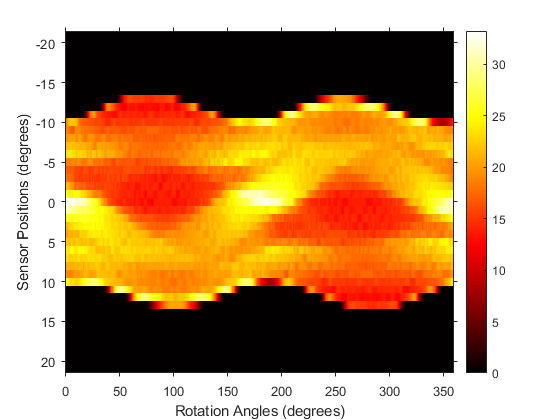
Calculate the fanbeam projections and display them.
[F,Fpos,Fangles] = fanbeam(ph,250);
figure
imshow(F,[],'XData',Fangles,'YData',Fpos,...
'InitialMagnification','fit')
axis normal
xlabel('Rotation Angles (degrees)')
ylabel('Sensor Positions (degrees)')
colormap(gca,hot), colorbar
Compute Radon and Fan-beam Projections and Compare Results
Compute fan-beam projections for 'arc' geometry.
I = ones(100);
D = 200;
dtheta = 45;
[Farc,FposArcDeg,Fangles] = fanbeam(I,D,...
'FanSensorGeometry','arc',...
'FanRotationIncrement',dtheta);
Convert angular positions to linear distance along x-prime axis.
FposArc = D*tan(FposArcDeg*pi/180);
Compute fan-beam projections for 'line' geometry.
[Fline,FposLine] = fanbeam(I,D,...
'FanSensorGeometry','line',...
'FanRotationIncrement',dtheta);
Compute the corresponding Radon transform.
[R,Rpos]=radon(I,Fangles);
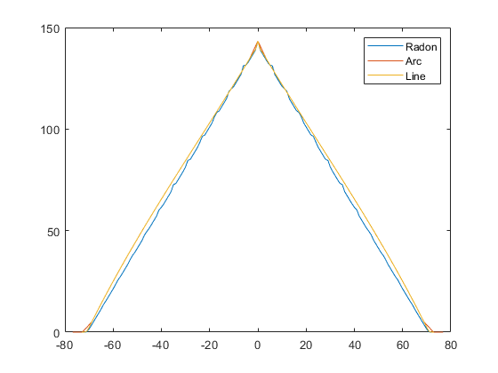
Display the three projections at one particular rotation angle. Note the three are very similar. Differences are due to the geometry of the sampling, and the numerical approximations used in the calculations.
figure
idx = find(Fangles==45);
plot(Rpos,R(:,idx),...
FposArc,Farc(:,idx),...
FposLine,Fline(:,idx))
legend('Radon','Arc','Line')
Input Arguments
I — Input image
2-D numeric matrix | 2-D logical matrix
Input image, specified as a 2-D numeric or logical
matrix.
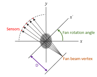
D — Distance from fan beam vertex to center of rotation
positive number
Distance in pixels from the fan beam vertex to the
center of rotation, specified as a positive number.
The center of rotation is the center pixel of the
image, defined as
floor((size(I)+1)/2).
D must be large enough to
ensure that the fan-beam vertex is outside of the
image at all rotation angles. See Tips for guidelines on specifying
D. The figure illustrates
D in relation to the fan-beam
vertex for one fan-beam geometry.
Name-Value Pair Arguments
Specify optional
comma-separated pairs of Name,Value arguments. Name is
the argument name and Value is the corresponding value.
Name must appear inside quotes. You can specify several name and value
pair arguments in any order as
Name1,Value1,...,NameN,ValueN.Example:F =
fanbeam(I,D,'FanRotationIncrement',5)
'FanRotationIncrement' — Fan-beam rotation angle increment
1 (default) | positive scalar
Fan-beam rotation angle increment in degrees, specified as the comma-separated pair
consisting of 'FanRotationIncrement' and a positive scalar.

Data Types:double
'FanSensorGeometry' — Fan-beam sensor positioning
'arc' (default) | 'line'
Fan-beam sensor positioning, specified as the comma-separated pair consisting of
'FanSensorGeometry' and one of the following
values.
ValueMeaningDiagram'arc'Sensors are spaced at equal angles along a circular arc at
distance D from the center of
rotation.
FanSensorSpacing
defines the angular spacing in degrees.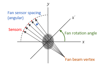
'line'Sensors are spaced at equal distances along a line that is
parallel to the x' axis. The closest sensor
is distance D from the center of
rotation.
FanSensorSpacing
defines the distance between fan-beams on the
x' axis, in pixels.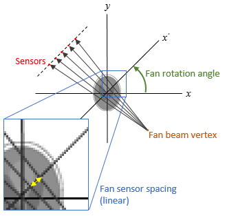
'FanSensorSpacing' — Fan-bean sensor spacing
1 (default) | positive scalar
Fan-bean sensor spacing, specified as the comma-separated pair consisting of
'FanSensorSpacing' and a positive scalar.
If FanSensorGeometry is 'arc',
then FanSensorSpacing defines the angular spacing in
degrees.
If FanSensorGeometry is 'line',
then FanSensorSpacing defines the linear distance
between fan-beams, in pixels. Linear spacing is measured on the
x' axis.
Data Types:double
Output Arguments
F — Fan-beam projection data
numsensors-by-numangles
numeric matrix
Fan-beam projection data, returned as a
numsensors-by-numangles
numeric matrix. numsensors is the
number of fan-beam sensors and
numangles is the number of
fan-beam rotation angles. Each column of
F contains the fan-beam sensor
samples at one rotation angle.
Data Types:double
fan_sensor_positions — Location of fan-beam sensors
numsensors-by-1 numeric
vector
Location of fan-beam sensors, returned as a
numsensors-by-1 numeric
vector.
If FanSensorGeometry is
'arc' (the default), then
fan_sensor_positions contains
the fan-beam spread angles.
If FanSensorGeometry is
'line', then
fan_sensor_positions contains
the fan-beam sensor positions along the
x' axis. See
FanSensorSpacing for more
information.
fanbeam determines the number of
sensors by calculating how many beams are required
to cover the entire image for any rotation angle.
Fewer sensors are required to cover the image when
the distance D between the
fan-beam vertex and the center of rotation is
large.
Data Types:double
fan_rotation_angles — Rotation angle of fan-beam sensors
1-by-numangles numeric
vector
Rotation angle of fan-beam sensors, returned as a
1-by-numangles numeric vector.
numangles is
Data Types:double
Tips
As a guideline, try making D a few pixels larger than
half the image diagonal dimension, calculated as follows.
sqrt(size(I,1)^2 + size(I,2)^2)
The values returned in F are a numerical approximation of
the fan-beam projections. The algorithm depends on the Radon transform,
interpolated to the fan-beam geometry. The results vary depending on the
parameters used. You can expect more accurate results when the image is
larger, D is larger, and for points closer to the middle
of the image, away from the edges.
References
[1] Kak, A.C., & Slaney, M., Principles
of Computerized Tomographic Imaging, IEEE Press, NY,
1988, pp. 92-93.
Introduced before R2006a


 4202
4202


 被折叠的 条评论
为什么被折叠?
被折叠的 条评论
为什么被折叠?
 到【灌水乐园】发言


