


前言
本文主要介绍Orange PiPC2 的启动镜像制作,包含一下内容,sunxi H5芯片的bootrom,以及spiflash的镜像制作,tf卡的镜像制作等内容。
镜像制作的话和bootrom内容涉及紧密联系,如果不了解可以先看这篇文章OrangePIPC2—bootrom
sunxi(sunxi represents the family of ARM SoCs from Allwinner Technology)
引用https://linux-sunxi.org/BROM
本文针对sunxi的H5做下norflash和tf卡的镜像制作方法。
因为在bootrom中有对nor和tf卡的处理,所以如下在附上启动的特殊说明。eGON就是在bootrom中的一段代码。
大致的启动说明
在文件中uboot----\board\sunxi\README.sunxi64
Boot process
============
The on-die BROM code will try several methods to load and execute the firmware.
On a typical board like the Pine64 this will result in the following boot order:

1) Reading 32KB from sector 16 (@8K) of the microSD card to SRAM A1. If the
BROM finds the magic "eGON" header in the first bytes, it will execute that
code. If not (no SD card at all or invalid magic), it will:
2) Try to read 32KB from sector 16 (@8K) of memory connected to the MMC2
controller, typically an on-board eMMC chip. If there is no eMMC or it does
not contain a valid boot header, it will:
3) Initialize the SPI0 controller and try to access a NOR flash connected to
it (using the CS0 pin). If a flash chip is found, the BROM will load the
first 32KB (from offset 0) into SRAM A1. Now it checks for the magic eGON
header and checksum and will execute the code upon finding it. If not, it will:
4) Initialize the USB OTG controller and will wait for a host to connect to
it, speaking the Allwinner proprietary (but deciphered) "FEL" USB protocol.


To boot the Pine64 board, you can use U-Boot and any of the described methods.
- 针对tf卡从16个扇区(512B)也就是8K的地方读32K带sdram中
- nor从0地址读32k到sdram中
uboot的debug打印默认不输出,只要在当前c文件最前头#define _DEBUG 1 debug()就会打印出来了
spl的bin文件在编译后再uboot\spl目录下sunxi-spl.bin
bootrom处理
bootrom是固话在cpu中的一段逻辑代码,sunxi以及开源了,可以去看,
大致流程是上电会挨个扫描介质,确定了什么介质就自动从介质中拷贝spl到sram中运行,比如spinorflash重0地址开始拷贝,sd卡重8k位置开始拷贝,都是bootrom写死了,bootrom是根据硬件知道是去哪个介质拷贝spl,但spl咋知道重哪里拷贝uboot到ddr运行呢,这里bootrom就搞了下小动作,在spl头中修改了某些信息,然后spl就是根据这些信息知道当前spl是从哪里启动的,然后就去相对应的介质中拷贝uboot,
spl 头信息在boot_media,
在uboot代码中有定义 arch/arm/include/asm/arch-sunxi/spl.h
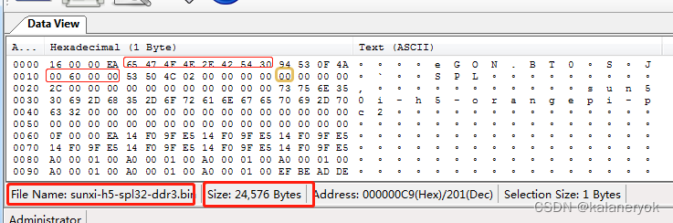
struct boot_file_head ,可以打开uboot spl/sunxi-spl.bin 查看头
H3 可以直接用uboot编译出来的spl文件,H5不知道为啥不行,我是用别人编译出来的给用的。
uboot spl的检测处理过程
注意board_init_r这个是common/spl/spl.c 的逻辑,不同平台可能有自己的实现spl–board_init_r
sunxi用的是通用spl逻辑,common/board_r.c的board_init_r是uboot的初始化逻辑,记得区分
board_init_r-》board_boot_order-》spl_boot_device-》sunxi_get_boot_device 读spl头判断哪里启动的
sunxi_get_boot_source, 这个就是spl的代码中检测告知spl我是从哪里启动的
struct boot_file_head *egon_head = (void )SPL_ADDR; 这个地址就是sram地址,由bootrom加载到这个地址的同时bootrom会修改这个头信息用来传递启动介质信息 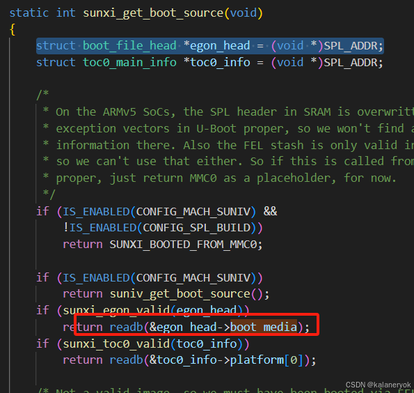
spl头信息结构体就是splbin文件,boot_media这个字段就会在bootrom中被修改,这个就是bootrom的一点小操作,传递了启动介质信息
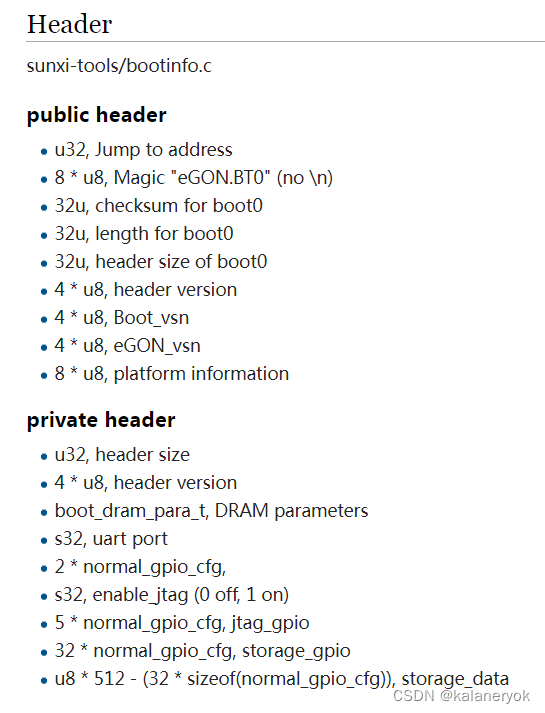
struct boot_file_head {
uint32_t b_instruction; / one intruction jumping to real code /
uint8_t magic[8]; / =“eGON.BT0” or “eGON.BT1”, not C-style str /
uint32_t check_sum; / generated by PC /
uint32_t length; / generated by PC /
uint32_t dt_name_offset; / since v0.2, set by mksunxiboot /
uint32_t dram_size; / in MiB, since v0.3, set by SPL /
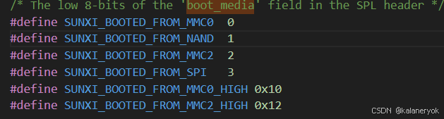
uint32_t boot_media; / written here by the boot ROM */
boot_media 就会被赋值城0 就表示mmc ,1表示nand等
nor启动
eGON 中对nor的处理
在bootrom的汇编文件里可以看到对nor的处理是这个函数
bootrom处理的代码
load_from_spinor
对于 SPI NOR 闪存引导,BROM 为 SPI0 设置 6 MHz时钟频率,然后发出一系列读取数据字节 (03h) 命令。第一条命令从地址 0 读取 256 字节。如果识别出有效的 eGON 标头,接下来会读2次,第一次从0 地址读2048字节,第二次,从2048地址一直读完整个boot0镜像。
那么他怎么知道我的boot0多大呢,这就得益于,boot0的头了,也就是第一次读到的信息里面获得。然后跳转到boot0去运行。
几乎能对上,但是这个plt信息有点对不上,不知道为啥。
分析
前面分析镜像的读取地址由spl决定,他在spi介质中这个文件实现,spl_spi.c(common/spl)
在函数spl_spi_load_image中去哪里读镜像是payload_offs变量决定。
根据代码分析
1.默认值为CONFIG_SYS_SPI_U_BOOT_OFFS 0x8000
2. 假如OF_CONTROL使能且OF_PLATDATA不使能,那么去设备树中读取这个值,他的名字叫u-boot,spl-payload-offset,如果没有需要自己设置下,H5 这块编译没进
在这里他用的是默认值,为0x8000,大致过程从CONFIG_SYS_SPI_U_BOOT_OFFS 开始读0x40,用于检测mkimage header 64字节,以及判断是否含有fdt,
依赖
首先上面的spl_spi.c支持需要修改配置,因为spl的makefile,
obj-KaTeX parse error: Expected group after '_' at position 8: (CONFIG_̲(SPL_TPL_)MMC_SUPPORT) += spl_mmc.o
obj-KaTeX parse error: Expected group after '_' at position 8: (CONFIG_̲(SPL_TPL_)SPI_LOAD) += spl_spi.o
CONFIG_$(SPL_TPL_)SPI_LOAD 这个需要支持下(实际上不是这个文件)
这里有个插曲,我一开始一直以为是这个spl_spi.c文件配置,看了下makefile的配置也没有这个CONFIG,就感觉很起怪,搜索了下spl_spi才发现sunxi不用这个他自己有实现。
./arch/arm/mach-sunxi/spl_spi_sunxi.c:275:static int spl_spi_load_image(struct spl_image_info *spl_image,
./arch/arm/mach-sunxi/spl_spi_sunxi.c:312:SPL_LOAD_IMAGE_METHOD("sunxi SPI", 0, BOOT_DEVICE_SPI, spl_spi_load_image);

makefile:
obj-$(CONFIG_SPL_SPI_SUNXI)	+= spl_spi_sunxi.o
方法:
- 看下这个CONFIG_SPL_SPI_SUNXI是否打开
这里有个小疑问
为啥spiflash的就是运行的是spl_spi_sunxi.c而不是spl_nor.c,这里有说明说是
/*
* Loading of the payload to SDRAM is done with skipping of
* the mkimage header in this SPL NOR driver
*/
他不会有mkinage的header,而且看load代码
先解析CONFIG_SYS_OS_BASE这个地方的header如果check成功而且是linux那么就直接运行linux,如果失败再解析CONFIG_SYS_UBOOT_BASE这个地方的header,进入uboot
走向
spl_spi_load_image
	if (IS_ENABLED(CONFIG_SPL_LOAD_FIT) &&
			image_get_magic(header) == FDT_MAGIC) {  //根据u-boot.its中的images布局进行加载到相对应位置,不是uboot下的设备树,是另一个设备树文件
			struct spl_load_info load;

			debug("Found FIT\n");
			load.dev = flash;
			load.priv = NULL;
			load.filename = NULL;
			load.bl_len = 1;
			load.read = spl_spi_fit_read;
			err = spl_load_simple_fit(spl_image, &load,
						  payload_offs,
						  header);
		}
- header读到的其实是boot.its的头,这个文件是个设备树格式的文件,所以他也有头,包含了这个设备树文件的大小
- spl_load_simple_fit函数中根据实际大小再次读完整的boot.its到内存中
- 根据解析将image搬到boot.its指定的ddr中
u-boot.its
/ {
	description = "Configuration to load ATF before U-Boot";
	#address-cells = <1>;

	images {
		uboot {
			description = "U-Boot (64-bit)";
			data = /incbin/("u-boot-nodtb.bin");
			type = "standalone";
			arch = "arm64";
			compression = "none";
			load = <0x4a000000>;
		};
		atf {
			description = "ARM Trusted Firmware";
			data = /incbin/("bl31.bin");
			type = "firmware";
			arch = "arm64";
			compression = "none";
			load = <0x44000>;
			entry = <0x44000>;
		};
		fdt_1 {
			description = "sun50i-h5-orangepi-pc2";
			data = /incbin/("arch/arm/dts/sun50i-h5-orangepi-pc2.dtb");
			type = "flat_dt";
			compression = "none";
		};
	};
	configurations {
		default = "config_1";

		config_1 {
			description = "sun50i-h5-orangepi-pc2";
			firmware = "uboot";
			loadables = "atf";
			fdt = "fdt_1";
		};
	};
};
制作镜像
所以按照上面的bootrom的做法,那么久必须将boot0 也就是spl.bin烧写道flash 的0地址。那么,其他文件怎么办呢,boot1烧写的地址应该是由boot0来确定的,因为bootrom将boot0搬到sdram中后就由boot0来接管执行了。所以boot1的走向是boot0来确定的。
tftp sunxi-spl.bin
sf erase 0 0x8000
sf write 0x42000000 0 0x8000
tftp u-boot.itb
sf erase 0x8000 0x80000
sf write 0x42000000 0x8000 0x80000
- norflash的0地址烧写sunxi-spl.bin
- 把u-boot.itb烧写到0x8000位置
启动打印
resetting ...
INFO:    PSCI Affinity Map:
INFO:      AffInst: Level 0, MPID 0x0, State ON
INFO:      AffInst: Level 0, MPID 0x1, State OFF
INFO:      AffInst: Level 0, MPID 0x2, State OFF
INFO:      AffInst: Level 0, MPID 0x3, State OFF

U-Boot SPL 2018.03 (Jun 26 2022 - 20:31:13 +0800)
DRAM: 1024 MiB
>>spl:board_init_r()
Trying akk to boot from sunxi SPI
os :17
Jumping to U-Boot
SPL malloc() used lx bytes (0 KB)
loaded - jumping to U-Boot...
image entry point: 0x
NOTICE:  BL3-1: Running on H5 (1718) in SRAM A2 (@0x44000)
NOTICE:  Configuring SPC Controller
NOTICE:  BL3-1: v1.0(debug):ae787242
NOTICE:  BL3-1: Built : 20:43:27, Feb 21 2018
NOTICE:  DT: sun50i-h5-orangepi-pc2
NOTICE:  SCPI: dummy stub handler, implementation level: 000000
INFO:    BL3-1: Initializing runtime services
INFO:    BL3-1: Preparing for EL3 exit to normal world
INFO:    BL3-1: Next image address: 0x4a000000, SPSR: 0x3c9


U-Boot 2018.03 (Jun 26 2022 - 20:34:26 +0800) Allwinner Technology

CPU:   Allwinner H5 (SUN50I)
Model: OrangePi PC 2
DRAM:  1 GiB
MMC:   SUNXI SD/MMC: 0
Loading Environment from FAT... MMC: no card present
** Bad device mmc 0 **
Failed (-5)
Loading Environment from MMC... MMC: no card present
*** Warning - MMC init failed, using default environment

Failed (-5)
In:    serial
Out:   serial
Err:   serial
Net:   phy interface7
eth0: ethernet@1c30000
starting USB...
USB0:   PA: set_value: error: gpio PA0 not reserved
USB EHCI 1.00
USB1:   USB OHCI 1.0
scanning bus 0 for devices... 1 USB Device(s) found
       scanning usb for storage devices... 0 Storage Device(s) found
Hit any key to stop autoboot:  0
AK #
AK #
tf卡启动
对你写文章有帮助的贴纸http://t.zoukankan.com/emlslxl-p-5620007.html
这边文章也挺好https://zhuanlan.zhihu.com/p/391101179
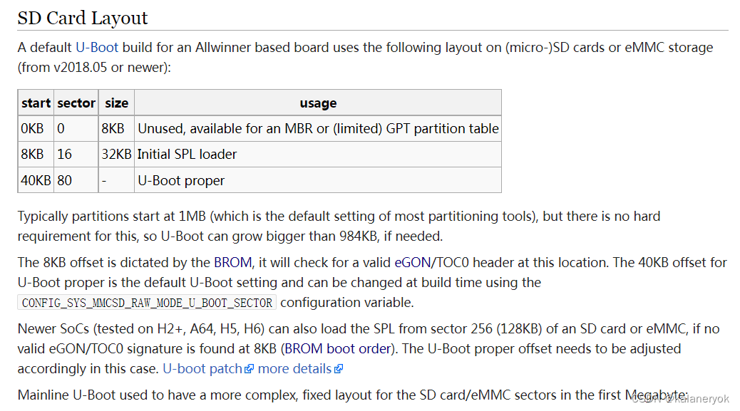
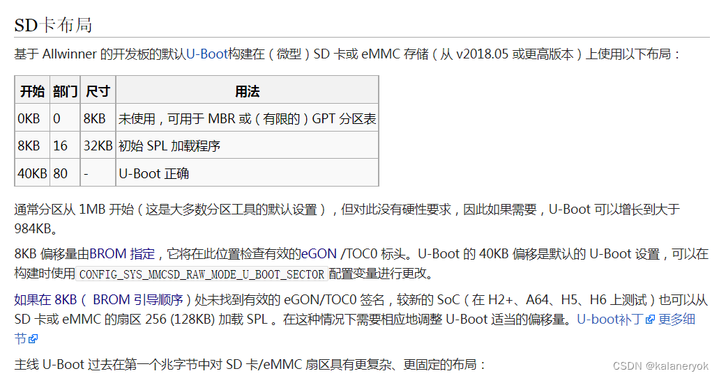
参考文献SD布局
eGON 中对tf的处理
制作镜像
从上面bootrom行为来看他是从8K的地方开始检测boot0。
atf和uboot经过打包成u-boot.itb
u-boot.itb(uboot目录下需要atf文件bl31.bin)这个文件烧写到0x50*512B的地方也就是40KB的位置
操作:
spl 8K /512 == 0x10 16
0x8000 /512 == 0x30
tftp sunxi-spl.bin
mmc write 0x42000000 10 40
tftp u-boot.itb
40K/512 == 0x50
mmc write 0x42000000 50 400
- spl.bin烧写在8KB的地址上
- u-boot.itb烧写在40KB的地址上
上电打印
U-Boot SPL 2018.03 (Jun 26 2022 - 20:31:13 +0800)
DRAM: 1024 MiB
>>spl:board_init_r()
Trying akk to boot from MMC1
spl: bootmomd: 1
os :17
Jumping to U-Boot
SPL malloc() used lx bytes (408 KB)
loaded - jumping to U-Boot...
image entry point: 0x
NOTICE:  BL3-1: Running on H5 (1718) in SRAM A2 (@0x44000)
NOTICE:  Configuring SPC Controller
NOTICE:  BL3-1: v1.0(debug):ae787242
NOTICE:  BL3-1: Built : 20:43:27, Feb 21 2018
NOTICE:  DT: sun50i-h5-orangepi-pc2
NOTICE:  SCPI: dummy stub handler, implementation level: 000000
INFO:    BL3-1: Initializing runtime services
INFO:    BL3-1: Preparing for EL3 exit to normal world
INFO:    BL3-1: Next image address: 0x4a000000, SPSR: 0x3c9


U-Boot 2018.03 (Jun 26 2022 - 20:34:26 +0800) Allwinner Technology

CPU:   Allwinner H5 (SUN50I)
Model: OrangePi PC 2
DRAM:  1 GiB
MMC:   SUNXI SD/MMC: 0
Loading Environment from FAT... Unable to use mmc 0:0... Failed (-5)
Loading Environment from MMC... *** Warning - bad CRC, using default environment

Failed (-5)
In:    serial
Out:   serial
Err:   serial
Net:   phy interface7
eth0: ethernet@1c30000
starting USB...
USB0:   PA: set_value: error: gpio PA0 not reserved
USB EHCI 1.00
USB1:   USB OHCI 1.0
scanning bus 0 for devices... 1 USB Device(s) found
       scanning usb for storage devices... 0 Storage Device(s) found
Hit any key to stop autoboot:  0
AK #
AK #
为什么是40KB这个地址这里解释下,前面分析这个地址应该是spl中去确定的,那么在spl中根据自己的启动介质会执行相对应的load_image函数经过调用分析,mmc(tf卡)他的调用关系是这样的
具体实现是这个文件common/spl/spl_mmc.c
依赖这个宏CONFIG_SYS_MMCSD_RAW_MODE_U_BOOT_SECTOR
这个CONFIG_SYS_MMCSD_RAW_MODE_U_BOOT_SECTOR的值就是0x40,在mmc中一个sector大小512B,那么实际地址就是32K的地方(为啥是32k,不是40k么,后面来解释)
uboot(spl.bin)-》board_init_r->boot_from_devices(确定boot src)-》spl_load_image-(函数指针,不同媒介指向函数不一样)-》tf卡 spl_mmc_load_image-》spl_mmc_load》走的是MMCSD_MODE_RAW
这里就有分支了如果加载os走mmc_load_image_raw_os
如果是有分区的CONFIG_SYS_MMCSD_RAW_MODE_U_BOOT_USE_PARTITION ,走mmc_load_image_raw_partition
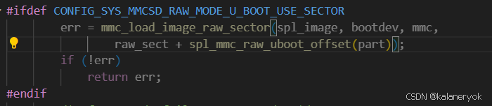
如果CONFIG_SYS_MMCSD_RAW_MODE_U_BOOT_USE_SECTOR,走
mmc_load_image_raw_sector,
我们现在就是走mmc_load_image_raw_sector 函数,
- mmc_load_image_raw_sector:有对镜像的头进行校验check这个头就是mkimage header 64字节
- 其中mmc_load_image_raw_sector的参数有指定其实mmc地址进行镜像读取,他的值就是CONFIG_SYS_MMCSD_RAW_MODE_U_BOOT_USE_SECTOR+ 8k的地址
这里的raw_sect就是i这个U_BOOT_USE_SECTOR为0x40,spl_mmc_raw_uboot_offset返回值其实就是一个宏CONFIG_SYS_MMCSD_RAW_MODE_U_BOOT_DATA_PART_OFFSET(0x10),刚好8k的大小总的算起来就是0x50 * 512 就是40k的地址spl读出uboot正确


 被折叠的 条评论
为什么被折叠?
被折叠的 条评论
为什么被折叠?
 到【灌水乐园】发言


