


 @恋爱交换机HCNA 笔记在空闲的时间里去做的笔记eNSP及VRP基础操作1.1 熟悉VRP基本操作最初配置Sysname //名字修改名字clock datetime 00:00:00 2018-07-28 //设置路由时钟clock timezone BJ add 08:00:00 //设置时区header login information“HELLO” // 设置...
@城建黑师兄
HCNA 笔记
在空闲的时间里去做的笔记
eNSP及VRP基础操作
1.1 熟悉VRP基本操作

最初配置
Sysname  //名字修改名字
clock datetime 00:00:00 2018-07-28  //设置路由时钟
clock timezone BJ add 08:00:00  //设置时区
header login information“HELLO” // 设置标题登录时的信息
header shell information“hello da chen” //设置标题登录后的信息
display version  //查看路由版本信息
display current-configuration //查看路由当前配置
display int g0/0/0(端口号可变)//查看端口信息


最终配置
<R1>display current-configuration
[V200R003C00]
#
 sysname R1
 header shell information "Welcome to Huawei certification lab"
 header login information "hello"
#
 clock timezone BJ add 08:00:00
 clock daylight-saving-time Day Light Saving Time repeating 12:32 9-1 12:32 11-23 00:00 2005 2005
#
interface GigabitEthernet0/0/0
 ip address 10.1.1.1 255.255.255.0
#
Return
1.2熟悉常用的IP相关命令
本实验模拟简单的企业网络场景,某公司购买了新的路由器和交换机。交换机S
连接客服部PC-1,S2连接市场部PC-2,路由器R1连接S1和S2两台交换机。网络管
理员需要首先熟悉设备的使用,包括基础的P配置和查看命令。

最终配置
<R1>display current-configuration
[V200R003C00]
#
 sysname R1
#
interface GigabitEthernet0/0/0
 ip address 10.0.1.254 255.255.255.0
#
interface GigabitEthernet0/0/1
 ip address 10.0.2.254 255.255.255.0
#
return
1.3 配置通过Telnet登录系统
实验内容
本实验模拟公司网络场景。路由器R是公司机房的一台设备,公司员工的办公区
与机房不在同一个楼层,路由器R2和R3模拟员工主机,通过交换机S1与机房设备相
连。为了方便用户的管理,现需要在路由器R1上配置 Telnet使用户能在办公区远程管
理机房设备。为了提高安全性, Telnet需要使用密码认证,只有网络管理员能对设备进行配置和管理,普通用户仅能监控设备

最初配置
Vty视图的
User-interface vty 0 4  //(进入vty模式)
Authentication-mode password  //(验证方式为密码的形式)
Set authentication password cipher Huawei  //(加密的密码,明文密码为 simple)
User privilege level 1  // (级别为0为参观级别,1监控级别, 2为配置级别,3为管理级别)
AAA视图的
Aaa   //(进入aaa 模式)
Local-user admin password cipher huawei privilege level 3  //(命名用户名,配密码,给级别)
Local-user admin service-type Telnet   //(用户接入类型为Telnet)
User-interface vty 0 4  //(进入vty模式改验证模式)
Authentication-mode aaa  //(改为aaa验证)

最终配置
<R1>display current-configuration
#
sysname R1
#
interface GigabitEthernet0/0/0
 ip address 10.1.1.254 255.255.255.0
#
Return

<R2>display current-configuration
#
sysname R2
#
interface Ethernet0/0/0
 ip address 10.1.1.1 255.255.255.0
#
return

<R3>display current-configuration
#
sysname R3
#
interface Ethernet0/0/0
 ip address 10.1.1.2 255.255.255.0
#
return
###1.4 配置通过STelnet登录系统
实验内容
使用路由器R1模拟PC,作为SSH的 Client;路由器R2作为SSH的 Server,模拟
远程用户端R1通过SSH协议远程登录到路由器R2上进行各种配置。本实验将通过Password认证方式来实现

最初配置
R2:
Rsa local-key-pair create  //(生成本地主机秘钥对)
User-interface vty 0 4  //(进入vty模式)
Authentication-mode aaa  //(验证方式为aaa)
Protocol inbound ssh  //(仅支持ssh协议)
Aaa  //(进入aaa 模式)
Local-user huawei password cipher Huawei //(命名用户、给密码)
Local-user huawei service-type ssh  //(配置用户的接入类型为ssh)
Ssh user huawei authentication-type password  //(创建ssh 用户的验证方式为password)
Stelnet server enable  //(开启加密登录服务)
Display rsa local-type-pair public  // (查看本地秘钥中的信息)
Display ssh user-information huawei  //(查看ssh 用户信息/全局配置)display ssh server status
R1
Ssh client first-time enable  //(第一次开启ssh登录服务)
Stelnet IP地址
最终配置
<R1>display current-configuration
sysname R1
#
 set cpu-usage threshold 80 restore 75
#
 rsa peer-public-key 10.1.1.254
  public-key-code begin
   3047
     0240
       B910F7D8 EF50B04E CCF8692A 4F1B3FB3 202C3E66 B6D2C7EB FDBF0909 ED160F5E
       76B5D916 CBB29432 F9044E04 8434B0AB E8FAB968 1672958B F732F788 0DA94F85
     0203
       010001
  public-key-code end
 peer-public-key end
#
interface GigabitEthernet0/0/0
 ip address 10.1.1.1 255.255.255.0
#
 ssh client 10.1.1.254 assign rsa-key 10.1.1.254
 ssh client first-time enable

<R2>display current-configuration
sysname R2
#
aaa
 authentication-scheme default
 authorization-scheme default
 accounting-scheme default
 domain default
 domain default_admin
 local-user admin password cipher %$%$K8m.Nt84DZ}e#<0`8bmE3Uw}%$%$
 local-user admin service-type http
 local-user huawei1 password cipher %$%$cRb~BL,]5D(!v-QiMgd$:RxE%$%$
 local-user huawei1 privilege level 3
 local-user huawei1 service-type ssh
#
interface GigabitEthernet0/0/0
 ip address 10.1.1.254 255.255.255.0
#
stelnet server enable
#
user-interface vty 0 4
 auth
 protocol inbound ssh
1.5 配置通过FTP进行文件操作
实验内容
本实验模拟企业网络,PC1为FP用户端设备,需要访 FTP Server,从服务器上下载或上传文件。出于安全角度考虑,为防止服务器被病毒文件感染,不允许用户端直接上传文件到 Server。网络管理员在R1上设置了限制,使员工不能上传文件到 Server,但是可以从Server下载文件。R1也需要作为用户端从 Server下载更新文件,同时配置R1作为FTP服务器,员工可上传文件到R1上,经过管理员的检测后由R1再上传到 FTP Server

最初配置
在电脑里建一个名为“FTP-Huawei”的文件夹,子文件夹为“config”文件为“test.txt”
在FTP服务器里设置刚才建的文件夹为FTP的文件夹,设置完,启动ftp服务


R1
ftp 10.0.2.1 (R1登录到ftp 服务器)——要给用户名和密码(随便你给)

Ls 查看 ftp 服务器有没有config 文件夹
Cd config  //进入文件夹
Dir  //查看config文件夹属性
Get test.txt  //(从ftp服务器下载到路由器上)
Put test.txt new.txt  //(从路由器上传到FTP服务器上,并且改了名字)
ftp server enable  //(配置路由器为ftp 服务器)
Aaa  //(进入aaa模式)
Local-user ftp password cipher huawei privilege level 15  //(起名字,配密码,给级别)
Local-user ftp ftp-directory flash  //(设置ftp 可访问的目录)
Local-user ftp server-type ftp  //(用户服务类型为ftp)


PC1
服务地址为R1 0/0 端口地址,用户名为ftp,密码为huawei,弄好点登陆,就可以把各盘里点两点小于1M的文件上传到路由上了(1M是对模拟器来说的),再由路由器上传到服务器上

最终配置
<R1>display current-configuration
[V200R003C00]
#
sysname R1
ftp server enable
#
aaa
local-user ftp password cipher %$%$%/xlTEcUeFU_="WB+iPI_n:M%$%$
local-user ftp ftp-directory flash:
local-user ftp service-type ftp
#
interface GigabitEthernet0/0/0
ip address 10.0.1.254 255.255.255.0
#
interface GigabitEthernet0/0/1
ip address 10.0.2.254 255.255.255.0
#
Return
静态路由
2.1 静态路由及默认路由基本配置
在由3台路由器组成的简单网络中,R1与R3各自连接着一台主机,现在要求能够实现主机PC1与PC2之间的正常通信。本实验通过配置基本的静态路由和默

初始化
R1:
sys
sysname R1
int e0/0/0
ip add 192.168.10.254 24
int s0/0/0
ip add 10.0.12.1 24
q

R2:
sys
sysname R2
int s0/0/1
ip add 10.0.12.2 24
int s0/0/0
ip add 10.0.23.2 24
q

R3:
sys
sysname R3
int s0/0/1
ip add 10.0.23.3 24
int e0/0/0
ip add 192.168.20.254 24
q

实现PC1和PC2之间的通信
R1
ip route-static 192.168.20.0 255.255.255.0 10.0.12.2
ip route-static 10.0.23.0 255.255.255.0 10.0.12.2           //外人的

R2
ip route-static 192.168.10.0 255.255.255.0 10.0.12.1
ip route-static 192.168.20.0 255.255.255.0 10.0.23.3

R3
ip route-static 192.168.10.0 24 10.0.23.2
ip route-static 10.0.12.0 24 10.0.23.2

最终配置
<R1>display current-configuration
#
sysname R1
#
interface Ethernet0/0/0
 ip address 192.168.10.1 255.255.255.0
#
interface Serial0/0/0
 link-protocol ppp
 ip address 10.0.12.1 255.255.255.0
#
ip route-static 0.0.0.0 0.0.0.0 10.0.12.2
#
Return

<R2>display current-configuration
#
sysname R2
#
interface Serial0/0/0
 link-protocol ppp
 ip address 10.0.23.2 255.255.255.0
#
interface Serial0/0/1
 link-protocol ppp
 ip address 10.0.12.2 255.255.255.0
#
ip route-static 192.168.10.0 255.255.255.0 Serial0/0/1
ip route-static 192.168.20.0 255.255.255.0 10.0.23.3
#
Return

<R3>display current-configuration
#
sysname R3
#
interface Ethernet0/0/0
 ip address 192.168.20.3 255.255.255.0
#
interface Serial0/0/1
 link-protocol ppp
 ip address 10.0.23.3 255.255.255.0
#
ip route-static 0.0.0.0 0.0.0.0 Serial0/0/1
#
Return
2.2 浮动静态路由及负载均衡
R2为某公司总部,R1与R3是两个分部,主机PC1与PC2所在的分别模拟两个分部中的办公网络。现需总部与各个分部,分部与分部之间都能够通信,且分部之间在通信时,之间直连链路为主用链路,通过总部的主用链路为备用链路。本实验使用浮动静态路由实现要求,并且根据需求来实现负载均衡来优化网络。

初始化
R1:
sys
sysname R1
int g0/0/0
ip add 192.168.10.1 24
int s1/0/0
ip add 10.0.12.1 24
int s1/0/1
ip add 10.0.13.1 24
q
ip route-static 192.168.20.0 255.255.255.0 10.0.13.3

R2:
sys
sysname R2
int s1/0/0
ip add 10.0.12.2 24
int s1/0/1
ip add 10.0.23.2 24
q
ip route-static 192.168.10.0 24 10.0.12.1
ip route-static 192.168.20.0 24 10.0.23.3

R3:
sys
sysname R3
int g0/0/0
ip add 192.168.20.1 24
int s1/0/0
ip add 10.0.23.3 24
int s1/0/1
ip add 10.0.13.3 24
q
ip route-static 192.168.10.0 24 10.0.13.1

配置浮动静态路由实现路由备份
R1:
ip route-static 192.168.20.0 24 10.0.12.2 preference 100  //(默认60,优先值越高越优低)

R3:
ip route-static 192.168.10.0 24 10.0.23.2 preference 100

查看路由命令dis ip routing-table无法查看到备份路由
要使用命令dis ip routing-table protocol static命令仅查看静态路由可看到

配置负载均衡(2条路由的优先级一样即可)(恢复R1和R3的浮动静态路由的优先级
)
R1:
ip route-static 192.168.20.0 24 10.0.12.2

R3:
ip route-static 192.168.10.0 24 10.0.23.2
最终配置
<R1>display current-configuration
#
sysname R1
#
interface GigabitEthernet0/0/0
 ip address 192.168.10.1 255.255.255.0
#
interface Serial1/0/0
 link-protocol ppp
 ip address 10.1.12.1 255.255.255.0
#
interface Serial1/0/1
 link-protocol ppp
 ip address 10.1.13.1 255.255.255.0
#
ip route-static 192.168.20.0 255.255.255.0 10.1.13.3
ip route-static 192.168.20.0 255.255.255.0 10.1.12.2
#
Return

<R2>display current-configuration
#
sysname R2
#
interface Serial1/0/0
 link-protocol ppp
 ip address 10.1.12.2 255.255.255.0
#
interface Serial1/0/1
 link-protocol ppp
 ip address 10.1.23.2 255.255.255.0
#
ip route-static 192.168.10.0 255.255.255.0 10.1.12.1
ip route-static 192.168.20.0 255.255.255.0 10.1.23.3
#
Return

<R3>display current-configuration
#
sysname R3
#
interface GigabitEthernet0/0/0
 ip address 192.168.20.1 255.255.255.0
#
interface Serial1/0/0
 link-protocol ppp
 ip address 10.1.23.3 255.255.255.0
#
interface Serial1/0/1
 link-protocol ppp
 ip address 10.1.13.3 255.255.255.0
#
ip route-static 192.168.10.0 255.255.255.0 10.1.13.1
ip route-static 192.168.10.0 255.255.255.0 10.1.23.2
#
Return
RIP
3.1 RIP路由协议基本配置


初始化:
R1:
sys
sysname R1
int e0/0/0
ip add 10.0.12.1 24
int loopback 0
ip add 10.0.1.1 24
q

R2:
sys
sysname R2
int e0/0/0
ip add 10.0.12.2 24
int loopback 0
ip add 10.0.2.2 24
q

使用RIPv1搭建网络
R1,R2:
rip
network 10.0.0.0

dis ip routing-table

<>debugging rip 1
dis debugging
terminal debugging
terminal monitor debug

undo debugging rip 1
或undo debugging all

debugging rip 1 event

使用RIPv2搭建网络

最终配置
<R1>display current-configuration
#
sysname R1
#
interface Ethernet0/0/0
 ip address 10.0.12.1 255.255.255.0
#
interface LoopBack0
 ip address 10.0.1.1 255.255.255.0
#
rip 1
 version 2
 network 10.0.0.0
#
return

<R2>display current-configuration
#
sysname R2
#
interface Ethernet0/0/0
 ip address 10.0.12.2 255.255.255.0
#
interface LoopBack0
 ip address 10.0.2.2 255.255.255.0
#
rip 1
 version 2
 network 10.0.0.0
#
return
3.2 配置RIPv2的认证


初始化:
R1:
sys
sysname R1
int g0/0/0
ip add 192.168.10.1 24
int g0/0/1
ip add 10.0.12.1 24
q

R2:
sys
sysname R2
int g0/0/0
ip add 192.168.20.1 24
int g0/0/1
ip add 10.0.12.2 24
q

R3:
sys
sysname R3
int g0/0/0
ip add 10.0.12.3 24
int loopback 0
ip add 192.168.10.1 24
int loopback 1
ip add 192.168.20.1 24
q

搭建RIP网络
R1:
rip
version 2
network 192.168.10.0
network 10.0.0.0
q

R2:
rip
version 2
network 192.168.20.0
network 10.0.0.0
q

dis ip routing-table

模拟R3网络攻击
R3:
rip
version 2
network 10.0.0.0
dis ip routing-table
rip
version 2
network 192.168.10.0
network 192.168.20.0
q
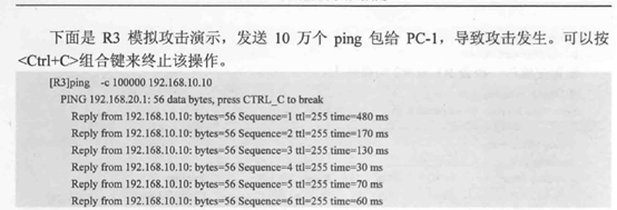
发送大量的数据包进行攻击(占用带宽,降低网速)
配置RIPv2简单验证
R1:
int g0/0/1
rip authentication-mode simple huawei
q

R2:
int g0/0/1
rip authentication-mode simple huawei
q

配置RIPv2 MD5密文验证
R1:
int g0/0/1
undo rip authentication-mode  // 去掉简单认证功能
rip authentication-mode md5 usual Huawei  //开启MD5模式
q

R2:
int g0/0/1
undo rip authentication-mode   去掉简单认证功能

rip authentication-mode md5 usual huawei
q

使用如下命令清除R3在密码错误之前从R2学到的路由信息
<R3> reset ip routing-table statistics protocol rip
最终配置
<R1>display current-configuration
#
sysname R1
#
interface GigabitEthernet0/0/0
ip address 192.168.10.1 255.255.255.0
#
interface GigabitEthernet0/0/1
link-protocolppp
ip address 10.0.12.1 255.255.255.0
rip authentication-mode md5 nonstandard $GOOD_=eh*)f8\~B3e~&Z5%# 1
#
rip 1
version 2
network 192.168.10.0
network 10.0.0.0
#
return

<R2>display current-configuration
#
sysname R2
#
interface GigabitEthernet0/0/0
ip address 192.168.20.1 255.255.255.0
#
interface GigabitEthernet0/0/1
link-protocolppp
ip address 10.0.12.2 255.255.255.0
rip authentication-mode md5 nonstandard &-nhYkNR4BC,%TLlYj-OAF@#
#
rip 1
version 2
network 192.168.20.0
network 10.0.0.0
#
return

<R3>display current-configuration
#
sysname R3
#
Interface loopback0
ip address 192.168.10.10 255.255.255.0
#
Interface loopback1
ip address 192.168.20.20 255.255.255.0
#
interface GigabitEthernet0/0/1
link-protocolppp
ip address 10.0.12.1 255.255.255.0
rip authentication-mode md5 nonstandard $GOOD_=eh*)f8\~B3e~&Z5%# 1
#
rip 1
version 2
network 192.168.10.0
network 192.168.20.0
network 10.0.0.0
#
Return
3.3 RIP路由协议的汇总

初始化:
R1:
sys
sysname R1
int s1/0/0
ip add 192.168.12.1 24
q

R2:
sys
sysname R2
int s1/0/1
ip add 192.168.12.2 24
int s1/0/0
ip add 192.168.23.2 24
q

R3:
sys
sysname R3
int s1/0/1
ip add 192.168.23.3 24
int loopback 0
ip add 3.3.0.3 24
int loopback 1
ip add 3.3.1.3 24
int loopback 2
ip add 3.3.2.3 24
int loopback 3
ip add 3.3.3.3 24
q

配置RIPv1
R1:
rip 1
network 192.168.12.0

R2:
rip 1
network 192.168.12.0
network 192.168.23.0

R3:
rip 1
network 192.168.23.0
network 3.0.0.0

dis default-parameter rip

配置RIPv2自动汇总
R1,R2,R3
rip 1
version 2

rip 1
summary always  // 使自动汇总生效
或
int s1/0/1
undo rip split-horizon
q

配置RIPv2手动汇总
R3:
int s1/0/1
rip summary-address 3.3.0.0 255.255.252.0
q


在路由出接口上配置汇总路由
int g0/0/0
rip summary-address 172.16.0.0 255.255.0.0
最终配置
<R1>display current-configuration
#
sysname R1
#
interface Serial0/0/0
 link-protocol ppp
 ip address 192.168.12.1 255.255.255.0
#
rip 1
 version 2
 network 192.168.12.0
#
return

<R2>display current-configuration
#
sysname R2
#
interface Serial0/0/0
 link-protocol ppp
 ip address 192.168.23.2 255.255.255.0
#
interface Serial0/0/1
 link-protocol ppp
 ip address 192.168.12.2 255.255.255.0
#
rip 1
 version 2
 network 192.168.12.0
 network 192.168.23.0
#
return

<R3>display current-configuration
#
sysname R3
#
interface Serial0/0/1
 link-protocol ppp
 ip address 192.168.23.3 255.255.255.0
 rip summary-address 3.3.0.0 255.255.252.0
#
interface LoopBack0
 ip address 3.3.0.3 255.255.255.0
#
interface LoopBack1
 ip address 3.3.1.3 255.255.255.0
#
interface LoopBack2
 ip address 3.3.2.3 255.255.255.0
#
interface LoopBack3
 ip address 3.3.3.3 255.255.255.0
#
rip 1
 undo summary
 version 2
 network 192.168.23.0
 network 3.0.0.0
#
return
3.4 配置RIP的版本兼容、定时器及协议优先级

初始化:
R1:
sys
sysname R1
int g0/0/1
ip add 192.168.10.1 24
int g0/0/0
ip add 10.0.12.1 24
q
rip 1
network 192.168.10.0
network 10.0.0.0
q

R2:
sys
sysname R2
int g0/0/1
ip add 192.168.20.1 24
int g0/0/0
ip add 10.0.12.2 24
q
rip 1
version 2
network 192.168.20.0
network 10.0.0.0
q

R1:
int g0/0/0
rip version 2 broadcast/multicast   // 开启R1发送V2报文

int g0/0/0
undo rip output   //停止发送路由更新

R2
dis ip routing-table  //更新数据库
dis rip 1 database

rip
preference 90    //优先值越小,代表优先级越高

rip
timers rip 20 120 60  //报文更新时间为20秒,超时时间为120秒,垃圾收集60秒。
q
dis rip


最终配置
<R1>display current-configuration
#
sysname R1
#
interface GigabitEthernet0/0/0
 ip address 10.0.12.1 255.255.255.0
#
interface GigabitEthernet0/0/1
 ip address 192.168.10.1 255.255.255.0
#
rip 1
 version 2
 network 10.0.0.0
 network 192.168.10.0
preference 90
 timers rip 20 120 60
#
return

<R2>display current-configuration
#
sysname R2
#
interface GigabitEthernet0/0/0
 ip address 10.0.12.2 255.255.255.0
#
interface GigabitEthernet0/0/1
 ip address 192.168.20.1 255.255.255.0
#
rip 1
 version 2
 network 10.0.0.0
 network 192.168.20.0
#
return
3.5 配置RIP抑制接口及单播更新


初始化:
R1:
sys
sysname R1
int g0/0/1
ip add 172.16.1.254 24
q
rip
network 172.16.0.0
q

R2:
sys
sysname R2
int e1/0/1
ip add 172.16.1.100 24
int e1/0/0
ip add 172.16.2.254 24
q
rip
network 172.16.0.0
q

R3:
sys
sysname R3
int e1/0/1
ip add 172.16.1.200 24
int e1/0/0
ip add 192.168.1.254 24
q

配置RIP抑制接口
R1:
rip
silent-int g0/0/1  //抑制接口不接受不发生报文(不更新报文),有效的控制环路问题,但是不能访问内网和外网

R2:
rip
silent-int e1/0/1
silent-int e1/0/0

R3:
rip
silent-int e1/0/1
silent-int e1/0/0

dis rip

配置RIP单播更新
R1:
rip
peer 172.16.1.100   //配置邻居路由
peer 172.16.1.200
q

R2:
rip
peer 172.16.1.254
peer 172.16.1.200
q

R3:
rip
peer 172.16.1.254
peer 172.16.1.100
q


法二:
rip 1
undo silent-int g0/0/1  //去掉之前的功能
undo peer 172.16.1.100
undo peer 172.16.1.200
int g0/0/1  //进入配置接口
undo rip output  //路由信息不更新出去,别人访问不了
peer 172.16.1.100  //为了能访问这个地址
peer 172.16.1.200
peer 172.16.1.254  //为了能访问外网

最终配置
<R1>display current-configuration
#
sysname R1
#
interface GigabitEthernet0/0/1
 ip address 172.16.1.254 255.255.255.0
#
rip 1
 peer 172.16.1.100
 peer 172.16.1.200
 network 172.16.0.0
 silent-interface GigabitEthernet0/0/1
#
Return

<R2>display current-configuration
#
sysname R2
#
interface Ethernet1/0/1
 ip address 172.16.1.100 255.255.255.0
#
interface Ethernet1/0/0
 ip address 172.16.2.254 255.255.255.0
#
rip 1
 peer 172.16.1.254
 peer 172.16.1.200
 network 172.16.0.0
 silent-interface Ethernet1/0/0
 silent-interface Ethernet1/0/1
#
Return

<R3>display current-configuration
#
sysname R3
#
interface Ethernet1/0/1
 ip address 172.16.1.200 255.255.255.0
 undo rip output
#
interface Ethernet1/0/0
 ip address 192.168.1.254 255.255.255.0
#
rip 1
 peer 172.16.1.254
 network 172.16.0.0
 network 192.168.1.0
#
return
3.6 RIP与不连续子网


初始化:
R1:
sys
sysname R1
int e1/0/0
ip add  10.0.12.1 24
q
rip
network 10.0.0.0
q

R2:
sys
sysname R2
int e1/0/0
ip add 10.0.12.2 24
int s2/0/0
ip add 192.168.23.2 24
q
rip
network 10.0.0.0
network 192.168.23.0
q

R3:
sys
sysname R3
int s1/0/0
ip add  192.168.23.3 24
int s1/0/1
ip add  192.168.34.3 24
q
rip
network 192.168.23.0
network 192.168.34.0
q

R4:
sys
sysname R4
int s2/0/1
ip add  192.168.34.4 24
int e1/0/0
ip add  10.0.45.4 24
q
rip
network 192.168.34.0
network 10.0.0.0
q

R5:
sys
sysname R5
int e1/0/0
ip add 10.0.45.5 24
q
rip
network 10.0.0.0
q

[R1]ping 10.0.12.2
[R1]dis ip routing-table 或
[R1]dis ip routing-table protocol rip
[R2]dis ip routing-table
[R3]dis ip routing-table

[R3]ping 10.0.45.5
[R3]ping 10.0.12.1

RIPv1中解决不连续子网问题
R2:
int s2/0/0
ip add 10.0.23.2 24 sub
q

R3:
int s1/0/0
ip add 10.0.23.3 24 sub
int s1/0/1
ip add 10.0.34.3 24 sub
q
rip
network 10.0.0.0
q

R4:
int s2/0/1
ip add 10.0.34.4 24 sub
q

[R1][R2][R3]dis ip routing-table

RIPv2中解决不连续子网问题   直接关掉自动汇总
R1:
rip
version 2
undo summary
q

R2:
int s2/0/0
undo ip add 10.0.23.2 24 sub
rip
version 2
undo summary
q

R3:
int s1/0/0
undo ip add 10.0.23.3 24 sub
int s1/0/1
undo ip add 10.0.34.3 24 sub
rip
version 2
undo summary
q

R4:
int s2/0/1
undo ip add 10.0.34.4 24 sub
rip
version 2
undo summary
q

R1-5
dis ip routing-table

[R1]ping 10.0.45.5
最终配置
<R1>display current-configuration
#
interface Ethernet0/0/0
 ip address 10.0.12.1 255.255.255.0
#
rip 1
 undo summary
 version 2
 network 10.0.0.0
#

<R2> display current-configuration
#
sysname R2
#
interface Ethernet0/0/0
 ip address 10.0.12.2 255.255.255.0
#
interface Serial0/0/0
 link-protocol ppp
 ip address 192.168.23.2 255.255.255.0
#
rip 1
 undo summary
 version 2
 network 10.0.0.0
 network 192.168.23.0
#

<R3>display current-configuration
#
sysname R3
#
interface Serial0/0/0
 link-protocol ppp
 ip address 192.168.23.3 255.255.255.0
#
interface Serial0/0/1
 link-protocol ppp
 ip address 192.168.34.3 255.255.255.0
#
rip 1
 undo summary
 version 2
 network 192.168.23.0
 network 192.168.34.0
#

<R4>display current-configuration
#
sysname R4
interface Ethernet0/0/0
 ip address 10.0.45.4 255.255.255.0
interface Serial0/0/1
 link-protocol ppp
 ip address 192.168.34.4 255.255.255.0
#
rip 1
 undo summary
 version 2
 network 192.168.34.0
 network 10.0.0.0

<R5>display current-configuration
#
sysname R5
#
interface Ethernet0/0/0
 ip address 10.0.45.5 255.255.255.0
#
rip 1
 undo summary
 version 2
 network 10.0.0.0
#
3.7 RIP的水平分割及触发更新


初始化:
R1:
sys
sysname R1
int g0/0/0
ip add 172.16.1.1 24
int g0/0/2
ip add 172.16.2.1 24
q
rip
version 2
network 172.16.0.0
q

R2:
sys
sysname R2
int g0/0/1
ip add 172.16.2.2 24
int e1/0/0
ip add 192.168.2.254 24
q
rip
version 2
network 172.16.0.0
network 192.168.2.0
q

R3:
sys
sysname R3
int g0/0/1
ip add 172.16.1.2 24
int e1/0/0
ip add 192.168.1.254 24
q
rip
version 2
network 172.16.0.0
network 192.168.1.0
q

[R1]dis ip routing-table


验证触发更新:

180s //老化计时器过后
R2: dis ip routing-table

验证水平
最低0.47元/天 解锁文章


 137
137


 被折叠的 条评论
为什么被折叠?
被折叠的 条评论
为什么被折叠?
 到【灌水乐园】发言


