


基于EBAZ4205矿板的图像处理:11阈值系数可调的图像局部阈值二值化
先看效果
还是一样拿我的pynq当模特,然后用usb——HDMI采集卡把输出图像采集到电脑上。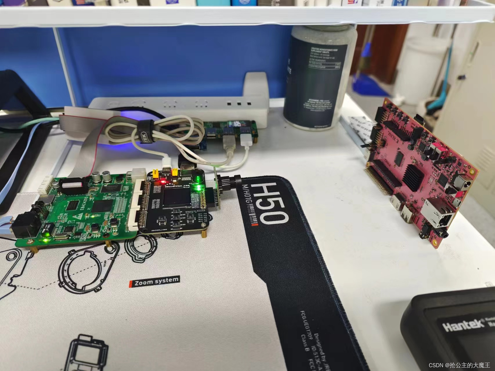
注意看右边mobelxtem中的通过串口调节的参数,
我这里是实现了阈值系数可调的局部阈值二值化,
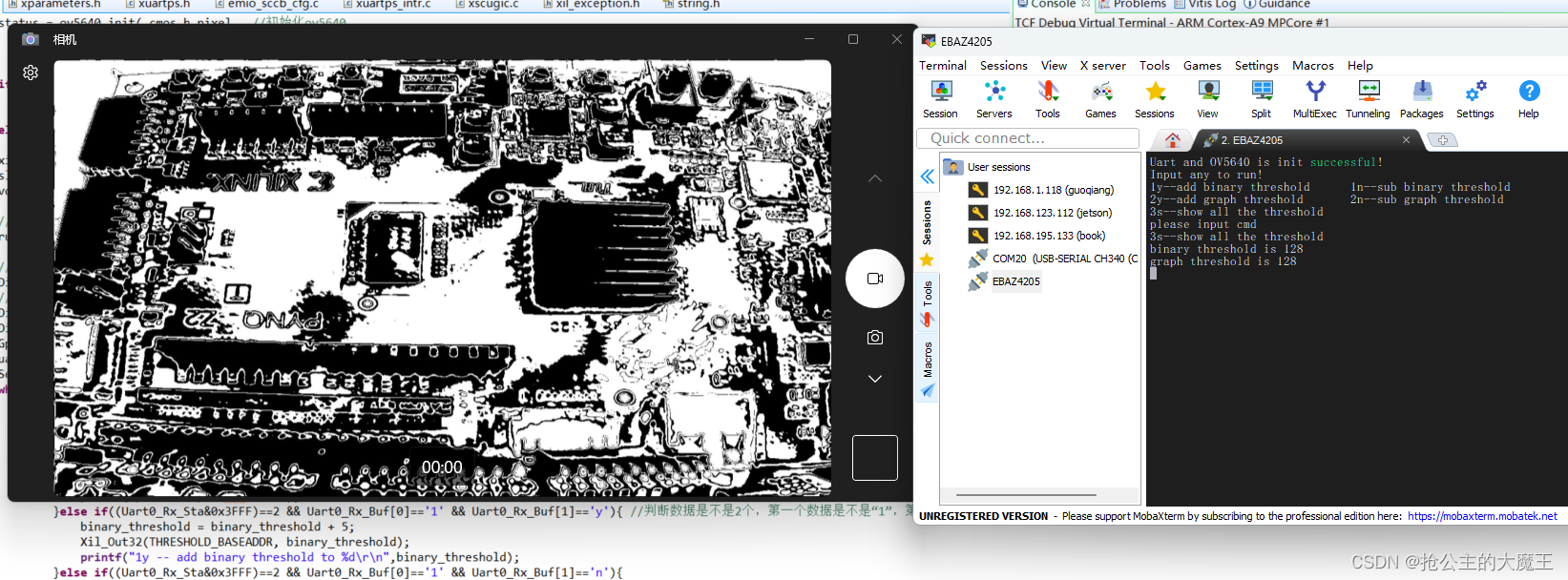
局部阈值二值化系数binary_threshold = 128时的效果
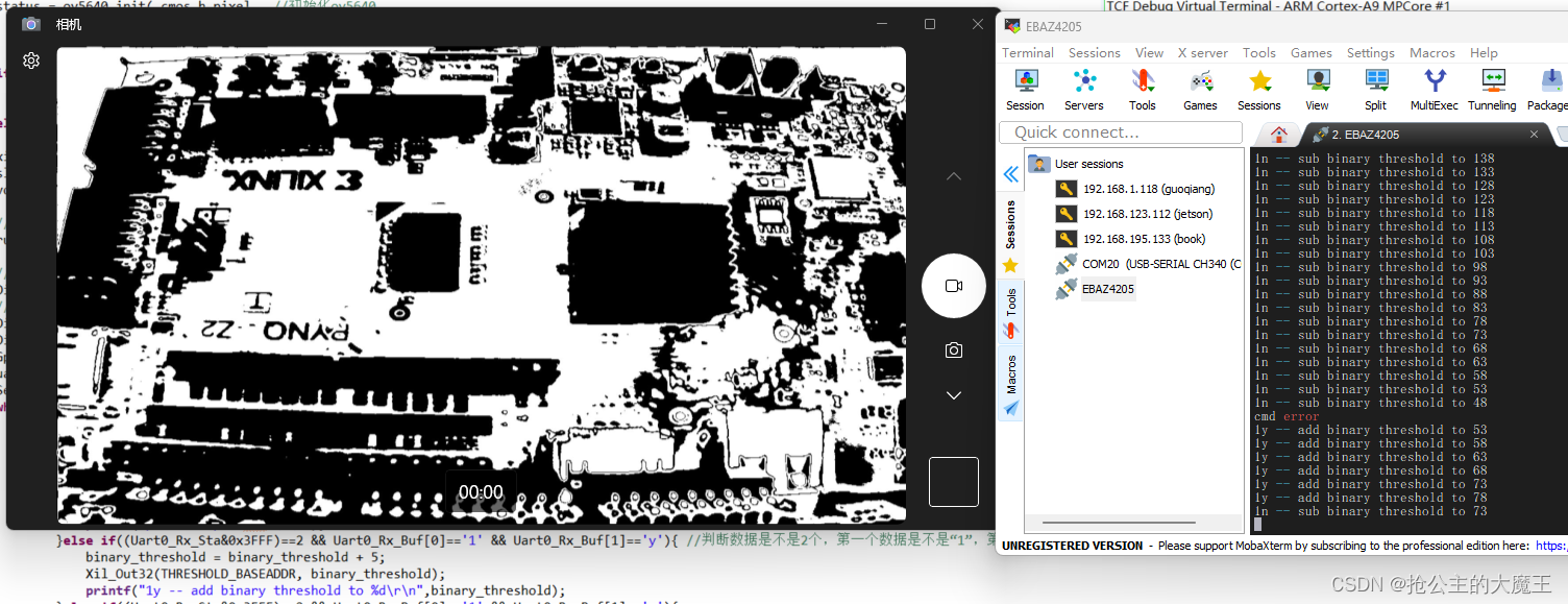
局部阈值二值化系数binary_threshold =73时的效果,个人感觉这个时候效果最好
局部阈值二值化系数binary_threshold = 188时的效果
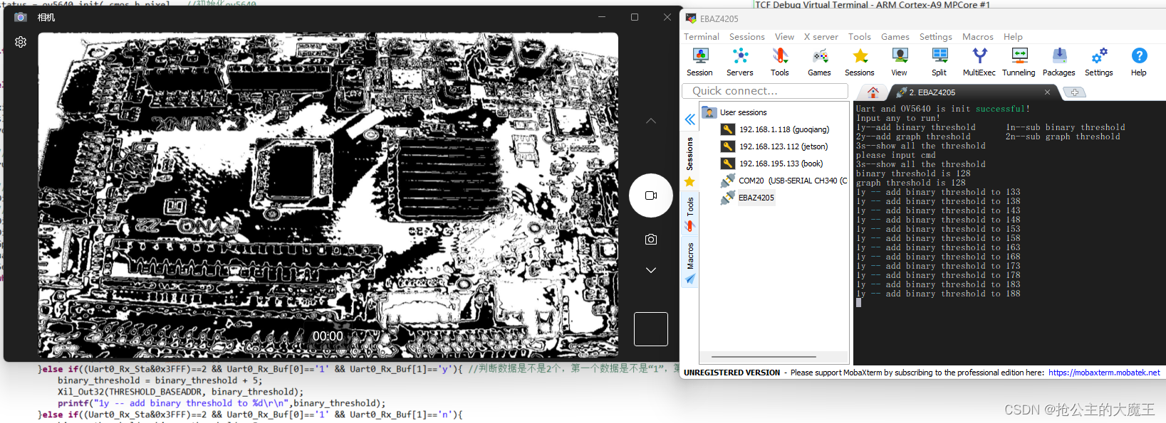
graph_threshold 不用管,那是为了后续的膨胀和腐蚀算法准备的。
算法讲解
图像局部阈值二值化,是一种能够自适应地提取图像局部二值化阈值的方法,他在图像明暗变化不一致的场景下,仍能获得很好的效果。
这种自适应地提取局部(即卷积的滑动窗口)阈值的提取方式有最大类间差,中值提取,均值提取等。
均值提取指的是当一个滑动窗口的中心点像素的像素值大于那个滑动窗口的均值时,将该像素点的像素值置为255,否则置为0。
然后,我在上面均值提取的基础上,在这个“均值”上加了一个调整系数,让一个像素点的最终二值化输出的结果既受到他周围的像素点的影响,也受到我的阈值系数的影响,以此我们就能动态调整图像的二值化效果。
算法的FPGA部署
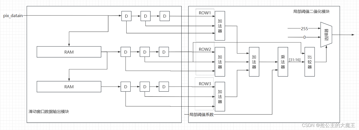
部署流程如上图所示,用两个ram缓存两行数据,然后和第三行实时数据一起通过打三拍地形式,以一种步长为1的滑动窗口的形式输出,将数据矩阵输入到局部阈值二值化模块中通过滑动窗口的均值和局部阈值系数,来对滑动窗口中心点像素进行判断,对滑动窗口中心点进行二值化处理。
项目讲解
block design跟上一篇有一个不同之处在于我添加了一个通过axi lite总线读写pl端reg的ip核,我在这个系列的第10篇博客里详细讲了怎么创建这个IP核。只需要按照那篇博客创建就可以了。
项目block design 如下

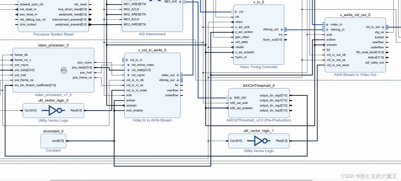
我的AXI Lite读写PLreg的模块,我把四个reg都引出了,方便以后开发。
项目代码
视频流处理模块
//作者:抢公主的大魔王
//日期:24.5.15
module video_processor(
    (* X_INTERFACE_IGNORE = "true" *) input         frame_clk,    //cmos 像素时钟
    (* X_INTERFACE_IGNORE = "true" *) input         frame_rst_n,

    //预处理图像
    (* X_INTERFACE_IGNORE = "true" *) input         pre_vsync, //预处理图像场同步信号
    (* X_INTERFACE_IGNORE = "true" *) input [23:0]  pre_data,  //预处理图像数据
    (* X_INTERFACE_IGNORE = "true" *) input         pre_href,  //预处理图像数据有效信号
    (* X_INTERFACE_IGNORE = "true" *) input         pre_frame_ce, //预处理图像时钟使能信号

    //阈值控制
    (* X_INTERFACE_IGNORE = "true" *) input [7:0 ]  loc_bin_thresh_coefficient, //来自PS端的局部二值化阈值系数


    //处理后图像
    (* X_INTERFACE_IGNORE = "true" *) output        pos_vsync, //处理后图像场同步信号
    (* X_INTERFACE_IGNORE = "true" *) output [23:0] pos_data,  //处理后图像数据
    (* X_INTERFACE_IGNORE = "true" *) output        pos_href, //处理后图像数据有效信号
    (* X_INTERFACE_IGNORE = "true" *) output        pos_frame_ce //处理后图像时钟使能信号
);

//wire define
wire [7:0] gray_data ;
wire       gray_vsync;
wire       gray_frame_ce;
wire       gray_href;

//*****************************************************
//**                    main code
//*****************************************************
//rgb转ycbcr模块
rgb2gray  u_rgb2gray(
    .cmos_frame_clk     (frame_clk      ),
    .cmos_rstn          (frame_rst_n    ),//同步复位
    .cmos_frame_vsync   (pre_vsync      ),
    .cmos_frame_data    (pre_data       ),
    .cmos_frame_href    (pre_href       ),
    .cmos_frame_ce      (pre_frame_ce   ),

    .dataout_frame_vsync(gray_vsync     ),
    .dataout_frame_data (gray_data      ),
    .dataout_frame_href (gray_href      ),
    .dataout_frame_ce   (gray_frame_ce  )
);
//wire define
wire        matrix_frame_vsync;
wire        matrix_frame_href;
wire        matrix_frame_ce;
wire [7:0]  matrix_p11; //3X3 矩阵数据
wire [7:0]  matrix_p12;
wire [7:0]  matrix_p13;
wire [7:0]  matrix_p21;
wire [7:0]  matrix_p22;
wire [7:0]  matrix_p23;
wire [7:0]  matrix_p31;
wire [7:0]  matrix_p32;
wire [7:0]  matrix_p33;
// wire [7:0]  mid_value ;
// wire [7:0]  pos_img_Y;

//*****************************************************
//**                    main code
//*****************************************************

// assign pos_img_Y = pos_gray_href ? mid_value : 8'd0;
// assign pos_pixel_data = {pos_img_Y,pos_img_Y,pos_img_Y};

 VIP_matrix_generate_3x3_8bit u_VIP_matrix_generate_3x3_8bit(
    .clk                (frame_clk      ),
    .rst_n              (frame_rst_n    ),
    .per_frame_vsync    (gray_vsync     ),
    .per_frame_href     (gray_href      ),
    .per_frame_ce       (gray_frame_ce      ),
    .per_img_Y          (gray_data  ),

    //输出3x3矩阵
    .matrix_frame_vsync (matrix_frame_vsync ),
    .matrix_frame_href  (matrix_frame_href  ),
    .matrix_frame_ce    (matrix_frame_ce    ),
    .matrix_p11         (matrix_p11),
    .matrix_p12         (matrix_p12),
    .matrix_p13         (matrix_p13),
    .matrix_p21         (matrix_p21),
    .matrix_p22         (matrix_p22),
    .matrix_p23         (matrix_p23),
    .matrix_p31         (matrix_p31),
    .matrix_p32         (matrix_p32),
    .matrix_p33         (matrix_p33)
);
region_binary   u_region_binary(
    .clk                     (frame_clk             ),
    .rst_n                   (frame_rst_n           ),
    .matrix_img_vsync        (matrix_frame_vsync    ),
    .matrix_img_href         (matrix_frame_href     ),
    .matrix_frame_ce         (matrix_frame_ce       ),
    .loc_bin_thresh_coefficient           (loc_bin_thresh_coefficient         ),
    .matrix_p11              (matrix_p11            ),
    .matrix_p12              (matrix_p12            ),
    .matrix_p13              (matrix_p13            ),
    .matrix_p21              (matrix_p21            ),
    .matrix_p22              (matrix_p22            ),
    .matrix_p23              (matrix_p23            ),
    .matrix_p31              (matrix_p31            ),
    .matrix_p32              (matrix_p32            ),
    .matrix_p33              (matrix_p33            ),
    .dataout_vsync           (pos_vsync             ),       //  processed Image data vsync valid signal
    .dataout_href            (pos_href              ),       //  processed Image data href vaild  signal
    .dataout_gray            (pos_data              ),          //  processed Image brightness output
    .dataout_frame_ce        (pos_frame_ce          ));
endmodule
rgb565转gray模块
`timescale 1ns / 1ps
//作者:抢公主的大魔王
module rgb2gray(

(* X_INTERFACE_IGNORE = "true" *)  input           cmos_frame_vsync,
(* X_INTERFACE_IGNORE = "true" *)  input [23:0]    cmos_frame_data,
(* X_INTERFACE_IGNORE = "true" *)  input           cmos_frame_href,

(* X_INTERFACE_IGNORE = "true" *)  input           cmos_frame_clk,
(* X_INTERFACE_IGNORE = "true" *)  input           cmos_rstn,//同步复位
(* X_INTERFACE_IGNORE = "true" *)  input           cmos_frame_ce,

(* X_INTERFACE_IGNORE = "true" *)  output          dataout_frame_vsync,
(* X_INTERFACE_IGNORE = "true" *)  output [7:0]    dataout_frame_data,
// (* X_INTERFACE_IGNORE = "true" *)  output [23:0]    dataout_frame_data,
(* X_INTERFACE_IGNORE = "true" *)  output          dataout_frame_href,
(* X_INTERFACE_IGNORE = "true" *)  output          dataout_frame_ce
    );
    // Y = 0.299R +0.587G + 0.114B
    // Y = (77 *R + 150*G + 29 *B)>>8
    reg [15:0] r_gray1;
    reg [15:0] g_gray1;
    reg [15:0] b_gray1;
    reg [15:0] y1;
    reg [7:0] y2;
    reg [2:0] dataout_frame_vsync_r;
    reg [2:0] dataout_frame_href_r;
    reg [2:0] dataout_frame_ce_r;


    always@(posedge cmos_frame_clk)begin
        if(!cmos_rstn)begin
            r_gray1 <= 8'h00;
            g_gray1 <= 8'h00;
            b_gray1 <= 8'h00;
        end
        else begin
            r_gray1 <= cmos_frame_data[23:16]  * 8'd77 ;
            g_gray1 <= cmos_frame_data[15:8]   * 8'd150;
            b_gray1 <= cmos_frame_data[7:0]    * 8'd29 ;
        end
    end

    always@(posedge cmos_frame_clk)begin
        if(!cmos_rstn)begin
            y1 <= 16'h0000;
        end
        else begin
            y1 <= r_gray1 + g_gray1 + b_gray1;
        end
    end

    always@(posedge cmos_frame_clk)begin
        if(!cmos_rstn)begin
            y2 <= 8'h0000;
        end
        else begin
            y2 <= y1[15:8];
        end
    end


    always@(posedge cmos_frame_clk)begin
        if(!cmos_rstn)begin
            dataout_frame_ce_r      <= 3'b000;
            dataout_frame_vsync_r   <= 3'b000;
            dataout_frame_href_r    <= 3'b000;
        end
        else begin
            dataout_frame_ce_r      <= {dataout_frame_ce_r[1:0]     ,cmos_frame_ce};
            dataout_frame_vsync_r   <= {dataout_frame_vsync_r[1:0]  ,cmos_frame_vsync};
            dataout_frame_href_r    <= {dataout_frame_href_r[1:0]   ,cmos_frame_href};
        end
    end
    // assign dataout_frame_data = {y2,y2,y2};
    assign dataout_frame_data = y2;
    assign dataout_frame_ce = dataout_frame_ce_r[2];
    assign dataout_frame_vsync = dataout_frame_vsync_r[2];
    assign dataout_frame_href = dataout_frame_href_r[2];


endmodule
卷积矩阵数据生成模块
这个模块和下面的行数据缓冲输出模块不是我写的,然后注意下面的行数据缓冲输出模块,有一个地方要改,我会说明。
//****************************************Copyright (c)***********************************//
//技术支持:www.openedv.com
//淘宝店铺:http://openedv.taobao.com
//关注微信公众平台微信号:"正点原子",免费获取FPGA & STM32资料。
//版权所有,盗版必究。
//Copyright(C) 正点原子 2018-2028
//All rights reserved
//----------------------------------------------------------------------------------------
// File name:           VIP_matrix_generate_3x3_8bit
// Last modified Date:  2019/7/19 10:55:56
// Last Version:        V1.0
// Descriptions:        VIP_matrix_generate_3x3_8bit
//----------------------------------------------------------------------------------------
// Created by:          正点原子
// Created date:        2019/7/19 10:55:56
// Version:             V1.0
// Descriptions:        The original version
//----------------------------------------------------------------------------------------
//****************************************************************************************//

module  VIP_matrix_generate_3x3_8bit
(
	input				clk,
	input				rst_n,

	//准备要进行处理的图像数据
	input				per_frame_vsync,
	input				per_frame_href,
	input				per_frame_ce,//frame_ce
	input        [7:0]  per_img_Y,

	//矩阵化后的图像数据和控制信号
	output				matrix_frame_vsync,
	output				matrix_frame_href,
	output				matrix_frame_ce,
	output	reg  [7:0]  matrix_p11,
	output	reg  [7:0]  matrix_p12,
	output	reg  [7:0]  matrix_p13,
	output	reg	 [7:0]  matrix_p21,
	output	reg  [7:0]  matrix_p22,
	output	reg  [7:0]  matrix_p23,
	output	reg	 [7:0]  matrix_p31,
	output	reg  [7:0]  matrix_p32,
	output	reg  [7:0]  matrix_p33
);

//wire define
wire  [7:0]  row1_data;        //第一行数据
wire  [7:0]  row2_data;        //第二行数据
wire	     read_frame_href ;
wire	     read_frame_ce;

//reg define
reg  [7:0]  row3_data;         //第三行数据,即当前正在接受的数据
reg  [1:0]  per_frame_vsync_r;
reg  [1:0]  per_frame_href_r;
reg  [1:0]  per_frame_ce_r;

//*****************************************************
//**                    main code
//*****************************************************

assign	read_frame_href    = per_frame_href_r[0] ;
assign	read_frame_ce   = per_frame_ce_r[0];
assign	matrix_frame_vsync = per_frame_vsync_r[1];//源数据打两拍输出,得到结果
assign	matrix_frame_href  = per_frame_href_r[1] ;//源数据打两拍输出,得到结果
assign	matrix_frame_ce    = per_frame_ce_r[1];//源数据打两拍输出,得到结果

//打一拍时,第一行第一个点数据写入,且读出前一行和前前一行的数据,//第二排时数据稳定,将数据发完外部
//当前数据放在第3行
always@(posedge clk or negedge rst_n) begin
	if(!rst_n)
		row3_data <= 0;
	else begin
		if(per_frame_ce)
			row3_data <= per_img_Y ;
		else
			row3_data <= row3_data ;
	end
end

//用于存储列数据的RAM
line_shift_RAM_8bit  u_Line_Shift_RAM_8Bit
(
	.clock		    (clk),
	.clken		    (per_frame_ce),
	.per_frame_href (per_frame_href),

	.shiftin	    (per_img_Y),   //当前行的数据
	.taps0x		    (row2_data),   //前一行的数据
	.taps1x		    (row1_data)    //前前一行的数据
);

//将同步信号延迟两拍,用于同步化处理
always@(posedge clk or negedge rst_n) begin
	if(!rst_n) begin
		per_frame_vsync_r <= 0;
		per_frame_href_r  <= 0;
		per_frame_ce_r <= 0;
	end
	else begin
		per_frame_vsync_r <= { per_frame_vsync_r[0], per_frame_vsync };
		per_frame_href_r  <= { per_frame_href_r[0],  per_frame_href  };
		per_frame_ce_r <= { per_frame_ce_r[0], per_frame_ce };
	end
end

//在同步处理后的控制信号下,输出图像矩阵
always@(posedge clk or negedge rst_n) begin
	if(!rst_n) begin
		{matrix_p11, matrix_p12, matrix_p13} <= 24'h0;
		{matrix_p21, matrix_p22, matrix_p23} <= 24'h0;
		{matrix_p31, matrix_p32, matrix_p33} <= 24'h0;
	end
	else if(read_frame_href) begin
		if(read_frame_ce) begin
			{matrix_p11, matrix_p12, matrix_p13} <= {matrix_p12, matrix_p13, row1_data};
			{matrix_p21, matrix_p22, matrix_p23} <= {matrix_p22, matrix_p23, row2_data};
			{matrix_p31, matrix_p32, matrix_p33} <= {matrix_p32, matrix_p33, row3_data};
		end
		else begin
			{matrix_p11, matrix_p12, matrix_p13} <= {matrix_p11, matrix_p12, matrix_p13};
			{matrix_p21, matrix_p22, matrix_p23} <= {matrix_p21, matrix_p22, matrix_p23};
			{matrix_p31, matrix_p32, matrix_p33} <= {matrix_p31, matrix_p32, matrix_p33};
		end
	end
	else begin
		{matrix_p11, matrix_p12, matrix_p13} <= 24'h0;
		{matrix_p21, matrix_p22, matrix_p23} <= 24'h0;
		{matrix_p31, matrix_p32, matrix_p33} <= 24'h0;
	end
end

endmodule
行数据缓冲输出模块
一定要注意正点原子的开源代码和免费教程里,例化的1024x8bit,如果你向我一样视频流的宽度大于1024就不行了,要改长度。我这里例化的就是2048x8bit的ram。
//****************************************Copyright (c)***********************************//
//技术支持:www.openedv.com
//淘宝店铺:http://openedv.taobao.com
//关注微信公众平台微信号:"正点原子",免费获取FPGA & STM32资料。
//版权所有,盗版必究。
//Copyright(C) 正点原子 2018-2028
//All rights reserved
//----------------------------------------------------------------------------------------
// File name:           line_shift_RAM_8bit
// Last modified Date:  2019/7/19 10:55:56
// Last Version:        V1.0
// Descriptions:        line_shift_RAM_8bit
//----------------------------------------------------------------------------------------
// Created by:          正点原子
// Created date:        2019/7/19 10:55:56
// Version:             V1.0
// Descriptions:        The original version
//		两个伪双端口RAM用于存储 旧两行的数据。
//		在新一行的数据到来时,在延迟打拍的时序下,
//		先将RAM中的旧一行数据读出,再将新一行数据写入到RAM。
//----------------------------------------------------------------------------------------
//****************************************************************************************//

module line_shift_RAM_8bit(
	input clock,

	input          clken,
	input          per_frame_href,

	input   [7:0]  shiftin,  //当前行的数据
	output  [7:0]  taps0x,   //前一行的数据
	output  [7:0]  taps1x    //前前一行的数据
);

//reg define
reg  [2:0]  clken_dly;
reg  [10:0]  ram_rd_addr;
reg  [10:0]  ram_rd_addr_d0;
reg  [10:0]  ram_rd_addr_d1;
reg  [7:0]  shiftin_d0;
reg  [7:0]  shiftin_d1;
reg  [7:0]  shiftin_d2;
reg  [7:0]  taps0x_d0;

//*****************************************************
//**                    main code
//*****************************************************

//在数据到来时,RAM的读地址累加
always@(posedge clock)begin
	if(per_frame_href)
		if(clken)
			ram_rd_addr <= ram_rd_addr + 1 ;
		else
			ram_rd_addr <= ram_rd_addr ;
	else
		ram_rd_addr <= 0 ;
end

//对时钟延迟3拍
always@(posedge clock) begin
	clken_dly <= { clken_dly[1:0] , clken };
end

//将RAM地址延迟2拍
always@(posedge clock ) begin
	ram_rd_addr_d0 <= ram_rd_addr;
	ram_rd_addr_d1 <= ram_rd_addr_d0;
end

//输入数据延迟3拍送入RAM
always@(posedge clock)begin
	shiftin_d0 <= shiftin;
	shiftin_d1 <= shiftin_d0;
	shiftin_d2 <= shiftin_d1;
end

//用于存储前一行图像的RAM
blk_mem_gen_0  u_ram_2048x8_0(
  .clka   (clock),
  .wea    (clken_dly[2]),
  .addra  (ram_rd_addr_d1),     //在延迟的第三个时钟周期,当前行的数据写入RAM0
  .dina   (shiftin_d2),

  .clkb   (clock),
  .addrb  (ram_rd_addr),
  .doutb  (taps0x)              //延迟一个时钟周期,输出RAM0中前一行图像的数据
);

//寄存前一行图像的数据
always@(posedge clock)begin
	taps0x_d0  <= taps0x;
end

//用于存储前前一行图像的RAM
blk_mem_gen_0  u_ram_2048x8_1(
	.clka   (clock),
	.wea    (clken_dly[1]),
	.addra  (ram_rd_addr_d0),
	.dina   (taps0x_d0),       //在延迟的第二个时钟周期,将前一行图像的数据写入RAM1

	.clkb   (clock),
	.addrb  (ram_rd_addr),
	.doutb  (taps1x)           //延迟一个时钟周期,输出RAM1中前前一行图像的数据
);

endmodule
局部阈值二值化模块
`timescale 1ns / 1ps
//作者:抢公主的大魔王
//日期:24.5.15


module region_binary(
        (* X_INTERFACE_IGNORE = "true" *) input   wire                     clk             ,
        (* X_INTERFACE_IGNORE = "true" *) input   wire                     rst_n           ,
        (* X_INTERFACE_IGNORE = "true" *) input   wire                     matrix_img_vsync,
        (* X_INTERFACE_IGNORE = "true" *) input   wire                     matrix_img_href,
        (* X_INTERFACE_IGNORE = "true" *) input   wire    [7:0]            loc_bin_thresh_coefficient, //来自PS端的阈值控制
        (* X_INTERFACE_IGNORE = "true" *) input   wire    [7:0]            matrix_p11,
        (* X_INTERFACE_IGNORE = "true" *) input   wire    [7:0]            matrix_p12,
        (* X_INTERFACE_IGNORE = "true" *) input   wire    [7:0]            matrix_p13,
        (* X_INTERFACE_IGNORE = "true" *) input   wire    [7:0]            matrix_p21,
        (* X_INTERFACE_IGNORE = "true" *) input   wire    [7:0]            matrix_p22,
        (* X_INTERFACE_IGNORE = "true" *) input   wire    [7:0]            matrix_p23,
        (* X_INTERFACE_IGNORE = "true" *) input   wire    [7:0]            matrix_p31,
        (* X_INTERFACE_IGNORE = "true" *) input   wire    [7:0]            matrix_p32,
        (* X_INTERFACE_IGNORE = "true" *) input   wire    [7:0]            matrix_p33,
        (* X_INTERFACE_IGNORE = "true" *) input   wire                     matrix_frame_ce,
        (* X_INTERFACE_IGNORE = "true" *) output reg                       dataout_vsync  ,       //  processed Image data vsync valid signal
        (* X_INTERFACE_IGNORE = "true" *) output reg                       dataout_href   ,       //  processed Image data href vaild  signal
        (* X_INTERFACE_IGNORE = "true" *) output reg      [23:0]           dataout_gray ,          //  processed Image brightness output
        (* X_INTERFACE_IGNORE = "true" *) output reg                       dataout_frame_ce
    );
reg             [10:0]          data_sum1;
reg             [10:0]          data_sum2;
reg             [10:0]          data_sum3;


always @(posedge clk)
begin
    data_sum1 <= matrix_p11 + matrix_p12 + matrix_p13;
    data_sum2 <= matrix_p21 + matrix_p22 + matrix_p23;
    data_sum3 <= matrix_p31 + matrix_p32 + matrix_p33;

end

reg             [12:0]          data_sum;

always @(posedge clk)
begin
    data_sum <= data_sum1 + data_sum2 + data_sum3;
end

//----------------------------------------------------------------------
//  thresh = floor(sum/9 *0.9) ==> floor(sum*603980 >> 24)
// 1677722/16777216;
// sum *9 /90
// sum /10
reg             [31:0]          mult_result;
reg             [24:0]          loc_bin_thresh_mult_coefficient;//0~16777216
always @(posedge clk)
begin
    loc_bin_thresh_mult_coefficient <= {loc_bin_thresh_coefficient,16'd0}; //1.8
end


always @(posedge clk)
begin
    // mult_result <= data_sum*21'd1677722;
    mult_result <= data_sum*loc_bin_thresh_mult_coefficient; //1.8
end

wire            [7:0]          thresh;
assign thresh = mult_result[31:24];

//----------------------------------------------------------------------
//  lag 3 clocks signal sync
reg             [2:0]           matrix_img_vsync_r;
reg             [2:0]           matrix_img_href_r;
reg             [2:0]           dataout_frame_ce_r;

always @(posedge clk or negedge rst_n)
begin
    if(!rst_n)
    begin
        matrix_img_vsync_r <= 3'b0;
        matrix_img_href_r  <= 3'b0;
        dataout_frame_ce_r <= 3'b0;
    end
    else
    begin
        matrix_img_vsync_r <= {matrix_img_vsync_r[1:0],matrix_img_vsync};
        matrix_img_href_r  <= {matrix_img_href_r[1:0],matrix_img_href};
        dataout_frame_ce_r <= {dataout_frame_ce_r[1:0],matrix_frame_ce};
    end
end

reg             [7:0]           matrix_p22_r    [0:2];

always @(posedge clk)
begin
    matrix_p22_r[0] <= matrix_p22;
    matrix_p22_r[1] <= matrix_p22_r[0];
    matrix_p22_r[2] <= matrix_p22_r[1];
end

//----------------------------------------------------------------------
//  result output
always @(posedge clk or negedge rst_n)
begin
    if(!rst_n)
        dataout_gray <= {8'd255,8'd255,8'd255};
    else if(matrix_p22_r[2] < thresh)
        dataout_gray <= 24'd0;
    else
        dataout_gray <= {8'd255,8'd255,8'd255};
end

always @(posedge clk or negedge rst_n)
begin
    if(!rst_n)
    begin
        dataout_vsync <= 1'b0;
        dataout_href  <= 1'b0;
        dataout_frame_ce <= 1'b0;
    end
    else
    begin
        dataout_vsync <= matrix_img_vsync_r[2];
        dataout_href  <= matrix_img_href_r[2];
        dataout_frame_ce  <= dataout_frame_ce_r[2];
    end
end

endmodule
vitis代码
//作者:抢公主的大魔王
//功能:局部阈值二值化系数可调的图像二值化
//日期:24.5.15
//版本:1v0
//联系方式:2376635586@qq.com
#include <stdio.h>
#include <stdlib.h>
#include <string.h>
#include "xil_types.h"
#include "xil_cache.h"
#include "xparameters.h"
#include "xgpiops.h"
#include "xscugic.h"
#include "xil_exception.h"
#include "xplatform_info.h"
#include "xaxivdma.h"
#include "xaxivdma_i.h"
#include "display_ctrl_hdmi/display_ctrl.h"
#include "vdma_api/vdma_api.h"
#include "emio_sccb_cfg/emio_sccb_cfg.h"
#include "ov5640/ov5640_init.h"
#include "sleep.h"
#include "xuartps.h"
#include "string.h"

//宏定义
#define DYNCLK_BASEADDR  	XPAR_AXI_DYNCLK_0_BASEADDR  //动态时钟基地址
#define VDMA_ID          	XPAR_AXIVDMA_0_DEVICE_ID    //VDMA器件ID
#define DISP_VTC_ID      	XPAR_VTC_0_DEVICE_ID        //VTC器件ID
#define UART_DEVICE_ID     XPAR_PS7_UART_0_DEVICE_ID    //串口设备ID
#define UART_INT_IRQ_ID    XPAR_XUARTPS_0_INTR          //串口中断ID
#define THRESHOLD_BASEADDR 	XPAR_AXICTRLTHRESHOLD_0_S00_AXI_BASEADDR

#define EMIO_SCL_NUM 54
#define EMIO_SDA_NUM 55
#define KEY1 56 //T19
#define KEY2 57 //P19
#define KEY3 58 //U20
#define KEY4 59 //U19
#define KEY5 60 //V20
#define LED1 61 //H18
#define LED2 62 //K17
#define LED3 63 //E19

#define GPIO_DEVICE_ID  	XPAR_XGPIOPS_0_DEVICE_ID
XGpioPs Gpio;
#define GPIO_BANK	XGPIOPS_BANK0  /* Bank 0 of the GPIO Device */
#define INTC_DEVICE_ID		XPAR_SCUGIC_SINGLE_DEVICE_ID
#define GPIO_INTERRUPT_ID	XPAR_XGPIOPS_0_INTR

//全局变量
//frame buffer的起始地址
unsigned int const frame_buffer_addr = (XPAR_PS7_DDR_0_S_AXI_BASEADDR
										+ 0x1000000);
u8 binary_threshold = 128;
u8 graph_threshold = 8;

XAxiVdma     vdma;
DisplayCtrl  dispCtrl;
VideoMode    vd_mode;

static XScuGic Intc; //中断控制器驱动程序实例
static XUartPs Uart_Ps;           //串口驱动程序实例

#define Uart0_Rec_Len  			128  	//定义USART1最大接收字节数
u8 Uart0_Rx_Buf[Uart0_Rec_Len];     //接收缓冲,最大USART_REC_LEN个字节.
//接收状态
//bit15,	接收完成标志
//bit14,	接收到0x0d
//bit13~0,	接收到的有效字节数目
u16 Uart0_Rx_Sta=0;       //接收状态标记

//UART初始化函数
int uart_init(XUartPs* uart_ps)
{
    int status;
    XUartPs_Config *uart_cfg;

    uart_cfg = XUartPs_LookupConfig(UART_DEVICE_ID);
    if (NULL == uart_cfg)
        return XST_FAILURE;
    status = XUartPs_CfgInitialize(uart_ps, uart_cfg, uart_cfg->BaseAddress);
    if (status != XST_SUCCESS)
        return XST_FAILURE;

    //UART设备自检
    status = XUartPs_SelfTest(uart_ps);

    if (status != XST_SUCCESS)
        return XST_FAILURE;

    //设置工作模式:正常模式
    XUartPs_SetOperMode(uart_ps, XUARTPS_OPER_MODE_NORMAL);
    //设置波特率:115200
    XUartPs_SetBaudRate(uart_ps,115200);
    //设置RxFIFO的中断触发等级
    XUartPs_SetFifoThreshold(uart_ps, 1);

    return XST_SUCCESS;
}


void uart_intr_handler(void *call_back_ref)
{
    XUartPs *uart_instance_ptr = (XUartPs *) call_back_ref;
    u32 rec_data = 0 ;
    u32 isr_status ;                           //中断状态标志

    //读取中断ID寄存器,判断触发的是哪种中断
    isr_status = XUartPs_ReadReg(uart_instance_ptr->Config.BaseAddress,
                   XUARTPS_IMR_OFFSET);
    isr_status &= XUartPs_ReadReg(uart_instance_ptr->Config.BaseAddress,
                   XUARTPS_ISR_OFFSET);

    //判断中断标志位RxFIFO是否触发
    if (isr_status & (u32)XUARTPS_IXR_RXOVR){
        rec_data = XUartPs_RecvByte(XPAR_PS7_UART_0_BASEADDR);
        //清除中断标志
        XUartPs_WriteReg(uart_instance_ptr->Config.BaseAddress,
                XUARTPS_ISR_OFFSET, XUARTPS_IXR_RXOVR) ;
    }


	XUartPs_SendByte(XPAR_PS7_UART_0_BASEADDR,rec_data);
	if((Uart0_Rx_Sta&0x8000)==0)//接收未完成
	{
		if(Uart0_Rx_Sta&0x4000)//接收到了0x0d
		{
			if(rec_data!=0x0a)Uart0_Rx_Sta=0;//接收错误,重新开始
			else Uart0_Rx_Sta|=0x8000;	//接收完成了
		}
		else//还没收到0X0D
		{
			if(rec_data==0x0d)Uart0_Rx_Sta|=0x4000;
			else
			{
				Uart0_Rx_Buf[Uart0_Rx_Sta&0X3FFF]=rec_data ; //将收到的数据放入数组
				Uart0_Rx_Sta++;	//数据长度计数加1
				if(Uart0_Rx_Sta>(Uart0_Rec_Len-1))Uart0_Rx_Sta=0;//接收数据错误,重新开始接收
			}
		}
	}


}


static void IntrHandler(void *CallBackRef, u32 Bank, u32 Status)
{
	XGpioPs *Gpio_cb = (XGpioPs *)CallBackRef;
	if (XGpioPs_IntrGetStatusPin(Gpio_cb, KEY1)){
		//binary_threshold++;
		//Xil_Out32(THRESHOLD_BASEADDR, binary_threshold);
		//xil_printf("The threshold has been changed\n\rThe threshold now is %d\n\r",binary_threshold);
		XGpioPs_IntrClearPin(Gpio_cb, KEY1);
	}
	else if (XGpioPs_IntrGetStatusPin(Gpio_cb, KEY4)){
		//binary_threshold--;
		//Xil_Out32(THRESHOLD_BASEADDR, binary_threshold);
		//xil_printf("The threshold has been changed\n\rThe threshold now is %d\n\r",binary_threshold);
		XGpioPs_IntrClearPin(Gpio_cb, KEY4);
	}
	else if (XGpioPs_IntrGetStatusPin(Gpio_cb, KEY2)){
		//binary_threshold = binary_threshold+10;
		//Xil_Out32(THRESHOLD_BASEADDR, binary_threshold);
		//xil_printf("The threshold has been changed\n\rThe threshold now is %d\n\r",binary_threshold);
		XGpioPs_IntrClearPin(Gpio_cb, KEY2);
	}
	else if (XGpioPs_IntrGetStatusPin(Gpio_cb, KEY5)){
		//binary_threshold = binary_threshold-10;
		//Xil_Out32(THRESHOLD_BASEADDR, binary_threshold);
		//xil_printf("The threshold has been changed\n\rThe threshold now is %d\n\r",binary_threshold);
		XGpioPs_IntrClearPin(Gpio_cb, KEY5);
	}
	else if (XGpioPs_IntrGetStatusPin(Gpio_cb, KEY3)){
		//binary_threshold = 128;
		//Xil_Out32(THRESHOLD_BASEADDR, binary_threshold);
		//xil_printf("The threshold has been reset\n\rThe threshold now is %d\n\r",binary_threshold);
		XGpioPs_IntrClearPin(Gpio_cb, KEY3);
	}
	XGpioPs_WritePin(&Gpio, LED1, !XGpioPs_ReadPin(&Gpio, LED1));
}

//串口中断初始化

void SetupInterruptSystem(XScuGic *GicInstancePtr, XGpioPs *Gpio,
				u16 GpioIntrId, XUartPs *uart_ps){

	XScuGic_Config *IntcConfig;


	IntcConfig = XScuGic_LookupConfig(INTC_DEVICE_ID);//初始化中断控制器

	XScuGic_CfgInitialize(GicInstancePtr, IntcConfig,
					IntcConfig->CpuBaseAddress);
	Xil_ExceptionInit();//设置并打开中断异常处理功能
	Xil_ExceptionRegisterHandler(XIL_EXCEPTION_ID_INT,
				(Xil_ExceptionHandler)XScuGic_InterruptHandler,
				GicInstancePtr);
	Xil_ExceptionEnable();//同Xil_ExceptionEnableMask(XIL_EXCEPTION_IRQ);

    XScuGic_Connect(GicInstancePtr, UART_INT_IRQ_ID,
            (Xil_ExceptionHandler) uart_intr_handler,(void *) uart_ps);//为中断设置中断处理函数
    XUartPs_SetInterruptMask(uart_ps, XUARTPS_IXR_RXOVR); //设置UART的中断触发方式
    XScuGic_Enable(GicInstancePtr, UART_INT_IRQ_ID);//使能GIC中的串口中断

	XScuGic_Connect(GicInstancePtr, GpioIntrId,
				(Xil_ExceptionHandler)IntrHandler,
				(void *)Gpio);//为按键中断设置中断处理函数
	XGpioPs_SetIntrTypePin(Gpio, KEY1,  XGPIOPS_IRQ_TYPE_EDGE_FALLING);
	XGpioPs_SetIntrTypePin(Gpio, KEY2,  XGPIOPS_IRQ_TYPE_EDGE_FALLING);//设置按键的中断方式
	XGpioPs_SetIntrTypePin(Gpio, KEY3,  XGPIOPS_IRQ_TYPE_EDGE_FALLING);
	XGpioPs_SetIntrTypePin(Gpio, KEY4,  XGPIOPS_IRQ_TYPE_EDGE_FALLING);
	XGpioPs_SetIntrTypePin(Gpio, KEY5,  XGPIOPS_IRQ_TYPE_EDGE_FALLING);
	XGpioPs_IntrEnablePin(Gpio, KEY1);
	XGpioPs_IntrEnablePin(Gpio, KEY2);
	XGpioPs_IntrEnablePin(Gpio, KEY3);
	XGpioPs_IntrEnablePin(Gpio, KEY4);
	XGpioPs_IntrEnablePin(Gpio, KEY5);
	XScuGic_Enable(GicInstancePtr, GpioIntrId);//使能按键中断
}


void Gpio_Init(void){
	XGpioPs_Config *ConfigPtr;

	ConfigPtr = XGpioPs_LookupConfig(GPIO_DEVICE_ID);
	XGpioPs_CfgInitialize(&Gpio, ConfigPtr,ConfigPtr->BaseAddr);

	XGpioPs_SetDirectionPin(&Gpio, LED1, 1);
	XGpioPs_SetOutputEnablePin(&Gpio, LED1, 1);
	XGpioPs_WritePin(&Gpio, LED1, 0);

	XGpioPs_SetDirectionPin(&Gpio, LED2, 1);
	XGpioPs_SetOutputEnablePin(&Gpio, LED2, 1);
	XGpioPs_WritePin(&Gpio, LED2, 0);

	XGpioPs_SetDirectionPin(&Gpio, LED3, 1);
	XGpioPs_SetOutputEnablePin(&Gpio, LED3, 1);
	XGpioPs_WritePin(&Gpio, LED3, 0);

	XGpioPs_SetDirectionPin(&Gpio, KEY1, 0);
	XGpioPs_SetDirectionPin(&Gpio, KEY2, 0);
	XGpioPs_SetDirectionPin(&Gpio, KEY3, 0);
	XGpioPs_SetDirectionPin(&Gpio, KEY4, 0);
	XGpioPs_SetDirectionPin(&Gpio, KEY5, 0);

}


int main(void)
{
	u32 status;
	u16 cmos_h_pixel;                    //ov5640 DVP 输出水平像素点数
	u16 cmos_v_pixel;                    //ov5640 DVP 输出垂直像素点数
	u16 total_h_pixel;                   //ov5640 水平总像素大小
	u16 total_v_pixel;                   //ov5640 垂直总像素大小


	cmos_h_pixel = 1280;
	cmos_v_pixel = 720;
	total_h_pixel = 2570;
	total_v_pixel = 980;

	emio_init();//控制hdmi的emio初始化
	//xil_printf("Uart and Key is init successful! \r\n");
	//xil_printf("ov5640 is initing! \r\n");
	status = ov5640_init( cmos_h_pixel,  //初始化ov5640
						  cmos_v_pixel,
						 total_h_pixel,
						 total_v_pixel);//设置OV5640输出分辨率为1280*720  PCLK = 72Mhz
	if(status == 0)
		;
		//xil_printf("OV5640 init successful!\r\n");
	else
		xil_printf("OV5640 detected failed!\r\n");
	xil_printf("Uart and OV5640 is init successful! \r\nInput any to run!\r\n");
	sleep(1);
	vd_mode = VMODE_1280x720;

	//配置VDMA
	run_vdma_frame_buffer(&vdma, VDMA_ID, vd_mode.width, vd_mode.height,
							frame_buffer_addr,0,0,BOTH);
    //初始化Display controller
	DisplayInitialize(&dispCtrl, DISP_VTC_ID, DYNCLK_BASEADDR);
    //设置VideoMode
	DisplaySetMode(&dispCtrl, &vd_mode);
	DisplayStart(&dispCtrl);
	Gpio_Init();//按键和led的初始化
	uart_init(&Uart_Ps);   //串口初始化
	SetupInterruptSystem(&Intc, &Gpio, GPIO_INTERRUPT_ID,&Uart_Ps);
	while(1){
		if(Uart0_Rx_Sta&0xC000){ //如果标志位是0xC000表示收到数据串完成,可以处理。
			if((Uart0_Rx_Sta&0x3FFF)==0){ //单独的回车键再显示一次欢迎词
				printf("1y--add binary threshold      1n--sub binary threshold \r\n");
				printf("2y--add graph threshold       2n--sub graph threshold  \r\n");
				printf("3s--show all the threshold \r\n");
				printf("please input cmd \r\n");
			}else if((Uart0_Rx_Sta&0x3FFF)==2 && Uart0_Rx_Buf[0]=='1' && Uart0_Rx_Buf[1]=='y'){ //判断数据是不是2个,第一个数据是不是“1”,第二个是不是“y”
				binary_threshold = binary_threshold + 5;
				Xil_Out32(THRESHOLD_BASEADDR, binary_threshold);
				printf("1y -- add binary threshold to %d\r\n",binary_threshold);
			}else if((Uart0_Rx_Sta&0x3FFF)==2 && Uart0_Rx_Buf[0]=='1' && Uart0_Rx_Buf[1]=='n'){
				binary_threshold = binary_threshold - 5;
				Xil_Out32(THRESHOLD_BASEADDR, binary_threshold);
				printf("1n -- sub binary threshold to %d\r\n",binary_threshold);
			}else if((Uart0_Rx_Sta&0x3FFF)==2 && Uart0_Rx_Buf[0]=='2' && Uart0_Rx_Buf[1]=='y'){
				graph_threshold = graph_threshold + 1;
				Xil_Out32(THRESHOLD_BASEADDR+4, graph_threshold);
				printf("2y -- add graph threshold to %d\r\n",graph_threshold);
			}else if((Uart0_Rx_Sta&0x3FFF)==2 && Uart0_Rx_Buf[0]=='2' && Uart0_Rx_Buf[1]=='n'){
				graph_threshold = graph_threshold - 1;
				Xil_Out32(THRESHOLD_BASEADDR+4, graph_threshold);
				printf("2n -- sub graph threshold to %d\r\n",graph_threshold);
			}else if((Uart0_Rx_Sta&0x3FFF)==2 && Uart0_Rx_Buf[0]=='3' && Uart0_Rx_Buf[1]=='s'){
				printf("3s--show all the threshold\r\nbinary threshold is %d \r\ngraph threshold is %d \r\n",binary_threshold,graph_threshold);
			}else{ //如果以上都不是,即是错误的指令。
				printf("cmd error\r\n");
			}
			Uart0_Rx_Sta=0; //将串口数据标志位清0
		}
	}
    return 0;
}
代码中使用UART接受中断,接受用户通过串口发送的数据,用户可以通过串口动态调整局部阈值二值化系数。


 被折叠的 条评论
为什么被折叠?
被折叠的 条评论
为什么被折叠?
 到【灌水乐园】发言


