


在工作中需要用到semtech公司的Lora芯片型号为sx1268,通过调用厂家提供的radio驱动包,使用国民技术单片机轻松实现了对sx1268芯片的收发。主要代码如下:
目录
一、spi初始化配置
单片机同sx1268的通信是通过spi接口,这里使用单片机的spi1接口同sx1268通信,具体配置如下:
1、管脚定义
#define SPIy SPI1
#define SPIy_CLK RCC_APB2_PERIPH_SPI1
#define SPIy_GPIO GPIOA
#define SPIy_GPIO_CLK RCC_APB2_PERIPH_GPIOA
#define SPIy_PIN_SCK GPIO_PIN_5
#define SPIy_PIN_MISO GPIO_PIN_6
#define SPIy_PIN_MOSI GPIO_PIN_7
2、spi时钟配置
void SPI_RCC_Configuration(void)
{
RCC_ConfigPclk2(RCC_HCLK_DIV2);
RCC_EnableAPB2PeriphClk(SPIy_GPIO_CLK | RCC_APB2_PERIPH_AFIO, ENABLE);
RCC_EnableAPB2PeriphClk(SPIy_CLK | SPIz_CLK, ENABLE);
}
3、spi配置
void SPI_GPIO_Configuration(uint16_t SPIy_Mode)//设置spi管脚
{
GPIO_InitType GPIO_InitStructure;
GPIO_InitStruct(&GPIO_InitStructure);
GPIO_InitStructure.Pin = SPIy_PIN_SCK | SPIy_PIN_MOSI;
GPIO_InitStructure.GPIO_Alternate = GPIO_AF0_SPI1;
GPIO_InitStructure.GPIO_Mode = GPIO_Mode_AF_PP;
GPIO_InitPeripheral(SPIy_GPIO, &GPIO_InitStructure);
}
void SPIconfig() //配置spi
{
SPI_InitType SPI_InitStruct;
SPI_InitStruct.DataDirection = SPI_DIR_DOUBLELINE_FULLDUPLEX;//全双工模式
SPI_InitStruct.SpiMode = SPI_MODE_MASTER;
SPI_InitStruct.DataLen = SPI_DATA_SIZE_8BITS;
SPI_InitStruct.CLKPHA = SPI_CLKPHA_FIRST_EDGE;//第一个边沿
SPI_InitStruct.CLKPOL = SPI_CLKPOL_LOW;//上升沿捕获
SPI_InitStruct.NSS = SPI_NSS_SOFT;
SPI_InitStruct.BaudRatePres = SPI_BR_PRESCALER_8; // 6MHz
SPI_InitStruct.FirstBit = SPI_FB_MSB;
SPI_InitStruct.CRCPoly = 7;
SPI_Init(SPIy, &SPI_InitStruct);
SPI_Enable(SPIy, ENABLE );
}
4、spi通信
uint8_t SpiInOut( uint8_t txBuffer)
{
while( SPI_I2S_GetStatus(SPIy, SPI_I2S_TE_FLAG) == RESET);//当发送buffer为空时(说明上一次数据已复制到移位寄存器中)退出,这时可以往buffer里面写数据
SPI_I2S_TransmitData(SPIy, txBuffer);
while( SPI_I2S_GetStatus(SPIy, SPI_I2S_RNE_FLAG) == RESET);//当接收buffer为非空时退出
return SPI_I2S_ReceiveData(SPIy);
}
二、控制管脚配置
sx1268需4个管脚控制,单片机的具体配置如下
1、管脚宏定义
#define RADIO_NSS_PIN GPIO_PIN_4
#define RADIO_NSS_PORT GPIOA
#define RADIO_nRESET_PIN GPIO_PIN_12
#define RADIO_nRESET_PORT GPIOB
#define RADIO_BUSY_PIN GPIO_PIN_13
#define RADIO_BUSY_PORT GPIOB
#define RADIO_DIO1_PIN GPIO_PIN_8
#define RADIO_DIO1_PORT GPIOA
2、管脚配置
void gpio_init()
{
GPIO_InitType GPIO_InitStructure;
GPIO_InitStruct(&GPIO_InitStructure);
/****************************************
RF_NSS
****************************************/
GPIO_InitStructure.Pin = RADIO_NSS_PIN;
GPIO_InitStructure.GPIO_Pull = GPIO_No_Pull;
GPIO_InitStructure.GPIO_Mode = GPIO_Mode_Out_PP;
GPIO_InitPeripheral(RADIO_NSS_PORT, &GPIO_InitStructure);
GPIO_SetBits(RADIO_NSS_PORT, RADIO_NSS_PIN); //CS=1
/****************************************
RF_RST
****************************************/
GPIO_InitStructure.Pin = RADIO_nRESET_PIN;
GPIO_InitStructure.GPIO_Pull = GPIO_No_Pull;
GPIO_InitStructure.GPIO_Mode = GPIO_Mode_Out_PP;
GPIO_InitPeripheral(RADIO_nRESET_PORT, &GPIO_InitStructure);
GPIO_SetBits(RADIO_nRESET_PORT, RADIO_nRESET_PIN);
// /****************************************
// RF_DIO1
// ****************************************/
GPIO_InitStructure.Pin = RADIO_DIO1_PIN;
GPIO_InitStructure.GPIO_Pull = GPIO_Pull_Down;
GPIO_InitStructure.GPIO_Mode = GPIO_Mode_Input;
GPIO_InitPeripheral(RADIO_DIO1_PORT, &GPIO_InitStructure);
// /****************************************
// Radio_BUSY
// ****************************************/
GPIO_InitStructure.Pin = RADIO_BUSY_PIN;
GPIO_InitStructure.GPIO_Pull = GPIO_Pull_Down;
GPIO_InitStructure.GPIO_Mode = GPIO_Mode_Input;
GPIO_InitPeripheral(RADIO_BUSY_PORT, &GPIO_InitStructure);
}
三、SX1268芯片关键参数配置
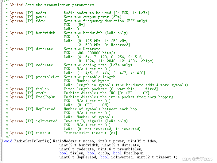
sx1268给出的驱动包可以直接调用,配置Lora的主要参数有:工作模式,发射功率,带宽、扩频因子,编码率,前导码长度等
1、发射参数配置
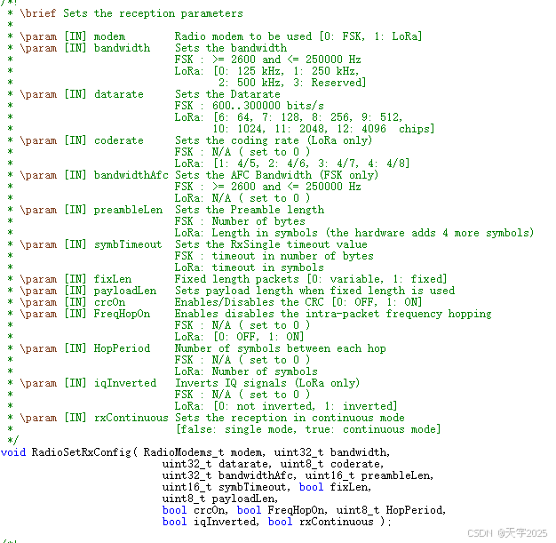
2、接收参数配置
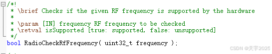
3、频率配置
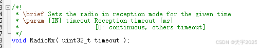
四、sx1268芯片收发控制
驱动包里的函数比较全面,可拿来直接使用
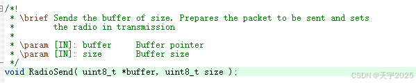
1、数据发送
2、数据接收


 1万+
1万+

 被折叠的 条评论
为什么被折叠?
被折叠的 条评论
为什么被折叠?
 到【灌水乐园】发言


