


一、三层路由器部署DHCP服务器
网络拓扑图如下
目的实现全网互通,IP由三层路由器分配,PC自动获取IP地址
适合几百人的局域网内,用路由器做DHCP服务器
1)配置trunk
某个端口要想所有vlan端口的数据通过,必须将该端口设置成中继端口(配置trunk)
根据图中所示配置中继端口。
给连接路由器f0/5端口的交换机配置trunk,允许任何vlan的数据通过
sw2>en
sw2#conf t
sw2(config)#int f0/5
sw2(config-if)#switchport mode trunk
sw1 F0/3配置trunk
sw1>en
sw1#conf t
Enter configuration commands, one per line.  End with CNTL/Z.
sw1(config)#int f0/3
sw1(config-if)#switchport mode trunk

sw1(config-if)#
%LINEPROTO-5-UPDOWN: Line protocol on Interface FastEthernet0/3, changed state to down

%LINEPROTO-5-UPDOWN: Line protocol on Interface FastEthernet0/3, changed state to up
sw2 F0/3 F0/4配置trunk
sw2>en
sw2#conf t
Enter configuration commands, one per line.  End with CNTL/Z.
sw2(config)#int f0/3
sw2(config-if)#switchport mode trunk
sw2(config-if)#exit
sw2(config)#
sw2(config)#int f0/4
sw2(config-if)#switchport mode trunk

sw2(config-if)#
%LINEPROTO-5-UPDOWN: Line protocol on Interface FastEthernet0/4, changed state to down

%LINEPROTO-5-UPDOWN: Line protocol on Interface FastEthernet0/4, changed state to up

sw2(config-if)#exit
sw3 F0/4配置trunk
sw3>en
sw3#conf t
sw3configuration commands, one per line.  End with CNTL/Z.
sw3(config)#int f0/4
sw3(config-if)#switchport mode trunk
sw3(config-if)#exit
sw3(config)#
2)VLAN创建
vlan划分,并创建vlan10/20/30/40,根据下图创建,每台交换机都要配置

这里以sw1为例,其它两台交换机同理
sw1>en
sw1#conf t
Enter configuration commands, one per line.  End with CNTL/Z.
sw1(config)#vlan 10
sw1(config-vlan)#exit
sw1(config)#vlan 20
sw1(config-vlan)#exit
sw1(config)#vlan 30
sw1(config-vlan)#exit
sw1(config)#vlan 40
sw1(config-vlan)#exit
sw1(config)#do show vlan

VLAN Name                             Status    Ports
---- -------------------------------- --------- -------------------------------
1    default                          active    Fa0/1, Fa0/2, Fa0/3, Fa0/4
                                                Fa0/5, Fa0/6, Fa0/7, Fa0/8
                                                Fa0/9, Fa0/10, Fa0/11, Fa0/12
                                                Fa0/13, Fa0/14, Fa0/15, Fa0/16
                                                Fa0/17, Fa0/18, Fa0/19, Fa0/20
                                                Fa0/21, Fa0/22, Fa0/23, Fa0/24
                                                Gig0/1, Gig0/2
10   VLAN0010                         active
20   VLAN0020                         active
30   VLAN0030                         active
40   VLAN0040                         active
1002 fddi-default                     active
1003 token-ring-default               active
1004 fddinet-default                  active
1005 trnet-default                    active

VLAN Type  SAID       MTU   Parent RingNo BridgeNo Stp  BrdgMode Trans1 Trans2
---- ----- ---------- ----- ------ ------ -------- ---- -------- ------ ------
1    enet  100001     1500  -      -      -        -    -        0      0
10   enet  100010     1500  -      -      -        -    -        0      0
20   enet  100020     1500  -      -      -        -    -        0      0
30   enet  100030     1500  -      -      -        -    -        0      0
40   enet  100040     1500  -      -      -        -    -        0      0
1002 fddi  101002     1500  -      -      -        -    -        0      0
1003 tr    101003     1500  -      -      -        -    -        0      0
1004 fdnet 101004     1500  -      -      -        ieee -        0      0
1005 trnet 101005     1500  -      -      -        ibm  -        0      0

Remote SPAN VLANs
------------------------------------------------------------------------------

Primary Secondary Type              Ports
------- --------- ----------------- ------------------------------------------
3)将端口加入对应vlan
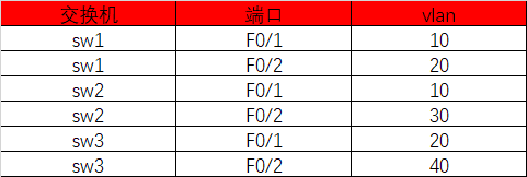
sw1配置
sw1>en
sw1#conf t
Enter configuration commands, one per line.  End with CNTL/Z.
sw1(config)#int f0/1
sw1(config-if)#switchport access vlan 10
sw1(config-if)#exit

sw1(config)#int f0/2
sw1(config-if)#switchport access vlan 20
sw1(config-if)#exit
sw1(config)#
sw2配置
sw2>en
sw2#conf t
Enter configuration commands, one per line.  End with CNTL/Z.
sw2(config)#int f0/1
sw2(config-if)#switchport access vlan 10
sw2(config-if)#exit

sw2(config)#int f0/2
sw2(config-if)#switchport access vlan 30
sw2(config-if)#exit
sw2(config)#
sw3配置
sw3>en
sw3#conf t
Enter configuration commands, one per line.  End with CNTL/Z.
sw3(config)#int f0/1
sw3(config-if)#switchport access vlan 20
sw3(config-if)#exit

sw3(config)#int f0/2
sw3(config-if)#switchport access vlan 40
sw3(config-if)#exit
sw3(config)#
配置完查看下vlan列表

4)路由创建子接口
创建子接口,不同vlan配置不同网关
Router(config)#ho r1
r1(config)#
r1(config)#
r1(config)#int f0/0.1
r1(config-subif)#
%LINK-5-CHANGED: Interface FastEthernet0/0.1, changed state to up

%LINEPROTO-5-UPDOWN: Line protocol on Interface FastEthernet0/0.1, changed state to up

r1(config-subif)#encapsulation dot1Q 10           只解析vlan10的数据
r1(config-subif)#ip add 10.1.1.254 255.255.255.0
r1(config-subif)#no shut
r1(config-subif)#exit
r1(config)#
r1(config)#int f0/0.2
r1(config-subif)#
%LINK-5-CHANGED: Interface FastEthernet0/0.2, changed state to up

%LINEPROTO-5-UPDOWN: Line protocol on Interface FastEthernet0/0.2, changed state to up
en
r1(config-subif)#encapsulation dot1Q 20        只解析vlan20的数据
r1(config-subif)#ip add 20.1.1.254 255.255.255.0
r1(config-subif)#no shut
r1(config-subif)#exit
r1(config)#

r1(config)#int f0/0.3
r1(config-subif)#
%LINK-5-CHANGED: Interface FastEthernet0/0.3, changed state to up

%LINEPROTO-5-UPDOWN: Line protocol on Interface FastEthernet0/0.3, changed state to up
en
r1(config-subif)#encapsulation dot1Q 30        只解析vlan30的数据
r1(config-subif)#ip add 30.1.1.254 255.255.255.0
r1(config-subif)#no shut
r1(config-subif)#exit
r1(config)#

r1(config)#int f0/0.4
r1(config-subif)#
%LINK-5-CHANGED: Interface FastEthernet0/0.4, changed state to up

%LINEPROTO-5-UPDOWN: Line protocol on Interface FastEthernet0/0.4, changed state to up
en
r1(config-subif)#encapsulation dot1Q 40        只解析vlan40的数据
r1(config-subif)#ip add 40.1.1.254 255.255.255.0
r1(config-subif)#no shut
r1(config-subif)#exit

r1(config)#int f0/0
r1(config-if)#no shut   开启父级接口
查看路由表
r1(config)#do show ip route
Codes: C - connected, S - static, I - IGRP, R - RIP, M - mobile, B - BGP
       D - EIGRP, EX - EIGRP external, O - OSPF, IA - OSPF inter area
       N1 - OSPF NSSA external type 1, N2 - OSPF NSSA external type 2
       E1 - OSPF external type 1, E2 - OSPF external type 2, E - EGP
       i - IS-IS, L1 - IS-IS level-1, L2 - IS-IS level-2, ia - IS-IS inter area
       * - candidate default, U - per-user static route, o - ODR
       P - periodic downloaded static route

Gateway of last resort is not set

     10.0.0.0/24 is subnetted, 1 subnets
C       10.1.1.0 is directly connected, FastEthernet0/0.1
     20.0.0.0/24 is subnetted, 1 subnets
C       20.1.1.0 is directly connected, FastEthernet0/0.2
     30.0.0.0/24 is subnetted, 1 subnets
C       30.1.1.0 is directly connected, FastEthernet0/0.3
     40.0.0.0/24 is subnetted, 1 subnets
C       40.1.1.0 is directly connected, FastEthernet0/0.4
5)路由器创建地址池
创建地址池
ip dhcp excluded-address 10.1.1.1 10.1.1.99    排除ip
ip dhcp pool v10                               地址池命名
network 10.1.1.0 255.255.255.0                 要提供的网段地址和子网掩码
default-router 10.1.1.254                      指定网关
dns-server 40.1.1.1                            dns
exit
ip dhcp excluded-address 20.1.1.1 20.1.1.99
ip dhcp pool v20
network 20.1.1.0 255.255.255.0
default-router 20.1.1.254
dns-server 40.1.1.1
exit
ip dhcp excluded-address 30.1.1.1 30.1.1.99
ip dhcp pool v30
network 30.1.1.0 255.255.255.0
default-router 30.1.1.254
dns-server 40.1.1.1
exit
删除地址池
conf t
no ip dhcp excluded-address 10.1.1.1 10.1.1.99
no ip dhcp pool v10
查看配置:do show run
自动获取IP


PC0分别PING 20/30网段的主机

6)服务器配置静态IP

PC0 ping dns服务器
C:\>ping 40.1.1.1

Pinging 40.1.1.1 with 32 bytes of data:

Request timed out.
Reply from 40.1.1.1: bytes=32 time=1ms TTL=127
Reply from 40.1.1.1: bytes=32 time<1ms TTL=127
Reply from 40.1.1.1: bytes=32 time<1ms TTL=127

Ping statistics for 40.1.1.1:
    Packets: Sent = 4, Received = 3, Lost = 1 (25% loss),
Approximate round trip times in milli-seconds:
    Minimum = 0ms, Maximum = 1ms, Average = 0ms

C:\>

二、DHCP服务器部署
继续上面的操作,上面是将路由器做DHCP服务器,下面我们要使用dns服务器做服务器,当公司人数超过千人时路由器不适合做DHCP。
进入路由删除上面配置的地址池
conf t
no ip dhcp excluded-address 10.1.1.1 10.1.1.99
no ip dhcp pool v10
no ip dhcp excluded-address 20.1.1.1 20.1.1.99
no ip dhcp pool v20
no ip dhcp excluded-address 30.1.1.1 30.1.1.99
no ip dhcp pool v30
1)创建作用域

2)在三层设备配置DHCP中继
作用:跨网段获取IP地址
哪些vlan需要路由转发DHCP广播,就在路由对应的接口配置DHCP中继
r1>en
r1#conf t
Enter configuration commands, one per line.  End with CNTL/Z.
r1(config)#int f0/0.1
r1(config-subif)#ip helper-address 40.1.1.1
r1(config-subif)#exit

r1(config)#int f0/0.2
r1(config-subif)#ip helper-address 40.1.1.1
r1(config-subif)#exit

r1(config)#int f0/0.3
r1(config-subif)#ip helper-address 40.1.1.1
r1(config-subif)#exit
r1(config)#

DHCP中继原理
PC1发送一个DHCP广播包,经过交换机的vlan10,最后转发到路由器的f0/0.1接口,f0/0.1只能解析来自vlan10的数据包,并且这个广播包到f0/0.1后不会在转发出去,因为做了vlan限制了广播域,其他接口均收不到,因此为了让这个数据包转发给DHCP服务器,我们需要在f0/0.1这个接口开启DHCP中继,让这个广播包到达f0/0.1这个接口后在单独发送给DHCP服务器一份。


 1741
1741


 被折叠的 条评论
为什么被折叠?
被折叠的 条评论
为什么被折叠?
 到【灌水乐园】发言


