


一、链路聚合技术
随着我们网络的不断拓展,业务流量也随之增多,那么我们就开始需要多链路进行通信
故研究出一个技术==Eth-Trunk(链路捆绑)
作用:
可以把多个独立的物理端口绑定在一起,当做一个大带宽逻辑接口去使用,这样的方法既不用替换端口也不必浪费IP地址资源
组建网络遇到的问题:
1. 网络需求大,单链路无法完成,增加链路又浪费IP地址,更换高带宽接口(E口换G口)又会增加维护设备的成本
2. 如果链路发生故障,又会影响通信和办公
解决:
两个问题均可以用eth-trunk来解决,将多个e口绑定为一起带宽转发就会增加(不必使用G口)由于是多个端口绑定故即便发生端口故障或者是单条链路故障也没有关系,因为其他端口也会进行转发(如果物理端口断掉,带宽转发也会稍微影响:比如,我用四条链路组成了一个链路捆绑(4000M)那么断开一个的话(-1000M),转发就会变成3000M)
Eth-Trunk链路聚合模式:
静态配置模式(手工负载分担)
动态配置模式(LACP)
Eth-trunk接口负载分担:
可以选择IP地址或者包作为负载分担依据
设置成员接口的负载分担分配
如果一个成员的分配权重值越大,承担的负载就越大
逐流负载分担:
当源地址、目标地址都相同或者报文的源MAC地址、目标MAC地址都相同时,就会在一条链路上传输
逐包负载分担:
以报文为单位分别从不同的成员链路上发送
手工负载分担模式:
当两台设备其中一个不支持LACP时,可以用手工负载方式来增加设备间的带宽和可靠性
Eth-Trunk接口配置流程:
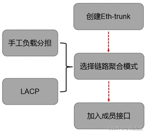
Eth-Trunk接口配置流程:
[Huawei]interface eth-trunk 1
[Huawei-Eth-trunk1]mode manual load-balan//设置为手工负载分担
[Huawei-Eth-trunk1]trunkport g 0/0/X//加入端口
[Huawei-Eth-trunk1]port link-t access/trunk//设置端口模式,这里根据拓扑要求来设置即可
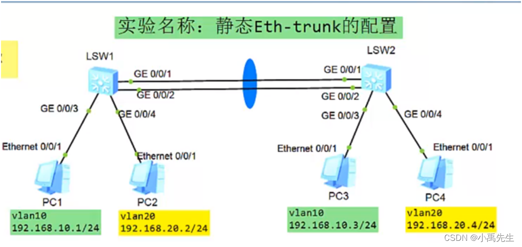
实验一 配置手工负载分担模式

S1交换机的初始配置
<Huawei>u t m
<Huawei>system-view
[S1]sysname S1
创建vlan并将接口加入vlan设置接口的模式为acess:
[S1]vlan batch 10 20 \\创建vlan 10 20
[S1]interface g0/0/1\\进入接口0/0/1
[S1-GigabitEthernet0/0/1]port link-type access \\设置接口模式为接入链路
[S1-GigabitEthernet0/0/1]port default vlan 10 \\将接口加入vlan10
[S1]interface g0/0/2\\进入接口0/0/2
[S1-GigabitEthernet0/0/2]port link-type access\\设置接口模式为接入链路
[S1-GigabitEthernet0/0/2]port default vlan 20 \\将接口加入vlan20
配置链路聚合:手工负载分担模式
[S1] interface(接口) eth-trunk(以太 - 中继)1 \\创建链路聚合的端口1(0-63)
[S1-Eth-Trunk1]mode(模式) manual(手控制的) load(负载)-balance(均衡)
[S1-Eth-Trunk1]trunkport(中继端口) g0/0/3 \\将接口加入到负载模式
[S1-Eth-Trunk1]trunkport(中继端口) g0/0/4 \\将接口加入到负载模式
[S1-Eth-Trunk1]display eth-trunk 1 \\查看 eth-trunk
[S1]int eth-trunk 1 \\进入eth-trunk1
[S1-Eth-Trunk1]port link-type trunk \\设置为trunk链路
[S1-Eth-Trunk1]port trunk allow-pass vlan all \\ 设置为允许所有vlan
S2交换机的初始配置
<Huawei>u t m
<Huawei>system-view
[Huawei]sysname S2
创建vlan并将接口加入vlan:
[S2]vlan batch 10 20 \\创建vlan 10 20
[S2]interface g0/0/1\\进入接口0/0/5
[S2-GigabitEthernet0/0/1]port link-type access \\设置接口模式为接入链路
[S2-GigabitEthernet0/0/1]port default vlan 10 \\将接口加入vlan10
[S2]interface g0/0/2\\进入接口0/0/5
[S2-GigabitEthernet0/0/2]port link-type access\\设置接口模式为接入链路
[S2-GigabitEthernet0/0/2]port default vlan 20 \\将接口加入vlan20
配置链路聚合:手工负载分担模式
[S2] interface(接口) eth-trunk(以太 - 中继)1 \\创建链路聚合的端口1(0-63)
[S2-Eth-Trunk1]mode(模式) manual(手控制的) load(负载)-balance(均衡)
[S2-Eth-Trunk1]trunkport(中继端口) g0/0/3 \\将接口加入到负载模式
[S2-Eth-Trunk1]trunkport(中继端口) g0/0/4 \\将接口加入到负载模式
[S2-Eth-Trunk1]display eth-trunk 1 \\查看 eth-trunk
[S2]int eth-trunk 1 \\进入eth-trunk1
[S2-Eth-Trunk1]port link-type trunk \\设置为trunk链路
[S2-Eth-Trunk1]port trunk allow-pass vlan all \\ 设置为允许所有vlan
[S2-Eth-Trunk1]display eth-trunk 1 \\查看 eth-trunk
[S2]display port vlan \\查看 vlan
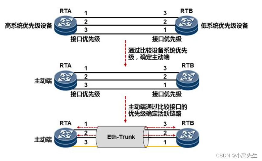
二、LACP模式
也可以称之为M:N模式
M代表处于活动状态的转发数据
N代表处于非活动状态的备份链路
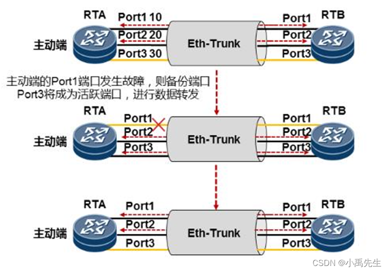
比如我们建立的三条链路,就是两条转发,1条备份,当转发链路出现故障的时候,备份链路才会进行数据转发,平时是不转发数据的
LACP的选取:
LACP的抢占:
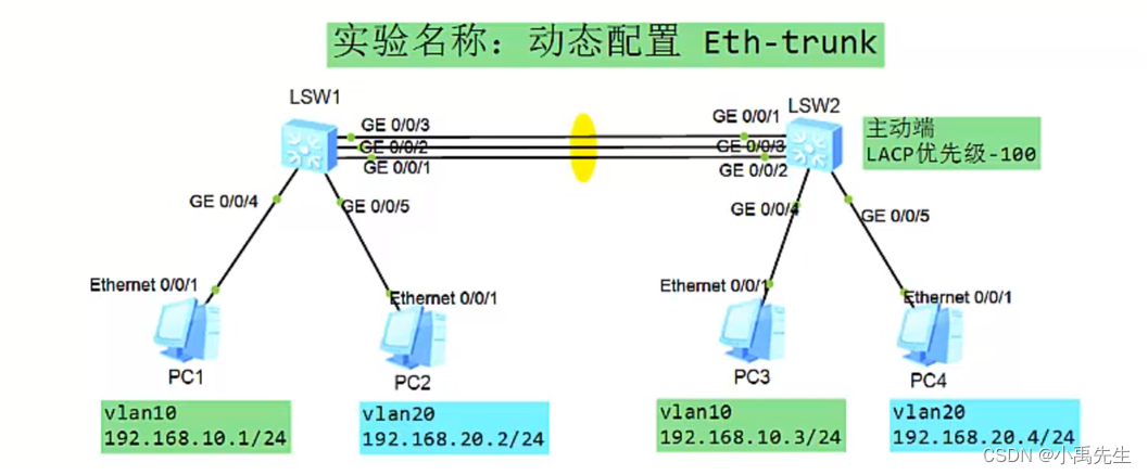
实验二 配置LACP负载分担模式
S1交换机的初始配置
<Huawei>u t m
<Huawei>system-view
[S1]sysname S1
创建vlan并将接口加入vlan设置接口的模式为acess:
[S1]vlan batch 10 20 \\创建vlan 10 20
[S1]interface g0/0/4 \\进入接口0/0/4
[S1-GigabitEthernet0/0/4]port link-type access \\设置接口模式为接入链路
[S1-GigabitEthernet0/0/4]port default vlan 10 \\将接口加入vlan10
[S1]interface gth0/0/5 \\进入接口0/0/5
[S1-GigabitEthernet0/0/5]port link-type access\\设置接口模式为接入链路
[S1-GigabitEthernet0/0/5]port default vlan 20 \\将接口加入vlan20
配置链路聚合:LACP模式
[S1] interface(接口) eth-trunk(以太 - 中继)1 \\创建链路聚合的端口1(0-63)
[S1-Eth-Trunk1]mode(模式) lacp(动态)-static(均衡)
[S1-Eth-Trunk1]trunkport(中继端口) g0/0/1 \\将接口加入到负载模式
[S1-Eth-Trunk1]trunkport(中继端口) g0/0/2 \\将接口加入到负载模式
[S1-Eth-Trunk1]trunkport(中继端口) g0/0/3 \\将接口加入到负载模式
[S1-Eth-Trunk1]port link-type trunk \\设置为trunk链路
[S1-Eth-Trunk1]port trunk allow-pass vlan all \\ 设置为允许所有vlan
[S1-Eth-Trunk1]display eth-trunk 1 \\查看 eth-trunk
[S1]int eth-trunk 1 \\进入eth-trunk1
S2交换机的初始配置
<Huawei>u t m
<Huawei>system-view
[Huawei]sysname S2
创建vlan并将接口加入vlan:
[S2]vlan batch 10 20 \\创建vlan 10 20
[S2]interface g0/0/4 \\进入接口0/0/5
[S2-GigabitEthernet0/0/4]port link-type access \\设置接口模式为接入链路
[S2-GigabitEthernet0/0/4]port default vlan 10 \\将接口加入vlan10
[S2]interface g0/0/5 \\进入接口0/0/5
[S2-GigabitEthernet0/0/5]port link-type access\\设置接口模式为接入链路
[S2-GigabitEthernet0/0/5]port default vlan 20 \\将接口加入vlan20
配置链路聚合:LACP模式
[S2] interface(接口) eth-trunk(以太 - 中继)1 \\创建链路聚合的端口1(0-63)
[S2-Eth-Trunk1] mode(模式) lacp(动态)-static(均衡)
[S2-Eth-Trunk1]trunkport(中继端口)g0/0/1 \\将接口加入到负载模式
[S2-Eth-Trunk1]trunkport(中继端口) g0/0/2 \\将接口加入到负载模式
[S2-Eth-Trunk1]trunkport(中继端口) g0/0/3 \\将接口加入到负载模式
[S2-Eth-Trunk1]port link-type trunk \\设置为trunk链路
[S2-Eth-Trunk1]port trunk allow-pass vlpe trunkan all \\ 设置为允许所有vlan
[S2-Eth-Trunk1]display eth-trunk 1 \\查看 eth-trunk
[S2]display port vlan \\查看 vlan
[S2]display eth-trunk 1 \\查看 eth-trunk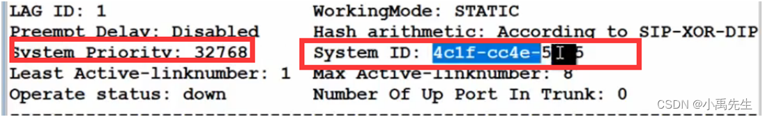
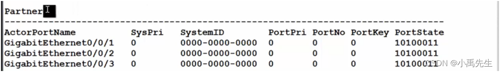
Local:本地信息 Partner:对端信息
Svstem Prioritv:32768 系统的优先级
System ID:4clf-cc4e-5 系统的mac地址
MAX Active-linknumber:8 最大的活动链路数是8条
链路数是可以进行调整的我们可以调整为2条
Number of Up Port In Trunk:0 目前有几条
端口的编号端口的状态端口的带宽 接口的优先级 接口编号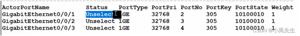
UNSELECT 为备份端口 Selected 为活动端口
我们使用的是千兆端口,目前对方的信息都是0还没有启动
S2设置他的链路为2:
[S2]display eth-trunk 1 \\查看 eth-trunk
[S2]int eth-trunk 1 \\进入eth-trunk1
[S2-Eth-Trunk1]max active-linknumber 2\\设置为2条链路
修改sw2为主设备,默认值是32768 我们可以设置为100
[S2]lacp priority 100 \\设置默认值为100
[S2]display eth-trunk 1 \\查看 eth-trunk
设置S2抢占功能:
- 模拟1接口出现故障了
[S2]int g0/0/1 \\加入接口1
[S2-GigabitEthernet0/0/1]shutdows \\关闭接口
[S2]display eth-trunk 1 \\查看 eth-trunk
[S2]display eth-trunk \\查看 eth-trunk
Preempt Delay:Disabled 当前抢占功能未开启
- 配置启用抢占模式 S1 S2都需要开启
[S2]display eth-trunk 2 \\查看 eth-trunk
[S2-Eth-Trunk1]lacp preempt enable \\配置抢占模式
[S1]display eth-trunk 1 \\查看 eth-trunk
[S1-Eth-Trunk1]lacp preempt enable \\配置抢占模式
[S2]display eth-trunk \\查看 eth-trunk
Preempt Delay Time:30 当前抢占功能已开启 30秒后抢
综合实验
三、链路聚合综合实战:
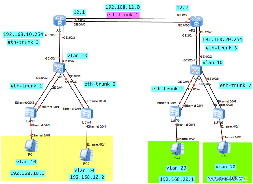
一、二层交换机的配置 S1 S2 S3 S4 S5 S6
1.S1交换机的初始配置
<Huawei>u t m \\关闭信息干扰
<Huawei>system-view \\进入系统视图
[Huawei]sysname S1 \\设置交换机的名字为S1
- S1创建vlan 10 20
[S1]vlan batch 10 20 \\创建vlan 10 20
3.创建链路聚合接口eth-trunk 1 、2并将设置模式为lacp、加入成员并设置链路为tunk并允许所有vlan通过
[S1]interface Eth-Trunk 1 \\创建链路聚合的端口1
[S1-Eth-Trunk1]mode lacp-static \\设置链路为动态lacp
[S1-Eth-Trunk1]trunkport e0/0/3 \\将接口加入到负载模式
[S1-Eth-Trunk1]trunkport e0/0/4 \\将接口加入到负载模式
[S1-Eth-Trunk1]port link-type trunk \\设置为trunk链路
[S1-Eth-Trunk1] port trunk allow-pass vlan all \\并允许所有vlan通过
[S1-Eth-Trunk1]display eth-trunk 1 \\查看 eth-trunk
[S1]interface Eth-Trunk2\\创建链路聚合的端口2
[S1-Eth-Trunk2]mode lacp-static \\设置链路为动态lacp
[S1-Eth-Trunk2]trunkport e0/0/5\\将接口加入到负载模式
[S1-Eth-Trunk2]trunkport e0/0/6 \\将接口加入到负载模式
[S1-Eth-Trunk2]port link-type trunk \\设置为trunk链路
[S1-Eth-Trunk2] port trunk allow-pass vlan all \\并允许所有vlan通过
[S1-Eth-Trunk2]display eth-trunk 2 \\查看 eth-trunk
4.创建链路聚合接口eth-trunk 3 并将设置模式为lacp、加入成员并设置链路为access并将此端口加入vlan10
[S1]interface Eth-Trunk3\\创建链路聚合的端口3
[S1-Eth-Trunk3]mode lacp-static \\设置链路为动态lacp
[S1-Eth-Trunk3]trunkport e0/0/1\\将接口加入到负载模式
[S1-Eth-Trunk3]trunkport e0/0/2 \\将接口加入到负载模式
[S1-Eth-Trunk3]port link-type access\\设置为access链路
[S1-Eth-Trunk3] port default vlan 10\\并将此端口加入vlan10
1.S2交换机的初始配置
<Huawei>u t m \\关闭信息干扰
<Huawei>system-view \\进入系统视图
[Huawei]sysname S2 \\设置交换机的名字为S2
- S2创建vlan 10 20
[S2]vlan batch 10 20 \\创建vlan 10 20
3.创建链路聚合接口eth-trunk 1 、2并将设置模式为lacp、加入成员并设置链路为tunk并允许所有vlan通过
[S2]interface Eth-Trunk 1 \\创建链路聚合的端口1
[S2-Eth-Trunk1]mode lacp-static \\设置链路为动态lacp
[S2-Eth-Trunk1]trunkport e0/0/3 \\将接口加入到负载模式
[S2-Eth-Trunk1]trunkport e0/0/4 \\将接口加入到负载模式
[S2-Eth-Trunk1]port link-type trunk \\设置为trunk链路
[S2-Eth-Trunk1] port trunk allow-pass vlan all \\并允许所有vlan通过
[S2-Eth-Trunk1]display eth-trunk 1 \\查看 eth-trunk
[S2]interface Eth-Trunk2\\创建链路聚合的端口2
[S2-Eth-Trunk2]mode lacp-static \\设置链路为动态lacp
[S2-Eth-Trunk2]trunkport e0/0/5\\将接口加入到负载模式
[S2-Eth-Trunk2]trunkport e0/0/6 \\将接口加入到负载模式
[S2-Eth-Trunk2]port link-type trunk \\设置为trunk链路
[S2-Eth-Trunk2] port trunk allow-pass vlan all \\并允许所有vlan通过
[S2-Eth-Trunk2]display eth-trunk 2 \\查看 eth-trunk
4.创建链路聚合接口eth-trunk 3 并将设置模式为lacp、加入成员并设置链路为access并将此端口加入vlan10
[S2]interface Eth-Trunk3\\创建链路聚合的端口3
[S2-Eth-Trunk3]mode lacp-static \\设置链路为动态lacp
[S2-Eth-Trunk3]trunkport e0/0/1\\将接口加入到负载模式
[S2-Eth-Trunk3]trunkport e0/0/2 \\将接口加入到负载模式
[S2-Eth-Trunk3]port link-type access\\设置为access链路
[S2-Eth-Trunk3] port default vlan 20\\并将此端口加入vlan20
1.S3交换机的初始配置
<Huawei>u t m \\关闭信息干扰
<Huawei>system-view \\进入系统视图
[Huawei]sysname S3 \\设置交换机的名字为S3
- S3创建vlan 10 20
[S3]vlan batch 10 20 \\创建vlan 10 20
3.创建链路聚合接口eth-trunk 1并将设置模式为lacp、加入成员并设置链路为tunk并允许所有vlan通过
[S3]interface Eth-Trunk 1 \\创建链路聚合的端口1
[S3-Eth-Trunk1]mode lacp-static \\设置链路为动态lacp
[S3-Eth-Trunk1]trunkport e0/0/3 \\将接口加入到负载模式
[S3-Eth-Trunk1]trunkport e0/0/4 \\将接口加入到负载模式
[S3-Eth-Trunk1]port link-type trunk \\设置为trunk链路
[S3-Eth-Trunk1] port trunk allow-pass vlan all \\并允许所有vlan通过
[S3-Eth-Trunk1]display eth-trunk 1 \\查看 eth-trunk
4.S3将e0/0/1加入vlan10 并设置链路是access链路
[S3]int e0/0/1 \\进入接口0/0/1
[S3-Ethernet0/0/1]port link-type access \\设置链路为接入链路(access链路)
[S3-Ethernet0/0/1]port default vlan 10 \\将接口加入vlan10
1.S4交换机的初始配置
<Huawei>u t m \\关闭信息干扰
<Huawei>system-view \\进入系统视图
[Huawei]sysname S4 \\设置交换机的名字为S4
- S4创建vlan 10 20
[S4]vlan batch 10 20 \\创建vlan 10 20
3.S4创建链路聚合接口eth-trunk 2 并将设置模式为lacp、加入成员并设置链路为tunk并允许所有vlan通过
[S4]interface Eth-Trunk 2\\创建链路聚合的端口2
[S4-Eth-Trunk2]mode lacp-static \\设置链路为动态lacp
[S4-Eth-Trunk2]trunkport e0/0/5\\将接口加入到负载模式
[S4-Eth-Trunk2]trunkport e0/0/6 \\将接口加入到负载模式
[S4-Eth-Trunk2]port link-type trunk \\设置为trunk链路
[S4-Eth-Trunk2] port trunk allow-pass vlan all \\并允许所有vlan通过
[S4-Eth-Trunk2]display eth-trunk 2 \\查看 eth-trunk
4.S4将e0/0/1加入vlan10 并设置链路是access链路
[S4]int e0/0/1 \\进入接口0/0/1
[S4-Ethernet0/0/1]port link-type access \\设置链路为接入链路(access链路)
[S4-Ethernet0/0/1]port default vlan 10 \\将接口加入vlan10
1.S5交换机的初始配置
<Huawei>u t m \\关闭信息干扰
<Huawei>system-view \\进入系统视图
[Huawei]sysname S5\\设置交换机的名字为S5
- S5创建vlan 10 20
[S5]vlan batch 10 20 \\创建vlan 10 20
3.创建链路聚合接口eth-trunk 1并将设置模式为lacp、加入成员并设置链路为tunk并允许所有vlan通过
[S5]interface Eth-Trunk 1 \\创建链路聚合的端口1
[S5-Eth-Trunk1]mode lacp-static \\设置链路为动态lacp
[S5-Eth-Trunk1]trunkport e0/0/3 \\将接口加入到负载模式
[S5-Eth-Trunk1]trunkport e0/0/4 \\将接口加入到负载模式
[S5-Eth-Trunk1]port link-type trunk \\设置为trunk链路
[S5-Eth-Trunk1] port trunk allow-pass vlan all \\并允许所有vlan通过
[S5-Eth-Trunk1]display eth-trunk 1 \\查看 eth-trunk
4.S5将e0/0/1加入vlan20 并设置链路是access链路
[S5]int e0/0/1 \\进入接口0/0/1
[S5-Ethernet0/0/1]port link-type access \\设置链路为接入链路(access链路)
[S5-Ethernet0/0/1]port default vlan 20 \\将接口加入vlan10
1.S6交换机的初始配置
<Huawei>u t m \\关闭信息干扰
<Huawei>system-view \\进入系统视图
[Huawei]sysname S6 \\设置交换机的名字为S6
- S6创建vlan 10 20
[S6]vlan batch 10 20 \\创建vlan 10 20
3.S6创建链路聚合接口eth-trunk 2 并将设置模式为lacp、加入成员并设置链路为tunk并允许所有vlan通过
[S6]interface Eth-Trunk 2\\创建链路聚合的端口2
[S6-Eth-Trunk2]mode lacp-static \\设置链路为动态lacp
[S6-Eth-Trunk2]trunkport e0/0/5\\将接口加入到负载模式
[S6-Eth-Trunk2]trunkport e0/0/6 \\将接口加入到负载模式
[S6-Eth-Trunk2]port link-type trunk \\设置为trunk链路
[S6-Eth-Trunk2] port trunk allow-pass vlan all \\并允许所有vlan通过
[S6-Eth-Trunk2]display eth-trunk 2 \\查看 eth-trunk
4.S6将e0/0/1加入vlan20 并设置链路是access链路
[S6]int e0/0/1 \\进入接口0/0/1
[S6-Ethernet0/0/1]port link-type access \\设置链路为接入链路(access链路)
[S6-Ethernet0/0/1]port default vlan 20 \\将接口加入vlan20
三、路由器的配置R1 R2
1.R1路由器的初始配置
<Huawei>u t m
<Huawei>system-view
[Huawei]sysname R1
2.R1路由器接口2/0/1 2/0/2接口设置链路聚合3并配置IP地址
[R1]interface Eth-Trunk 3 \\创建链路聚合的端口3
[R1-Eth-Trunk3]undo portswitch \\关闭接口的交换功能(默认无法配置IP地址)
[R1-Eth-Trunk3]mode lacp-static\\设置链路为动态lacp
[R1-Eth-Trunk3]trunkport g2/0/1\\将接口加入到负载模式
[R1-Eth-Trunk3]trunkport g2/0/2\\将接口加入到负载模式
[R1-Eth-Trunk3]ip add 192.168.10.254 24\\配置IP地址
[R1-Eth-Trunk3]quit
3.R1路由器接口0/0/0 0/0/1接口设置链路聚合1并配置IP地址
[R1]interface Eth-Trunk 1
[R1-Eth-Trunk1]undo portswitch\\关闭接口的交换功能(默认无法配置IP地址)
[R1-Eth-Trunk1]mode lacp-static \\设置链路为动态lacp
[R1-Eth-Trunk1]trunkport g0/0/0\\将接口加入到负载模式
[R1-Eth-Trunk1]trunkport g0/0/1\\将接口加入到负载模式
[R1-Eth-Trunk1]ip add 192.168.12.1 24\\配置IP地址
1.R2路由器的初始配置
<Huawei>u t m
<Huawei>system-view
[Huawei]sysname R2
2.R2路由器接口2/0/1 2/0/2接口设置链路聚合3并配置IP地址
[R2]interface Eth-Trunk 3 \\创建链路聚合的端口3
[R2-Eth-Trunk3]undo portswitch \\关闭接口的交换功能(默认无法配置IP地址)
[R2-Eth-Trunk3]mode lacp-static\\设置链路为动态lacp
[R2-Eth-Trunk3]trunkport g2/0/1\\将接口加入到负载模式
[R2-Eth-Trunk3]trunkport g2/0/2\\将接口加入到负载模式
[R2-Eth-Trunk3]ip add 192.168.20.254 24\\配置IP地址
[R2-Eth-Trunk3]quit
3.R1路由器接口0/0/0 0/0/1接口设置链路聚合1并配置IP地址
[R2]interface Eth-Trunk 1
[R2-Eth-Trunk1]undo portswitch\\关闭接口的交换功能(默认无法配置IP地址)
[R2-Eth-Trunk1]mode lacp-static \\设置链路为动态lacp
[R2-Eth-Trunk1]trunkport g0/0/0\\将接口加入到负载模式
[R2-Eth-Trunk1]trunkport g0/0/1\\将接口加入到负载模式
[R2-Eth-Trunk1]ip add 192.168.12.2 24\\配置IP地址
四、路由器的静态配置
1.R1路由器的静态路由配置
[R1]ip route-static 192.168.20.0 24 192.168.12.2
4.R2路由器的静态路由配置
[R2]ip route-static 192.168.10.0 24 192.168.12.1
- 测试连通性
PC1: ping 192.168.20.1
PC1: ping 192.168.20.2


 1万+
1万+

 被折叠的 条评论
为什么被折叠?
被折叠的 条评论
为什么被折叠?
 到【灌水乐园】发言


