


这里写目录标题
常用传感器讲解一–遥控杆-KY-023(joystick)
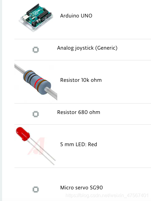
主要电子材料
具体讲解
Arduino Uno操纵杆控制器主要用于机器人手臂,记录坐标。允许重复记录坐标一次单击按钮或重复。使用Arduino Uno基板,不用附加板。需要USB连接(2A)或6V / 2A电源。使用四个伺服SG90进行测试。
按下操纵杆k1上的按钮开始记录坐标。按下操纵杆1上的按钮结束坐标记录。
按下操纵杆2上的按钮,开始重播录制的坐标。按下操纵杆2上的按钮停止重播录制的坐标。按住操纵杆2上的按钮,开始循环自动回放所记录的坐标。
硬件连线
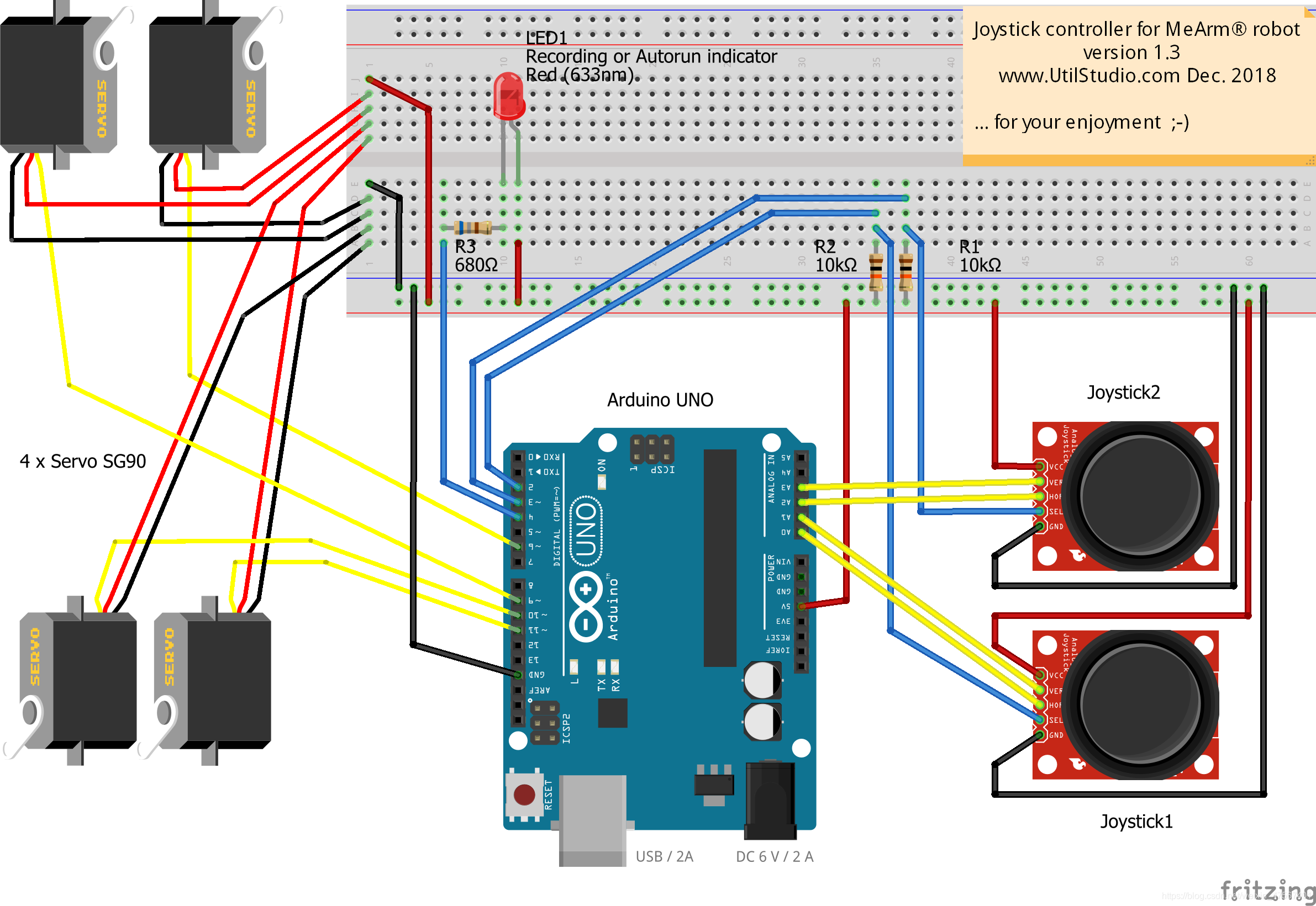
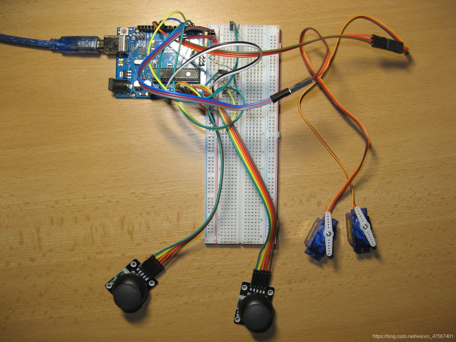
这里只有两个伺服连接的测试板。连接4台伺服电机见原理图。
代码展示
/* meArm analog joysticks version 1.3.1 - UtilStudio.com Dec 2018
   Uses two analogue joysticks and four servos.

   In version 1.3 was improved recording of coordinates.
   Some bugs was removed.

   First joystick moves gripper forwards, backwards, left and right,
   button start/stop recording positions.

   Second joystick moves gripper up, down, and closes and opens,
   button start/stop playing recorded positions.
   Press button for 2 seconds to autoplay.

   Pins:
   Arduino    Stick1    Stick2    Base   Shoulder  Elbow    Gripper   Record/
      GND       GND       GND    Brown     Brown   Brown     Brown    Auto play
       5V       VCC       VCC      Red       Red     Red       Red    LED
       A0       HOR
       A1       VER
       PD2      BUTT
       A2                 HOR
       A3                 VER
       PD3                BUTT
       11                       Yellow
       10                                 Yellow
        9                                         Yellow
        6                                                   Yellow
       PD4                                                            X
*/
#include <Servo.h>

bool repeatePlaying = false; /* Repeatedly is running recorded cycle */
int delayBetweenCycles = 2000; /* Delay between cycles */

int basePin = 11;       /* Base servo */
int shoulderPin = 10;   /* Shoulder servo */
int elbowPin = 9;       /* Elbow servo */
int gripperPin = 6;     /* Gripper servo */

int xdirPin = 0;        /* Base - joystick1*/
int ydirPin = 1;        /* Shoulder - joystick1 */
int zdirPin = 3;        /* Elbow - joystick2 */
int gdirPin = 2;        /* Gripper - joystick2 */

//int pinRecord = A4;     /* Button record - backward compatibility */
//int pinPlay = A5;       /* Button play  - backward compatibility */
int pinRecord = PD2;     /* Button record - recommended (A4 is deprecated, will by used for additional joystick) */
int pinPlay = PD3;       /* Button play  - recommended (A5 is deprecated, will by used for additional joystick) */
int pinLedRecord = PD4;  /* LED - indicates recording (light) or auto play mode (blink one) */

bool useInternalPullUpResistors = false;

const int buffSize = 512; /* Size of recording buffer */

int startBase = 90;
int startShoulder = 90;
int startElbow = 90;
int startGripper = 0;

int posBase = 90;
int posShoulder = 90;
int posElbow = 90;
int posGripper = 0;

int lastBase = 90;
int lastShoulder = 90;
int lastElbow = 90;
int lastGripper = 90;

int minBase = 0;
int maxBase = 150;
int minShoulder = 0;
int maxShoulder = 150;
int minElbow = 0;
int maxElbow = 150;
int minGripper = 0;
int maxGripper = 150;

const int countServo = 4;
int buff[buffSize];
int buffAdd[countServo];
int recPos = 0;
int playPos = 0;

int buttonRecord = HIGH;
int buttonPlay = HIGH;

int buttonRecordLast = LOW;
int buttonPlayLast = LOW;

bool record = false;
bool play = false;
bool debug = false;

String command = "Manual";
int printPos = 0;

int buttonPlayDelay = 20;
int buttonPlayCount = 0;

bool ledLight = false;

Servo servoBase;
Servo servoShoulder;
Servo servoElbow;
Servo servoGripper;

void setup() {
  Serial.begin(9600);

  if (useInternalPullUpResistors) {
    pinMode(pinRecord, INPUT_PULLUP);
    pinMode(pinPlay, INPUT_PULLUP);
  }
  else
  {
    pinMode(pinRecord, INPUT);
    pinMode(pinPlay, INPUT);
  }

  pinMode(xdirPin, INPUT);
  pinMode(ydirPin, INPUT);
  pinMode(zdirPin, INPUT);
  pinMode(gdirPin, INPUT);

  pinMode(pinLedRecord, OUTPUT);

  servoBase.attach(basePin);
  servoShoulder.attach(shoulderPin);
  servoElbow.attach(elbowPin);
  servoGripper.attach(gripperPin);

  StartPosition();

  digitalWrite(pinLedRecord, HIGH);
  delay(1000);
  digitalWrite(pinLedRecord, LOW);
}

void loop() {

  buttonRecord = digitalRead(pinRecord);
  buttonPlay = digitalRead(pinPlay);

  //  Serial.print(buttonRecord);
  //  Serial.print("\t");
  //  Serial.println(buttonPlay);
  //  for testing purposes

  if (buttonPlay == LOW)
  {
    buttonPlayCount++;

    if (buttonPlayCount >= buttonPlayDelay)
    {
      repeatePlaying = true;
    }
  }
  else buttonPlayCount = 0;

  if (buttonPlay != buttonPlayLast)
  {
    if (record)
    {
      record = false;
    }

    if (buttonPlay == LOW)
    {
      play = !play;
      repeatePlaying = false;

      if (play)
      {
        StartPosition();
      }
    }
  }

  if (buttonRecord != buttonRecordLast)
  {
    if (buttonRecord == LOW)
    {
      record = !record;

      if (record)
      {
        play = false;
        repeatePlaying = false;
        recPos = 0;
      }
      else
      {
        if (debug) PrintBuffer();
      }
    }
  }

  buttonPlayLast = buttonPlay;
  buttonRecordLast = buttonRecord;

  float dx = map(analogRead(xdirPin), 0, 1023, -5.0, 5.0);
  float dy = map(analogRead(ydirPin), 0, 1023, 5.0, -5.0);
  float dz = map(analogRead(zdirPin), 0, 1023, 5.0, -5.0);
  float dg = map(analogRead(gdirPin), 0, 1023, 5.0, -5.0);

  if (abs(dx) < 1.5) dx = 0;
  if (abs(dy) < 1.5) dy = 0;
  if (abs(dz) < 1.5) dz = 0;
  if (abs(dg) < 1.5) dg = 0;

  posBase += dx;
  posShoulder += dy;
  posElbow += dz;
  posGripper += dg;

  if (play)
  {
    if (playPos >= recPos) {
      playPos = 0;

      if (repeatePlaying)
      {
        delay(delayBetweenCycles);
        StartPosition();
      }
      else
      {
        play = false;
      }
    }

    bool endOfData = false;

    while (!endOfData)
    {
      if (playPos >= buffSize - 1) break;
      if (playPos >= recPos) break;

      int data = buff[playPos];
      int angle = data & 0xFFF;
      int servoNumber = data & 0x3000;
      endOfData = data & 0x4000;

      switch (servoNumber)
      {
        case 0x0000:
          posBase = angle;
          break;

        case 0x1000:
          posShoulder = angle;
          break;

        case 0x2000:
          posElbow = angle;
          break;

        case 0x3000:
          posGripper = angle;
          dg = posGripper - lastGripper;
          break;
      }

      playPos++;
    }
  }

  if (posBase > maxBase) posBase = maxBase;
  if (posShoulder > maxShoulder) posShoulder = maxShoulder;
  if (posElbow > maxElbow) posElbow = maxElbow;
  if (posGripper > maxGripper) posGripper = maxGripper;

  if (posBase < minBase) posBase = minBase;
  if (posShoulder < minShoulder) posShoulder = minShoulder;
  if (posElbow < minElbow) posElbow = minElbow;
  if (posGripper < minGripper) posGripper = minGripper;

  servoBase.write(posBase);
  servoShoulder.write(posShoulder);
  servoElbow.write(posElbow);

  bool waitGripper = false;
  if (dg < 0) {
    posGripper = minGripper;
    waitGripper = true;
  }
  else if (dg > 0) {
    posGripper = maxGripper;
    waitGripper = true;
  }

  servoGripper.write(posGripper);
  if (play && waitGripper)
  {
    delay(1000);
  }

  if ((lastBase != posBase) | (lastShoulder != posShoulder) | (lastElbow != posElbow) | (lastGripper != posGripper))
  {
    if (record)
    {
      if (recPos < buffSize - countServo)
      {
        int buffPos = 0;

        if (lastBase != posBase)
        {
          buffAdd[buffPos] = posBase;
          buffPos++;
        }

        if (lastShoulder != posShoulder)
        {
          buffAdd[buffPos] = posShoulder | 0x1000;
          buffPos++;
        }

        if (lastElbow != posElbow)
        {
          buffAdd[buffPos] = posElbow | 0x2000;
          buffPos++;
        }

        if (lastGripper != posGripper)
        {
          buffAdd[buffPos] = posGripper | 0x3000;
          buffPos++;
        }

        buffAdd[buffPos - 1] = buffAdd[buffPos - 1] | 0x4000;

        for (int i = 0; i < buffPos; i++)
        {
          buff[recPos + i] = buffAdd[i];
        }

        recPos += buffPos;
      }
    }

    command = "Manual";
    printPos = 0;

    if (play)
    {
      command = "Play";
      printPos = playPos;
    }
    else if (record)
    {
      command = "Record";
      printPos = recPos;
    }

    Serial.print(command);
    Serial.print("\t");
    Serial.print(printPos);
    Serial.print("\t");
    Serial.print(posBase);
    Serial.print("\t");
    Serial.print(posShoulder);
    Serial.print("\t");
    Serial.print(posElbow);
    Serial.print("\t");
    Serial.print(posGripper);
    Serial.print("\t");
    Serial.print(record);
    Serial.print("\t");
    Serial.print(play);
    Serial.println();
  }

  lastBase = posBase;
  lastShoulder = posShoulder;
  lastElbow = posElbow;
  lastGripper = posGripper;

  if ( repeatePlaying)
  {
    ledLight = !ledLight;
  }
  else
  {
    if (ledLight)
    {
      ledLight = false;
    }

    if (record)
    {
      ledLight = true;
    }
  };

  digitalWrite(pinLedRecord, ledLight);
  delay(50);
}

void PrintBuffer()
{
  for (int i = 0; i < recPos; i++)
  {
    int data = buff[i];
    int angle = data & 0xFFF;
    int servoNumber = data & 0x3000;
    bool endOfData = data & 0x4000;

    Serial.print("Servo=");
    Serial.print(servoNumber);
    Serial.print("\tAngle=");
    Serial.print(angle);
    Serial.print("\tEnd=");
    Serial.print(endOfData);
    Serial.print("\tData=");
    Serial.print(data, BIN);
    Serial.println();
  }
}

void StartPosition()
{
  int angleBase = servoBase.read();
  int angleShoulder = servoShoulder.read();
  int angleElbow = servoElbow.read();
  int angleGripper = servoGripper.read();

  Serial.print(angleBase);
  Serial.print("\t");
  Serial.print(angleShoulder);
  Serial.print("\t");
  Serial.print(angleElbow);
  Serial.print("\t");
  Serial.print(angleGripper);
  Serial.println("\t");

  posBase = startBase;
  posShoulder = startShoulder;
  posElbow = startElbow;
  posGripper = startGripper;

  servoBase.write(posBase);
  servoShoulder.write(posShoulder);
  servoElbow.write(posElbow);
  servoGripper.write(posGripper);
}
常用传感器讲解二–火焰探测器-KY-026(FLAME)
具体讲解
所需传感器:
火焰传感器(带有模拟输出的型号)
公向母跳线
Arduino
打火机
用途:这些类型的传感器用于近距离火灾探测,可用于监测项目或作为安全预防措施,切断/开设备。
工作原理:火焰传感器对附近的红外波长非常敏感。
模拟输出(A0):热阻上实时输出电压信号。
数字输出(D0):当温度达到一定阈值时,输出高低信号阈值可通过电位器调节。
针脚:
VCC……正电压输入:模拟5v,数字3.3v。
A0 …模拟输出
D0……数字输出
接地……地面
代码会映射并读取火焰传感器给出的模拟值(0-1024)。原料火焰传感器将与此代码有以下反应:
如果在传感器前1.5英尺内有火焰;“case 0”将被激活,“** Close Fire ”将被发送到串行监视器。如果在传感器前1.5英尺到3英尺之间有火焰;“case 1”将被激活,“ remote Fire**”将被发送到串行监视器。如果传感器前没有检测到火焰;“case 2”将被激活,“No Fire”将被发送到串行监视器。
电路连接
VCC …5伏
GND… 接地
A0 …模拟在0
代码部分
// lowest and highest sensor readings:
const int sensorMin = 0;     // sensor minimum
const int sensorMax = 1024;  // sensor maximum

void setup() {
  // initialize serial communication @ 9600 baud:
  Serial.begin(9600);
}
void loop() {
  // read the sensor on analog A0:
	int sensorReading = analogRead(A0);
  // map the sensor range (four options):
  // ex: 'long int map(long int, long int, long int, long int, long int)'
	int range = map(sensorReading, sensorMin, sensorMax, 0, 3);

  // range value:
  switch (range) {
  case 0:    // A fire closer than 1.5 feet away.
    Serial.println("** Close Fire **");
    break;
  case 1:    // A fire between 1-3 feet away.
    Serial.println("** Distant Fire **");
    break;
  case 2:    // No fire detected.
    Serial.println("No Fire");
    break;
  }
  delay(1);  // delay between reads
}
常用传感器讲解三–心率传感器-KY-039(heartbeat)
具体讲解
心跳传感器会返回一个心率的数字。传感器提供的只是一个从0到1023的“模拟”值
简而言之:把手指放在传感器的IR led和光晶体管之间。你的心跳会使手指的血管扩张,从而过滤掉红外线。这就产生了一个脉动信号。
电路连接
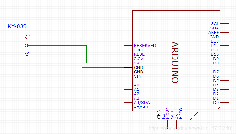
效果图
代码介绍
#define samp_siz 4
#define rise_threshold 5
// Pulse Monitor Test Script
int sensorPin = 0;
void setup() {
   Serial.begin(9600);
}
void loop ()
{
   float reads[samp_siz], sum;
   long int now, ptr;
   float last, reader, start;
   float first, second, third, before, print_value;
   bool rising;
   int rise_count;
   int n;
   long int last_beat;
   for (int i = 0; i < samp_siz; i++)
     reads[i] = 0;
   sum = 0;
   ptr = 0;
   while(1)
   {
     // calculate an average of the sensor
     // during a 20 ms period (this will eliminate
     // the 50 Hz noise caused by electric light
     n = 0;
     start = millis();
     reader = 0.;
     do
     {
       reader += analogRead (sensorPin);
       n++;
       now = millis();
     }
     while (now < start + 20);
     reader /= n;  // we got an average
     // Add the newest measurement to an array
     // and subtract the oldest measurement from the array
     // to maintain a sum of last measurements
     sum -= reads[ptr];
     sum += reader;
     reads[ptr] = reader;
     last = sum / samp_siz;
     // now last holds the average of the values in the array
     // check for a rising curve (= a heart beat)
     if (last > before)
     {
       rise_count++;
       if (!rising && rise_count > rise_threshold)
       {
         // Ok, we have detected a rising curve, which implies a heartbeat.
         // Record the time since last beat, keep track of the two previous
         // times (first, second, third) to get a weighed average.
         // The rising flag prevents us from detecting the same rise
         // more than once.
         rising = true;
         first = millis() - last_beat;
         last_beat = millis();
         // Calculate the weighed average of heartbeat rate
         // according to the three last beats
         print_value = 60000. / (0.4 * first + 0.3 * second + 0.3 * third);
         Serial.print(print_value);
         Serial.print('\n');
         third = second;
         second = first;
       }
     }
     else
     {
       // Ok, the curve is falling
       rising = false;
       rise_count = 0;
     }
     before = last;
     ptr++;
     ptr %= samp_siz;
   }
}
常用传感器讲解四–水位传感器(water sensor)
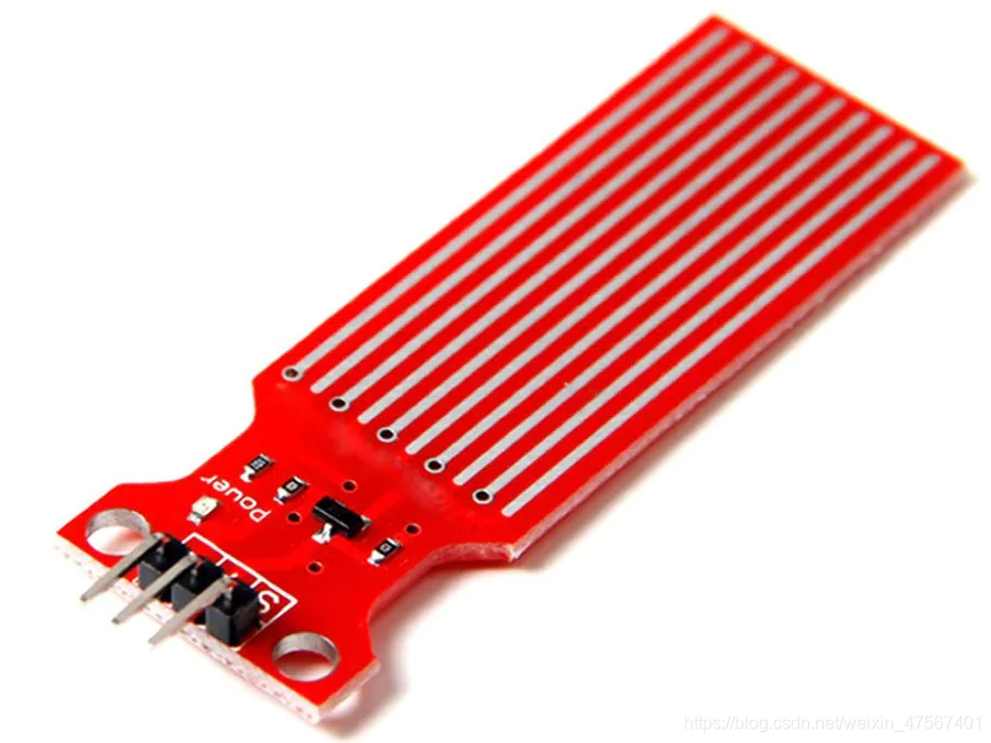
具体讲解
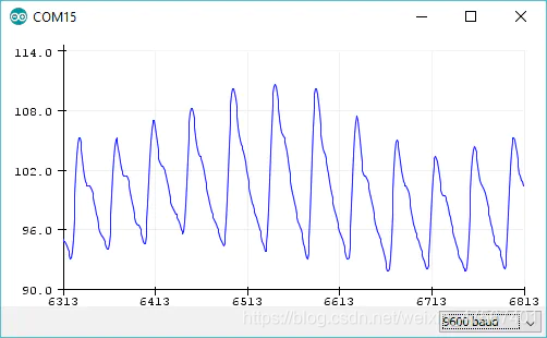
该传感器通过使用一系列五个连接到系统接地的裸露走线来工作。在每两个接地迹线之间交错插入一个感测迹线,五个接地迹线和总共五个感测迹线。感测走线连接到一个1兆欧的上拉电阻。感测迹线被拉高,直到一滴水或水平面使感测迹线接地。理论上,此传感器将输出0-1024之间的模拟信号,但随着PCB上的走线长度的增加,我发现可用范围在480至〜710之间。传感器未设计为完全浸入水中,请谨慎安装,以便仅PCB上裸露的走线会与水接触。传感器的输出电压为0-4.2 V,因此如果仅需要低/高指示,则可以将其用作数字输入。
模拟量输出值对应于与传感器底部的以下距离(近似值):
480 = 0毫米
530 = 5毫米
615 = 10毫米
660 = 15毫米
680 = 20毫米
690 = 25毫米
700 = 30毫米
705 = 35毫米
710 = 40毫米
传感器分辨率随着水位的增加而降低。
==安装
1.将草图上传到您的Arduino。
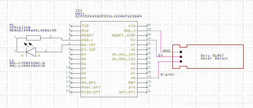
2.使用该项目随附的原理图组装电路。
** LED:LED电阻器必须安装在电路接地和LED之间。如果您的LED的一个分支比另一个分支更长,则需要将更长的分支连接到电源电压(Arduino的D2)。
*注意:我使用的传感器线长约为2.5英尺,LED的线长为2英尺。这使我可以将Arduino放在远离水的地方,并将LED布线到树枝的末端以提高可视性。
3.按照下面的校准说明进行操作(也包括在草图中):
*********校准/设置 *********
a)将Arduino连接到IDE并打开串行监视器。
b)将深度传感器插入水中,直到您认为是触发满指示器所需的最小深度。请注意串行监视器中指示的值,以用作全电平。
*任何大于等于=的值都会触发相应的全闪烁代码。
c)重复步骤2,确定您将分配给LOW值的值。
*高于此值但低于FULL值的任何值都将触发相应的INTERMEDIATE闪烁代码。
*低于此值的任何值都会触发相应的LOW闪烁代码。
d)将步骤2和3中确定的值插入到草图中的const int FULL和LOW值中。
e)使用更新后的值上传草图,现在传感器已校准。
4.将Arduino放在某种类型的外壳上,以防止水,运动部件或短路损坏。
5.将系统安装到您的应用程序中。
编号零件名称零件编号数量
R1 1k 1/4 W电阻TE Connectivity CFR16J1K0(或类似产品)1
L1 LED CREE C503B-RAN-CZ0C0AA2(或类似产品)1
S1传感器Solu SL067 1
IC1 Arduino纳米A000005 1
PS电源您可以选择5 Vdc(> = 300mA)1
电路连接
实现代码
const int full = 575;
const int low = 490;
int depthSensor = 0; //Set depthSensor input pin to Analog 0.
int lastValue = 0;
char printBuffer[128];

/* The following line sets the LED pin to the corresponding digital pin of the
Arduino.  You can set these to any digital pin as needed
*/

const int whiteLED = 2;

void setup()
{
Serial.begin(9600); // Begin serial communication to obtain sensor values during calibration.
pinMode(whiteLED, OUTPUT); // Set LED pin to OUTPUT mode.
}

void loop()
{
int value = analogRead(depthSensor); // Read the sensor values.
if(((lastValue >= value) && ((lastValue - value) > 10)) || (lastValue = 10)) /* If the delta
  between last and current value is > 10, display the current value. */
{
  // Displays depth sensor value to serial port.
  sprintf(printBuffer, "ADC%d level is %d\n", depthSensor, value);
  Serial.print(printBuffer);
  Serial.println();
  //Serial.println(value);
  //Serial.println();
  // Set last value to current value for next loop.
  lastValue - value;
}
if(value >= full)
{
  // FULL
  for(int x = 0; x < 3; x++){
  digitalWrite(whiteLED, HIGH);
  delay(800);
  digitalWrite(whiteLED, LOW);
  delay(800);
  }
}
else if((value < full) && (value >= low))
{
  // INTERMEDIATE
  for(int x = 0; x < 2; x++){
  digitalWrite(whiteLED, HIGH);
  delay(1000);
  }
}
else
{
  //LOW
  for(int x = 0; x < 4; x++){
  digitalWrite(whiteLED, HIGH);
  delay(100);
  digitalWrite(whiteLED, LOW);
  delay(100);
  }
}
delay(3000);  // Read current sensor value every three seconds.
}


 591
591

 被折叠的 条评论
为什么被折叠?
被折叠的 条评论
为什么被折叠?
 到【灌水乐园】发言


